2006 INFINITI M35 fuel type
[x] Cancel search: fuel typePage 3308 of 5621
![INFINITI M35 2006 Factory Service Manual ENGINE ASSEMBLY
EM-245
[VK45DE]
C
D
E
F
G
H
I
J
K
L
MA
EM
Revision: 2006 January2006 M35/M45
Always use the support point specified for lifting.
Use either 2-pole lift type or separate type li INFINITI M35 2006 Factory Service Manual ENGINE ASSEMBLY
EM-245
[VK45DE]
C
D
E
F
G
H
I
J
K
L
MA
EM
Revision: 2006 January2006 M35/M45
Always use the support point specified for lifting.
Use either 2-pole lift type or separate type li](/manual-img/42/57023/w960_57023-3307.png)
ENGINE ASSEMBLY
EM-245
[VK45DE]
C
D
E
F
G
H
I
J
K
L
MA
EM
Revision: 2006 January2006 M35/M45
Always use the support point specified for lifting.
Use either 2-pole lift type or separate type lift as best you can. If board-on type is used for
unavoidable reasons, support at the rear axle jacking point with transmission jack or similar tool
before starting work, in preparation for the backward shift of center of gravity.
For supporting points for lifting and jacking point at rear axle, refer to GI-42, "Garage Jack and
Safety Stand and 2-Pole Lift" .
REMOVAL
Outline
At first, remove engine, transmission assembly with front suspension member from vehicle downward. Then
separate engine from transmission.
Preparation
1. Release fuel pressure. Refer to EC-809, "FUEL PRESSURE RELEASE" .
2. Drain engine coolant from radiator. Refer to CO-40, "
Changing Engine Coolant" .
CAUTION:
Perform this step when engine is cold.
Do not spill engine coolant on drive belts.
3. Disconnect both battery cables. Refer to SC-4, "
BATTERY" .
4. Remove crankshaft position sensor (POS) from transmission.
CAUTION:
Handle carefully to avoid dropping and shocks.
Do not disassemble.
Do not allow metal powder to adhere to magnetic part at sensor tip.
Do not place sensors in a location where they are exposed to magnetism.
5. Remove the following parts:
Front and rear engine undercover (power tool)
Air duct (inlet), air duct and air cleaner case assembly; Refer to EM-177, "AIR CLEANER AND AIR
DUCT" .
Front road wheels and tires (power tool)
Engine Room LH
1. Disconnect heater hoses, and install plugs to avoid leakage of engine coolant.
2. Disconnect wire bonding from exhaust manifold cover to vehicle.
3. Disconnect vacuum hose between vehicle and engine and set it aside.
4. Discharge refrigerant from A/C circuit. Refer to ATC-151, "
REFRIGERANT LINES" .
5. Remove A/C piping from A/C compressor, and temporarily fasten it on vehicle with a rope. Refer to AT C -
151, "REFRIGERANT LINES" .
Engine Room RH
1. Disconnect fuel feed hose and EVAP hose. Refer to EM-193, "FUEL INJECTOR AND FUEL TUBE" .
CAUTION:
Fit plugs onto disconnected hose to prevent fuel leak.
2. Disconnect ground cable (between vehicle and right bank cylinder head).
3. Disconnect vacuum hose between vehicle and engine and set it aside.
4. Disconnect reservoir tank of power steering oil pump from engine, and move it aside for easier work.
CAUTION:
When temporarily securing, keep reservoir tank upright to avoid a fluid leak.
Ve h i c le i n s i d e
Follow procedure below to disconnect engine room harness connectors at passenger room side, and tempo-
rarily secure them on engine.
1. Remove passenger-side kicking plate, dash side finisher, and glove box. Refer to EI-37, "
BODY SIDE
TRIM" and IP-10, "INSTRUMENT PANEL ASSEMBLY" .
2. Disconnect engine room harness connectors at unit sides TCM, ECM and other.
Page 3433 of 5621
![INFINITI M35 2006 Factory Service Manual FSU-6
[2WD]
FRONT SUSPENSION ASSEMBLY
Revision: 2006 January2006 M35/M45
FRONT SUSPENSION ASSEMBLYPFP:54010
On-Vehicle Inspection and ServiceNES000IA
Make sure the mounting conditions (looseness, INFINITI M35 2006 Factory Service Manual FSU-6
[2WD]
FRONT SUSPENSION ASSEMBLY
Revision: 2006 January2006 M35/M45
FRONT SUSPENSION ASSEMBLYPFP:54010
On-Vehicle Inspection and ServiceNES000IA
Make sure the mounting conditions (looseness,](/manual-img/42/57023/w960_57023-3432.png)
FSU-6
[2WD]
FRONT SUSPENSION ASSEMBLY
Revision: 2006 January2006 M35/M45
FRONT SUSPENSION ASSEMBLYPFP:54010
On-Vehicle Inspection and ServiceNES000IA
Make sure the mounting conditions (looseness, back lash) of each component and component conditions
(wear, damage) are normal.
INSPECTION OF LOWER BALL JOINT END PLAY
1. Set front wheels in a straight-ahead position. Do not depress brake pedal.
2. Place an iron bar or similar tool between transverse link and steering knuckle.
3. Measure axial end play by prying it up and down.
CAUTION:
Be careful not to damage ball joint boot. Do not damage the installation position by applying
excessive force.
SHOCK ABSORBER INSPECTION
Check for oil leakage, damage and breakage of installation positions.
Wheel Alignment InspectionNES000IB
DESCRIPTION
Measure wheel alignment under unladen conditions.
NOTE:
“Unladen conditions” means that fuel, engine coolant, and lubricant are full. Spare tire, jack, hand tools and
mats are in designated positions.
PRELIMINARY CHECK
Check the following:
1. Tires for improper air pressure and wear.
2. Road wheels for runout. Refer to WT-6, "
ROAD WHEEL" .
3. Wheel bearing axial end play. Refer to FAX-5, "
WHEEL BEARING INSPECTION" .
4. Transverse link ball joint axial end play. Refer to FSU-14, "
INSPECTION AFTER REMOVAL" .
5. Shock absorber operation.
6. Each mounting part of axle and suspension for looseness and deformation.
7. Each of suspension member, shock absorber, upper link and transverse link for cracks, deformation and
other damage.
8. Vehicle height (posture).
GENERAL INFORMATION AND RECOMMENDATIONS
A four-wheel thrust alignment should be performed.
–This type of alignment is recommended for any NISSAN/INFINITI vehicle.
–The four-wheel “thrust” process helps ensure that the vehicle is properly aligned and the steering wheel is
centered.
–The alignment rack itself should be capable of accepting any NISSAN/INFINITI vehicle.
–The rack should be checked to ensure that it is level.
Make sure the machine is properly calibrated.
–Your alignment equipment should be regularly calibrated in order to give correct information.
–Check with the manufacturer of your specific equipment for their recommended Service/Calibration
Schedule.Axial end play : 0 mm (0 in)
Page 3450 of 5621
![INFINITI M35 2006 Factory Service Manual FRONT SUSPENSION ASSEMBLY
FSU-23
[AWD]
C
D
F
G
H
I
J
K
L
MA
B
FSU
Revision: 2006 January2006 M35/M45
FRONT SUSPENSION ASSEMBLYPFP:54010
On-Vehicle Inspection and ServiceNES000IQ
Make sure the mount INFINITI M35 2006 Factory Service Manual FRONT SUSPENSION ASSEMBLY
FSU-23
[AWD]
C
D
F
G
H
I
J
K
L
MA
B
FSU
Revision: 2006 January2006 M35/M45
FRONT SUSPENSION ASSEMBLYPFP:54010
On-Vehicle Inspection and ServiceNES000IQ
Make sure the mount](/manual-img/42/57023/w960_57023-3449.png)
FRONT SUSPENSION ASSEMBLY
FSU-23
[AWD]
C
D
F
G
H
I
J
K
L
MA
B
FSU
Revision: 2006 January2006 M35/M45
FRONT SUSPENSION ASSEMBLYPFP:54010
On-Vehicle Inspection and ServiceNES000IQ
Make sure the mounting conditions (looseness, back lash) of each component and component conditions
(wear, damage) are normal.
INSPECTION OF LOWER BALL JOINT END PLAY
1. Set front wheels in a straight-ahead position. Do not depress brake pedal.
2. Place an iron bar or similar tool between transverse link and steering knuckle.
3. Measure axial end play by prying it up and down.
CAUTION:
Be careful not to damage ball joint boot. Do not damage the installation position by applying
excessive force.
SHOCK ABSORBER INSPECTION
Check for oil leakage, damage and breakage of installation positions.
Wheel Alignment InspectionNES000IR
DESCRIPTION
Measure wheel alignment under unladen conditions.
NOTE:
“Unladen conditions” means that fuel, engine coolant, and lubricant are full. Spare tire, jack, hand tools and
mats are in designated positions.
PRELIMINARY CHECK
Check the following:
1. Tires for improper air pressure and wear.
2. Road wheels for runout. Refer to WT-6, "
ROAD WHEEL" .
3. Wheel bearing axial end play. Refer to FAX-5, "
WHEEL BEARING INSPECTION" .
4. Transverse link ball joint axial end play. Refer to FSU-31, "
INSPECTION AFTER REMOVAL" .
5. Shock absorber operation.
6. Each mounting part of axle and suspension for looseness and deformation.
7. Each of suspension member, shock absorber, upper link and transverse link for cracks, deformation and
other damage.
8. Vehicle height (posture).
GENERAL INFORMATION AND RECOMMENDATIONS
A four-wheel thrust alignment should be performed.
–This type of alignment is recommended for any NISSAN/INFINITI vehicle.
–The four-wheel “thrust” process helps ensure that the vehicle is properly aligned and the steering wheel is
centered.
–The alignment rack itself should be capable of accepting any NISSAN/INFINITI vehicle.
–The rack should be checked to ensure that it is level.
Make sure the machine is properly calibrated.
–Your alignment equipment should be regularly calibrated in order to give correct information.
–Check with the manufacturer of your specific equipment for their recommended Service/Calibration
Schedule.Axial end play : 0 mm (0 in)
Page 4465 of 5621

LT-38
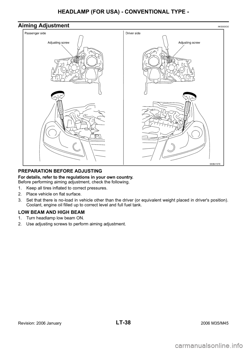
HEADLAMP (FOR USA) - CONVENTIONAL TYPE -
Revision: 2006 January2006 M35/M45
Aiming AdjustmentNKS003OG
PREPARATION BEFORE ADJUSTING
For details, refer to the regulations in your own country.
Before performing aiming adjustment, check the following.
1. Keep all tires inflated to correct pressures.
2. Place vehicle on flat surface.
3. Set that there is no-load in vehicle other than the driver (or equivalent weight placed in driver's position).
Coolant, engine oil filled up to correct level and full fuel tank.
LOW BEAM AND HIGH BEAM
1. Turn headlamp low beam ON.
2. Use adjusting screws to perform aiming adjustment.
SKIB4157E
Page 4501 of 5621

LT-74
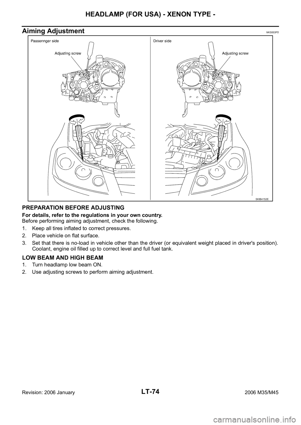
HEADLAMP (FOR USA) - XENON TYPE -
Revision: 2006 January2006 M35/M45
Aiming AdjustmentNKS003P5
PREPARATION BEFORE ADJUSTING
For details, refer to the regulations in your own country.
Before performing aiming adjustment, check the following.
1. Keep all tires inflated to correct pressures.
2. Place vehicle on flat surface.
3. Set that there is no-load in vehicle other than the driver (or equivalent weight placed in driver's position).
Coolant, engine oil filled up to correct level and full fuel tank.
LOW BEAM AND HIGH BEAM
1. Turn headlamp low beam ON.
2. Use adjusting screws to perform aiming adjustment.
SKIB4152E
Page 4778 of 5621

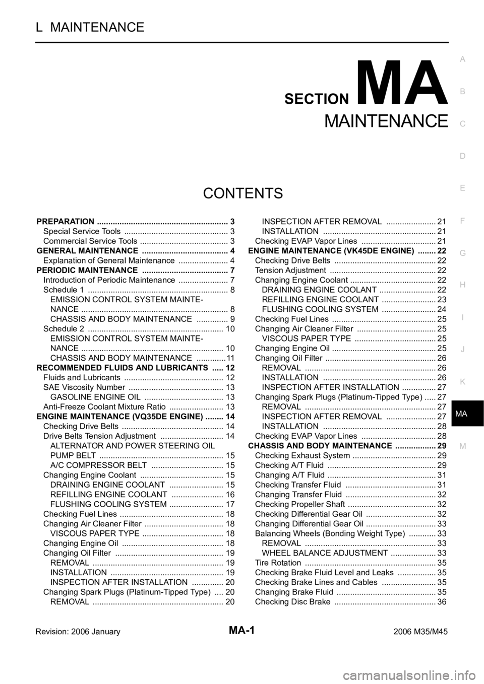
MA-1
MAINTENANCE
L MAINTENANCE
CONTENTS
C
D
E
F
G
H
I
J
K
M
SECTION MA
A
B
MA
Revision: 2006 January2006 M35/M45
MAINTENANCE
PREPARATION ........................................................... 3
Special Service Tools ............................................... 3
Commercial Service Tools ........................................ 3
GENERAL MAINTENANCE ....................................... 4
Explanation of General Maintenance ....................... 4
PERIODIC MAINTENANCE ....................................... 7
Introduction of Periodic Maintenance ....................... 7
Schedule 1 ............................................................... 8
EMISSION CONTROL SYSTEM MAINTE-
NANCE .................................................................. 8
CHASSIS AND BODY MAINTENANCE ............... 9
Schedule 2 ............................................................. 10
EMISSION CONTROL SYSTEM MAINTE-
NANCE ................................................................ 10
CHASSIS AND BODY MAINTENANCE .............. 11
RECOMMENDED FLUIDS AND LUBRICANTS ...... 12
Fluids and Lubricants ............................................. 12
SAE Viscosity Number ........................................... 13
GASOLINE ENGINE OIL .................................... 13
Anti-Freeze Coolant Mixture Ratio ......................... 13
ENGINE MAINTENANCE (VQ35DE ENGINE) ......... 14
Checking Drive Belts .............................................. 14
Drive Belts Tension Adjustment ............................. 14
ALTERNATOR AND POWER STEERING OIL
PUMP BELT ........................................................ 15
A/C COMPRESSOR BELT ................................. 15
Changing Engine Coolant ...................................... 15
DRAINING ENGINE COOLANT ......................... 15
REFILLING ENGINE COOLANT ........................ 16
FLUSHING COOLING SYSTEM ......................... 17
Checking Fuel Lines ............................................ ... 18
Changing Air Cleaner Filter .................................... 18
VISCOUS PAPER TYPE ..................................... 18
Changing Engine Oil .............................................. 18
Changing Oil Filter ................................................. 19
REMOVAL ........................................................
... 19
INSTALLATION ................................................... 19
INSPECTION AFTER INSTALLATION ............... 20
Changing Spark Plugs (Platinum-Tipped Type) ..... 20
REMOVAL ........................................................
... 20INSPECTION AFTER REMOVAL ....................... 21
INSTALLATION ................................................... 21
Checking EVAP Vapor Lines .................................. 21
ENGINE MAINTENANCE (VK45DE ENGINE) ......... 22
Checking Drive Belts .............................................. 22
Tension Adjustment .............................................
... 22
Changing Engine Coolant ....................................... 22
DRAINING ENGINE COOLANT .......................... 22
REFILLING ENGINE COOLANT ......................... 23
FLUSHING COOLING SYSTEM ......................... 24
Checking Fuel Lines ............................................ ... 25
Changing Air Cleaner Filter .................................... 25
VISCOUS PAPER TYPE ..................................... 25
Changing Engine Oil ............................................
... 25
Changing Oil Filter .................................................. 26
REMOVAL ........................................................
... 26
INSTALLATION ................................................... 26
INSPECTION AFTER INSTALLATION ................ 27
Changing Spark Plugs (Platinum-Tipped Type) ...... 27
REMOVAL ........................................................
... 27
INSPECTION AFTER REMOVAL ....................... 27
INSTALLATION ................................................... 28
Checking EVAP Vapor Lines .................................. 28
CHASSIS AND BODY MAINTENANCE ................... 29
Checking Exhaust System ...................................... 29
Checking A/T Fluid ................................................. 29
Changing A/T Fluid ................................................. 31
Checking Transfer Fluid ......................................... 31
Changing Transfer Fluid ......................................... 32
Checking Propeller Shaft ........................................ 32
Checking Differential Gear Oil ................................ 32
Changing Differential Gear Oil ................................ 33
Balancing Wheels (Bonding Weight Type) ............. 33
REMOVAL ........................................................
... 33
WHEEL BALANCE ADJUSTMENT ..................... 33
Tire Rotation ........................................................... 35
Checking Brake Fluid Level and Leaks .................. 35
Checking Brake Lines and Cables ......................... 35
Changing Brake Fluid ............................................. 35
Checking Disc Brake .............................................. 36
Page 4785 of 5621
![INFINITI M35 2006 Factory Service Manual MA-8
PERIODIC MAINTENANCE
Revision: 2006 January2006 M35/M45
Schedule 1NLS0007C
EMISSION CONTROL SYSTEM MAINTENANCE
Abbreviations: R = Replace. I = Inspect. Correct or replace if necessary. [ ]: At th INFINITI M35 2006 Factory Service Manual MA-8
PERIODIC MAINTENANCE
Revision: 2006 January2006 M35/M45
Schedule 1NLS0007C
EMISSION CONTROL SYSTEM MAINTENANCE
Abbreviations: R = Replace. I = Inspect. Correct or replace if necessary. [ ]: At th](/manual-img/42/57023/w960_57023-4784.png)
MA-8
PERIODIC MAINTENANCE
Revision: 2006 January2006 M35/M45
Schedule 1NLS0007C
EMISSION CONTROL SYSTEM MAINTENANCE
Abbreviations: R = Replace. I = Inspect. Correct or replace if necessary. [ ]: At the mileage intervals only
MAINTENANCE OPERATIONMAINTENANCE INTERVAL
Reference
Section -
Page or -
Content Title Perform at number of miles,
kilometers or months, which-
ever comes first.Miles x 1,000
(km x 1,000)
Months3.75
(6)
37.50
(12)
611 . 2 5
(18)
915
(24)
1218.75
(30)
1522.5
(36)
1826.25
(42)
2130
(48)
24
Drive belts NOTE (1)MA-14
,
MA-22
Air cleaner filter NOTE (2) [R]MA-18,
MA-25
EVAP vapor linesI*MA-21,
MA-28
Fuel linesI*MA-18,
MA-25
Fuel filter NOTE (3)—
Engine coolant NOTE (4)MA-15
,
MA-22
Engine oil R R RRRRR RMA-18,
MA-25
Engine oil filter [Use part No.
15208 31U00 (for VK45DE),
15208 65F00 (for VQ35DE)
or equivalent.]R R RRRRR RMA-19
,
MA-26
Spark plugs (PLATINUM-
TIPPED type)Replace every 105,000 miles (169,000 km).MA-20,
MA-27
Intake & exhaust valve clear-
ance*NOTE (5)EM-93, "Valve Clear-
ance", EM-
222, "Va l v e
Clearance"
MAINTENANCE OPERATIONMAINTENANCE INTERVAL
Reference
Section -
Page or -
Content Title Perform at number of miles,
kilometers or months, which-
ever comes first.Miles x 1,000
(km x 1,000)
Months33.75
(54)
2737.5
(60)
3041.25
(66)
3345
(72)
3648.75
(78)
3952.5
(84)
4256.25
(90)
4560
(96)
48
Drive belts NOTE (1) I*MA-14
,
MA-22
Air cleaner filter NOTE (2) [R]MA-18,
MA-25
EVAP vapor linesI*MA-21,
MA-28
Fuel linesI*MA-18,
MA-25
Fuel filter NOTE (3)—
Engine coolant NOTE (4) R*MA-15
,
MA-22
Engine oil R R R R R R R RMA-18,
MA-25
Engine oil filter [Use part No.
15208 31U00 (for VK45DE),
15208 65F00 (for VQ35DE)
or equivalent.]R R RRRRRRMA-19
,
MA-26
Page 4787 of 5621

MA-10
PERIODIC MAINTENANCE
Revision: 2006 January2006 M35/M45
NOTE:
(1) If towing a trailer, using a camper or a car-top carrier, or driving on rough or muddy roads, change (not just inspect) fluid (A/T, trans-
fer)/oil at every 30,000 miles (48,000 km) or 24 months. Using automatic transmission fluid other than Genuine NISSAN Matic J
ATF will cause deterioration in driveability and automatic transmission durability, and may damage the automatic transmis-
sion, which is not covered by the INFINITI new vehicle limited warranty.
(2) Refer to “Tire rotation” under the “GENERAL MAINTENANCE” heading earlier in this section.
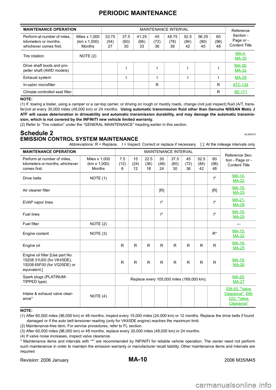
Schedule 2NLS0007D
EMISSION CONTROL SYSTEM MAINTENANCE
Abbreviations: R = Replace. I = Inspect. Correct or replace if necessary. [ ]: At the mileage intervals only
NOTE:
(1) After 60,000 miles (96,000 km) or 48 months, inspect every 15,000 miles (24,000 km) or 12 months. Replace the drive belts if found
damaged or if the auto belt tensioner reading (only for VK45DE engine) reaches the maximum limit.
(2) Maintenance-free item. For service procedures, refer to FL section.
(3) After 60,000 miles (96,000 km) or 48 months, replace every 30,000 miles (48,000 km) or 24 months.
(4) If valve noise increases, inspect valve clearance.
* Maintenance items and intervals with “*” are recommended by INFINITI for reliable vehicle operation. The owner need not perform
such maintenance in order to maintain the emission warranty or manufacturer recall liability. Other maintenance items and intervals are
required Tire rotation NOTE (2)MA-4
,
MA-35
Drive shaft boots and pro-
peller shaft (AWD models)I IIIMA-38,
MA-32
Exhaust system I I I IMA-29
In-cabin microfilter R RATC-134
Climate controlled seat filterRSE-171
MAINTENANCE OPERATIONMAINTENANCE INTERVAL
Reference
Section -
Page or -
Content Title Perform at number of miles,
kilometers or months,
whichever comes first.Miles x 1,000
(km x 1,000)
Months33.75
(54)
2737.5
(60)
3041.25
(66)
3345
(72)
3648.75
(78)
3952.5
(84)
4256.25
(90)
4560
(96)
48
MAINTENANCE OPERATIONMAINTENANCE INTERVAL
Reference Sec-
tion - Page or -
Content Title Perform at number of miles,
kilometers or months, whichever
comes first.Miles x 1,000
(km x 1,000)
Months7.5
(12)
615
(24)
1222.5
(36)
1830
(48)
2437.5
(60)
3045
(72)
3652.5
(84)
4260
(96)
48
Drive belts NOTE (1) I*MA-14
,
MA-22
Air cleaner filter [R] [R]MA-18,
MA-25
EVAP vapor lines I* I*MA-21,
MA-28
Fuel lines I* I*MA-18,
MA-25
Fuel filter NOTE (2)—
Engine coolant NOTE (3) R*MA-15
,
MA-22
Engine oil RRRRRRRRMA-18,
MA-25
Engine oil filter [Use part No.
15208 31U00 (for VK45DE),
15208 65F00 (for VQ35DE) or
equivalent.]RRRR R RRRMA-19
,
MA-26
Spark plugs (PLATINUM-
TIPPED type)Replace every 105,000 miles (169,000 km).MA-20,
MA-27
Intake & exhaust valve clear-
ance*NOTE (4)EM-93, "
Va l v e
Clearance", EM-
222, "Va l v e
Clearance"