2006 INFINITI M35 automatic transmission
[x] Cancel search: automatic transmissionPage 3511 of 5621
GI-48
RECOMMENDED CHEMICAL PRODUCTS AND SEALANTS
Revision: 2006 January2006 M35/M45
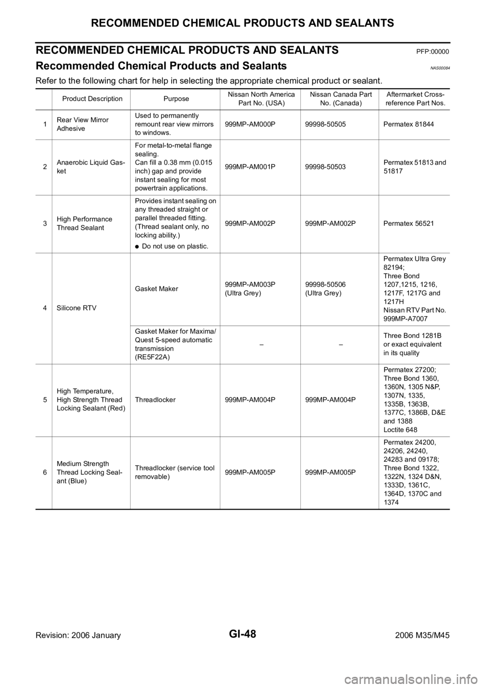
RECOMMENDED CHEMICAL PRODUCTS AND SEALANTSPFP:00000
Recommended Chemical Products and SealantsNAS00084
Refer to the following chart for help in selecting the appropriate chemical product or sealant.
Product Description PurposeNissan North America
Part No. (USA)Nissan Canada Part
No. (Canada)Aftermarket Cross-
reference Part Nos.
1Rear View Mirror
AdhesiveUsed to permanently
remount rear view mirrors
to windows.999MP-AM000P 99998-50505 Permatex 81844
2Anaerobic Liquid Gas-
ketFor metal-to-metal flange
sealing.
Can fill a 0.38 mm (0.015
inch) gap and provide
instant sealing for most
powertrain applications.999MP-AM001P 99998-50503Permatex 51813 and
51817
3High Performance
Thread SealantProvides instant sealing on
any threaded straight or
parallel threaded fitting.
(Thread sealant only, no
locking ability.)
Do not use on plastic.999MP-AM002P 999MP-AM002P Permatex 56521
4 Silicone RTVGasket Maker999MP-AM003P
(Ultra Grey)99998-50506
(Ultra Grey)Permatex Ultra Grey
82194;
Three Bond
1207,1215, 1216,
1217F, 1217G and
1217H
Nissan RTV Part No.
999MP-A7007
Gasket Maker for Maxima/
Quest 5-speed automatic
transmission
(RE5F22A)––Three Bond 1281B
or exact equivalent
in its quality
5High Temperature,
High Strength Thread
Locking Sealant (Red)Threadlocker 999MP-AM004P 999MP-AM004PPermatex 27200;
Three Bond 1360,
1360N, 1305 N&P,
1307N, 1335,
1335B, 1363B,
1377C, 1386B, D&E
and 1388
Loctite 648
6Medium Strength
Thread Locking Seal-
ant (Blue)Threadlocker (service tool
removable)999MP-AM005P 999MP-AM005PPermatex 24200,
24206, 24240,
24283 and 09178;
Three Bond 1322,
1322N, 1324 D&N,
1333D, 1361C,
1364D, 1370C and
1374
Page 3514 of 5621
IDENTIFICATION INFORMATION
GI-51
C
D
E
F
G
H
I
J
K
L
MB
GI
Revision: 2006 January2006 M35/M45
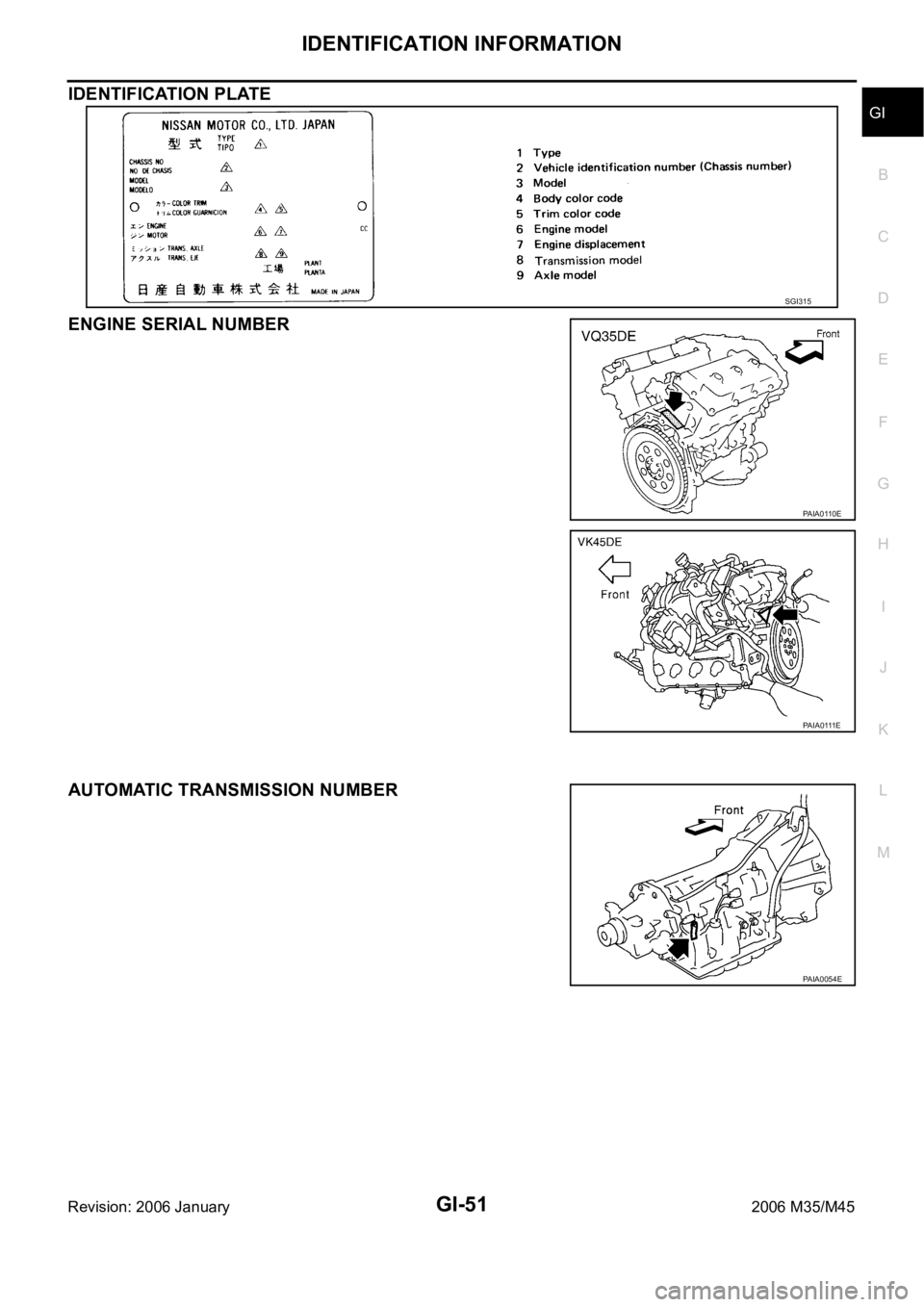
IDENTIFICATION PLATE
ENGINE SERIAL NUMBER
AUTOMATIC TRANSMISSION NUMBER
SGI315
PAIA0110E
PA IA 0 111 E
PAIA0054E
Page 3616 of 5621
![INFINITI M35 2006 Factory Service Manual REVERSE INTERLOCK DOOR MIRROR SYSTEM
GW-97
C
D
E
F
G
H
J
K
L
MA
B
GW
Revision: 2006 January2006 M35/M45
through 10A fuse [No.21, located in the fuse block (J/B)]
to automatic drive positioner control INFINITI M35 2006 Factory Service Manual REVERSE INTERLOCK DOOR MIRROR SYSTEM
GW-97
C
D
E
F
G
H
J
K
L
MA
B
GW
Revision: 2006 January2006 M35/M45
through 10A fuse [No.21, located in the fuse block (J/B)]
to automatic drive positioner control](/manual-img/42/57023/w960_57023-3615.png)
REVERSE INTERLOCK DOOR MIRROR SYSTEM
GW-97
C
D
E
F
G
H
J
K
L
MA
B
GW
Revision: 2006 January2006 M35/M45
through 10A fuse [No.21, located in the fuse block (J/B)]
to automatic drive positioner control unit terminal 34 and
to driver seat control unit terminal 40.
Ground is supplied
to automatic drive positioner control unit terminals 40 and 48.
through body grounds M16 and M70.
to driver seat control unit terminals 32 and 48.
through body grounds B5, B40 and B131.
to door mirror remote control switch terminal 13
through body grounds M16 and M70.
REVERSE INTERLOCK DOOR MIRROR SYSTEM OPERATION
When the ignition switch is in ON position, A/T control device into R position. Then TCM (in A/T assembly)
detects it and sends the A/T shift position signal to the driver seat control unit via DATA LINE (CAN H,
CAN L).
When selecting either left and right changeover switch, the automatic drive position control unit judges
which door mirror is selected according to the voltage of terminals 2 and 18. And then, it sends the signal
to driver seat control unit via communication signal.
When the driver seat control unit receives the A/T shift position signal and changeover switch signal, it
sends the operation signal to the automatic drive positioner control unit using the communication signal so
that the each mirror sensor voltage stays in a specified value.
Door mirror (RH) selected
Supply the power from terminals 14, 15 and 30 to door mirror (RH) terminals 5, 6 and 7 so that the voltage
of terminals 5 and 21 stays in a specified value. Then, adjust the mirror angle.
Door mirror (LH) selected
Supply the power from terminals 16, 31 and 32 to door mirror (LH) terminals 5, 6 and 7 do that the voltage
of terminals 6 and 22 is the specified value. Then, adjust the mirror angle.
CAN Communication System DescriptionNIS00232
CAN (Controller Area Network) is a serial communication line for real time application. It is an on-vehicle mul-
tiplex communication line with high data communication speed and excellent error detection ability. Many elec-
tronic control units are equipped onto a vehicle, and each control unit shares information and links with other
control units during operation (not independent). In CAN communication, control units are connected with 2
communication lines (CAN H line, CAN L line) allowing a high rate of information transmission with less wiring.
Each control unit transmits/receives data but selectively reads required data only.
CAN Communication UnitNIS00233
Refer to LAN-34, "CAN Communication Unit" .
Page 3643 of 5621
IDX-2
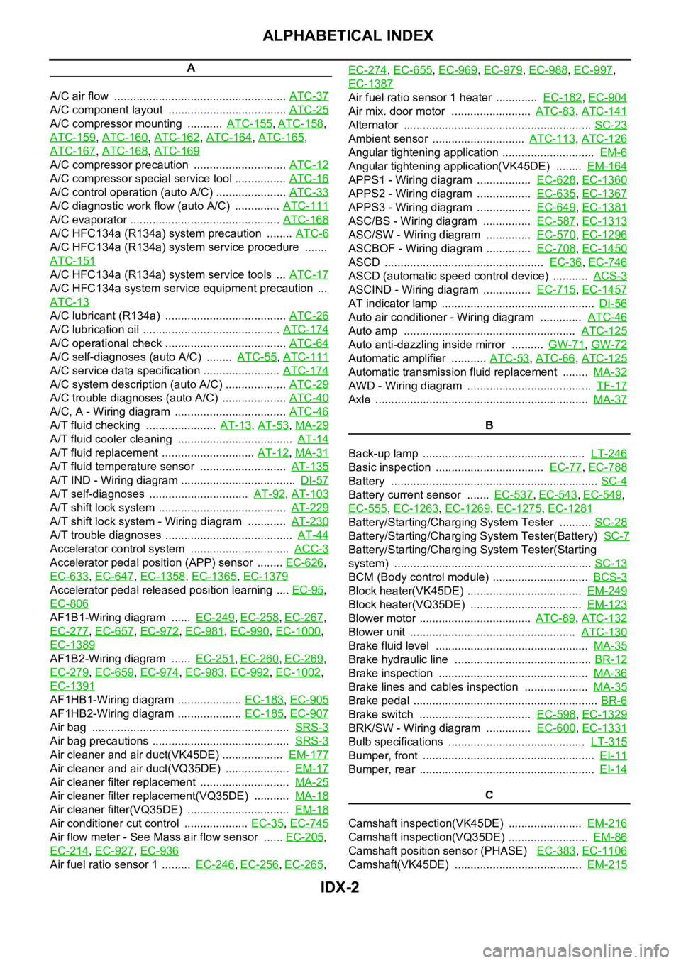
ALPHABETICAL INDEX
A
A/C air flow ...................................................... ATC-37
A/C component layout ..................................... ATC-25
A/C compressor mounting ........... ATC-155, ATC-158,
ATC-159
, ATC-160, ATC-162, ATC-164, ATC-165,
ATC-167
, ATC-168, ATC-169
A/C compressor precaution ............................. ATC-12
A/C compressor special service tool ................ ATC-16
A/C control operation (auto A/C) ...................... ATC-33
A/C diagnostic work flow (auto A/C) .............. ATC-111
A/C evaporator ............................................... ATC-168
A/C HFC134a (R134a) system precaution ........ ATC-6
A/C HFC134a (R134a) system service procedure .......
ATC-151
A/C HFC134a (R134a) system service tools ... ATC-17
A/C HFC134a system service equipment precaution ...
ATC-13
A/C lubricant (R134a) ...................................... ATC-26
A/C lubrication oil ........................................... ATC-174
A/C operational check ...................................... ATC-64
A/C self-diagnoses (auto A/C) ........ ATC-55, ATC-111
A/C service data specification ........................ ATC-174
A/C system description (auto A/C) ................... ATC-29
A/C trouble diagnoses (auto A/C) .................... ATC-40
A/C, A - Wiring diagram ................................... ATC-46
A/T fluid checking ...................... AT-13, AT-53, MA-29
A/T fluid cooler cleaning .................................... AT-14
A/T fluid replacement ............................. AT-12, MA-31
A/T fluid temperature sensor ........................... AT-135
A/T IND - Wiring diagram .................................... DI-57
A/T self-diagnoses ............................... AT-92, AT-103
A/T shift lock system ........................................ AT-229
A/T shift lock system - Wiring diagram ............ AT-230
A/T trouble diagnoses ........................................ AT-44
Accelerator control system ............................... ACC-3
Accelerator pedal position (APP) sensor ........ EC-626,
EC-633
, EC-647, EC-1358, EC-1365, EC-1379
Accelerator pedal released position learning .... EC-95,
EC-806
AF1B1-Wiring diagram ...... EC-249, EC-258, EC-267,
EC-277
, EC-657, EC-972, EC-981, EC-990, EC-1000,
EC-1389
AF1B2-Wiring diagram ...... EC-251, EC-260, EC-269,
EC-279
, EC-659, EC-974, EC-983, EC-992, EC-1002,
EC-1391
AF1HB1-Wiring diagram .................... EC-183, EC-905
AF1HB2-Wiring diagram .................... EC-185, EC-907
Air bag .............................................................. SRS-3
Air bag precautions ........................................... SRS-3
Air cleaner and air duct(VK45DE) ................... EM-177
Air cleaner and air duct(VQ35DE) .................... EM-17
Air cleaner filter replacement ............................ MA-25
Air cleaner filter replacement(VQ35DE) ........... MA-18
Air cleaner filter(VQ35DE) ................................ EM-18
Air conditioner cut control .................... EC-35, EC-745
Air flow meter - See Mass air flow sensor ...... EC-205,
EC-214
, EC-927, EC-936
Air fuel ratio sensor 1 ......... EC-246, EC-256, EC-265, EC-274
, EC-655, EC-969, EC-979, EC-988, EC-997,
EC-1387
Air fuel ratio sensor 1 heater ............. EC-182, EC-904
Air mix. door motor ......................... ATC-83, ATC-141
Alternator ........................................................... SC-23
Ambient sensor ............................. ATC-113, ATC-126
Angular tightening application ............................. EM-6
Angular tightening application(VK45DE) ........ EM-164
APPS1 - Wiring diagram ................. EC-628, EC-1360
APPS2 - Wiring diagram ................. EC-635, EC-1367
APPS3 - Wiring diagram ................. EC-649, EC-1381
ASC/BS - Wiring diagram ............... EC-587, EC-1313
ASC/SW - Wiring diagram .............. EC-570, EC-1296
ASCBOF - Wiring diagram .............. EC-708, EC-1450
ASCD .................................................. EC-36, EC-746
ASCD (automatic speed control device) ........... ACS-3
ASCIND - Wiring diagram ............... EC-715, EC-1457
AT indicator lamp ................................................ DI-56
Auto air conditioner - Wiring diagram ............. ATC-46
Auto amp ...................................................... ATC-125
Auto anti-dazzling inside mirror .......... GW-71, GW-72
Automatic amplifier ........... ATC-53, ATC-66, ATC-125
Automatic transmission fluid replacement ........ MA-32
AWD - Wiring diagram ....................................... TF-17
Axle ................................................................... MA-37
B
Back-up lamp ................................................... LT-246
Basic inspection .................................. EC-77, EC-788
Battery ................................................................. SC-4
Battery current sensor ....... EC-537, EC-543, EC-549,
EC-555
, EC-1263, EC-1269, EC-1275, EC-1281
Battery/Starting/Charging System Tester .......... SC-28
Battery/Starting/Charging System Tester(Battery) SC-7
Battery/Starting/Charging System Tester(Starting
system) .............................................................. SC-13
BCM (Body control module) .............................. BCS-3
Block heater(VK45DE) .................................... EM-249
Block heater(VQ35DE) ................................... EM-123
Blower motor ................................... ATC-89, ATC-132
Blower unit .................................................... ATC-130
Brake fluid level ................................................ MA-35
Brake hydraulic line ........................................... BR-12
Brake inspection ............................................... MA-36
Brake lines and cables inspection .................... MA-35
Brake pedal .......................................................... BR-6
Brake switch ................................... EC-598, EC-1329
BRK/SW - Wiring diagram .............. EC-600, EC-1331
Bulb specifications ........................................... LT-315
Bumper, front ...................................................... EI-11
Bumper, rear ....................................................... EI-14
C
Camshaft inspection(VK45DE) ....................... EM-216
Camshaft inspection(VQ35DE) ......................... EM-86
Camshaft position sensor (PHASE) EC-383, EC-1106
Camshaft(VK45DE) ........................................ EM-215
Page 4724 of 5621
ILLUMINATION
LT-297
C
D
E
F
G
H
I
J
L
MA
B
LT
Revision: 2006 January2006 M35/M45
to door mirror remote control switch (illumination) terminal 15
to AFS switch (illumination) terminal 6 (with AFS)
to rear sunshade front switch (illumination) terminal 6 (with rear control switch)
to A/T illumination terminal 2
to snow mode switch (illumination) terminal 6 (ADW models)
to rear control cancel switch (illumination) terminal 5 (with rear control switch)
to clock terminal 4
to multifunction switch terminal 4
to audio unit terminal 8
to DVD player terminal 17 (With DVD player)
to climate controlled seat switch driver side (illumination) terminal 8 (with climate controlled seat) and
to climate controlled seat switch passenger side (illumination) terminal 8 (with climate controlled seat)
through illumination control switch terminal 2
to illumination control switch terminal 3
through grounds M16 and M70,
to cigarette lighter socket (illumination) terminal 1
to map lamp (illumination) terminal 4
to power window main switch illumination terminal 2 and
to glove box lamp terminal 2
through grounds M16 and M70,
to ashtray illumination (rear LH) terminal 2
to ashtray illumination (rear RH) terminal 2
to automatic return cancel switch (illumination) terminal 2 (With rear control switch)
to rear power seat switch LH (illumination) terminal 3 (With rear control switch)
to rear heated seat switch LH (illumination) terminal 8 (With rear control switch)
through grounds B5, B40 and B131,
through rear sunshade cancel relay terminal 7(With rear control switch)
to rear sunshade rear switch (illumination) terminal 7 (With rear control switch)
through grounds B5, B40, B131 and B559.
to rear control switch terminal 4
to rear power seat switch RH (illumination) terminal 3 (With rear control switch)
to rear heated seat switch RH (illumination) terminal 8 (With rear control switch)
through grounds B5, B40, B131 and B559.
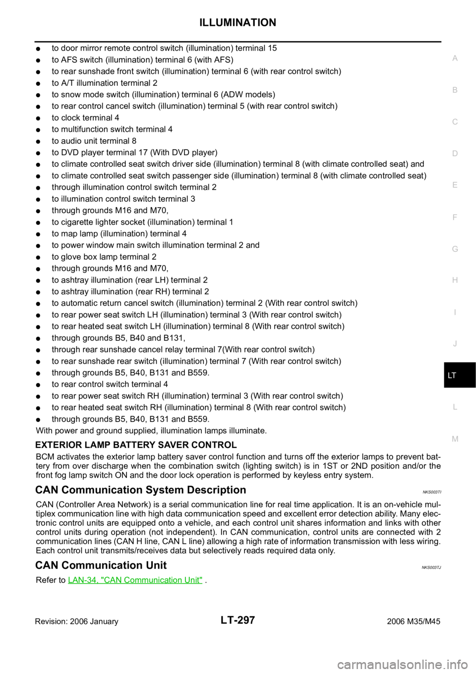
With power and ground supplied, illumination lamps illuminate.
EXTERIOR LAMP BATTERY SAVER CONTROL
BCM activates the exterior lamp battery saver control function and turns off the exterior lamps to prevent bat-
tery from over discharge when the combination switch (lighting switch) is in 1ST or 2ND position and/or the
front fog lamp switch ON and the door lock operation is performed by keyless entry system.
CAN Communication System DescriptionNKS003TI
CAN (Controller Area Network) is a serial communication line for real time application. It is an on-vehicle mul-
tiplex communication line with high data communication speed and excellent error detection ability. Many elec-
tronic control units are equipped onto a vehicle, and each control unit shares information and links with other
control units during operation (not independent). In CAN communication, control units are connected with 2
communication lines (CAN H line, CAN L line) allowing a high rate of information transmission with less wiring.
Each control unit transmits/receives data but selectively reads required data only.
CAN Communication UnitNKS003TJ
Refer to LAN-34, "CAN Communication Unit" .
Page 4786 of 5621
PERIODIC MAINTENANCE
MA-9
C
D
E
F
G
H
I
J
K
MA
B
MA
Revision: 2006 January2006 M35/M45
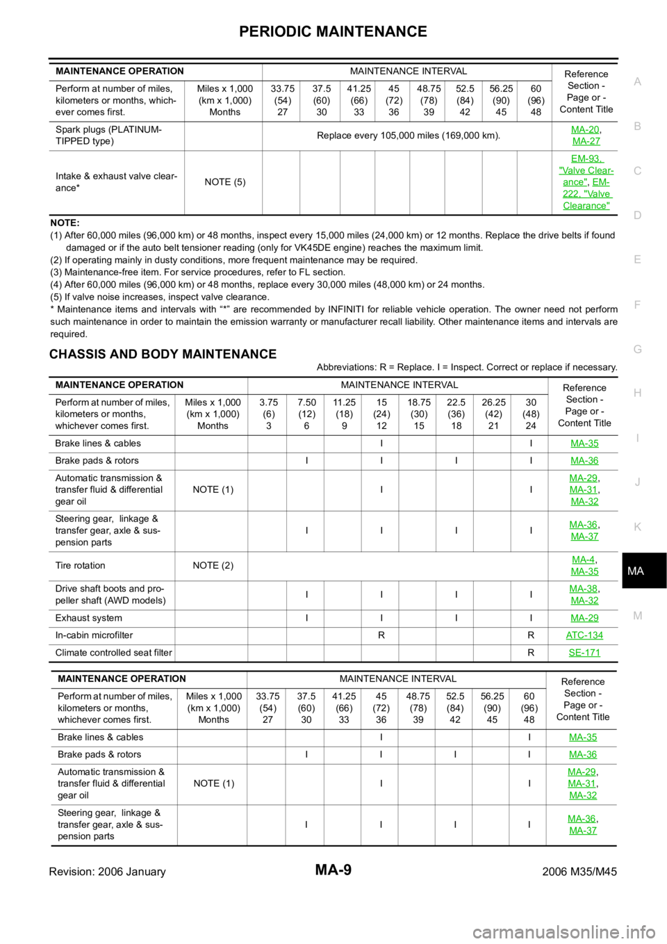
NOTE:
(1) After 60,000 miles (96,000 km) or 48 months, inspect every 15,000 miles (24,000 km) or 12 months. Replace the drive belts if found
damaged or if the auto belt tensioner reading (only for VK45DE engine) reaches the maximum limit.
(2) If operating mainly in dusty conditions, more frequent maintenance may be required.
(3) Maintenance-free item. For service procedures, refer to FL section.
(4) After 60,000 miles (96,000 km) or 48 months, replace every 30,000 miles (48,000 km) or 24 months.
(5) If valve noise increases, inspect valve clearance.
* Maintenance items and intervals with “*” are recommended by INFINITI for reliable vehicle operation. The owner need not perform
such maintenance in order to maintain the emission warranty or manufacturer recall liability. Other maintenance items and intervals are
required.
CHASSIS AND BODY MAINTENANCE
Abbreviations: R = Replace. I = Inspect. Correct or replace if necessary. Spark plugs (PLATINUM-
TIPPED type)Replace every 105,000 miles (169,000 km).MA-20
,
MA-27
Intake & exhaust valve clear-
ance*NOTE (5)EM-93, "Valve Clear-
ance", EM-
222, "Va l v e
Clearance"
MAINTENANCE OPERATIONMAINTENANCE INTERVAL
Reference
Section -
Page or -
Content Title Perform at number of miles,
kilometers or months, which-
ever comes first.Miles x 1,000
(km x 1,000)
Months33.75
(54)
2737.5
(60)
3041.25
(66)
3345
(72)
3648.75
(78)
3952.5
(84)
4256.25
(90)
4560
(96)
48
MAINTENANCE OPERATIONMAINTENANCE INTERVAL
Reference
Section -
Page or -
Content Title Perform at number of miles,
kilometers or months,
whichever comes first.Miles x 1,000
(km x 1,000)
Months3.75
(6)
37.50
(12)
611 . 2 5
(18)
915
(24)
1218.75
(30)
1522.5
(36)
1826.25
(42)
2130
(48)
24
Brake lines & cables I IMA-35
Brake pads & rotors I I I IMA-36
Automatic transmission &
transfer fluid & differential
gear oilNOTE (1) I IMA-29,
MA-31
,
MA-32
Steering gear, linkage &
transfer gear, axle & sus-
pension partsIIIIMA-36,
MA-37
Tire rotation NOTE (2)MA-4,
MA-35
Drive shaft boots and pro-
peller shaft (AWD models) IIIIMA-38,
MA-32
Exhaust system I I I IMA-29
In-cabin microfilter R RAT C - 1 3 4
Climate controlled seat filterRSE-171
MAINTENANCE OPERATIONMAINTENANCE INTERVAL
Reference
Section -
Page or -
Content Title Perform at number of miles,
kilometers or months,
whichever comes first.Miles x 1,000
(km x 1,000)
Months33.75
(54)
2737.5
(60)
3041.25
(66)
3345
(72)
3648.75
(78)
3952.5
(84)
4256.25
(90)
4560
(96)
48
Brake lines & cables I IMA-35
Brake pads & rotors I I I IMA-36
Automatic transmission &
transfer fluid & differential
gear oilNOTE (1) I IMA-29,
MA-31
,
MA-32
Steering gear, linkage &
transfer gear, axle & sus-
pension partsI IIIMA-36,
MA-37
Page 4787 of 5621
MA-10
PERIODIC MAINTENANCE
Revision: 2006 January2006 M35/M45
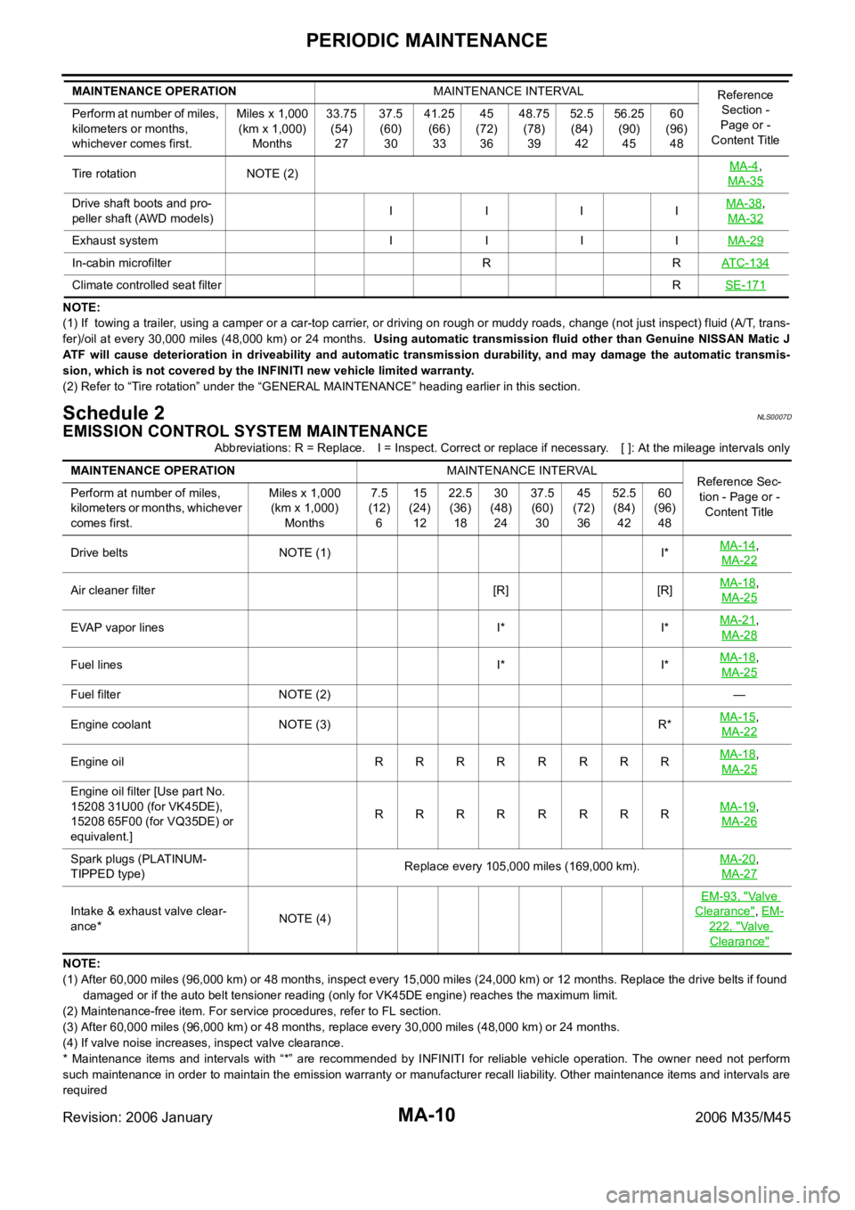
NOTE:
(1) If towing a trailer, using a camper or a car-top carrier, or driving on rough or muddy roads, change (not just inspect) fluid (A/T, trans-
fer)/oil at every 30,000 miles (48,000 km) or 24 months. Using automatic transmission fluid other than Genuine NISSAN Matic J
ATF will cause deterioration in driveability and automatic transmission durability, and may damage the automatic transmis-
sion, which is not covered by the INFINITI new vehicle limited warranty.
(2) Refer to “Tire rotation” under the “GENERAL MAINTENANCE” heading earlier in this section.
Schedule 2NLS0007D
EMISSION CONTROL SYSTEM MAINTENANCE
Abbreviations: R = Replace. I = Inspect. Correct or replace if necessary. [ ]: At the mileage intervals only
NOTE:
(1) After 60,000 miles (96,000 km) or 48 months, inspect every 15,000 miles (24,000 km) or 12 months. Replace the drive belts if found
damaged or if the auto belt tensioner reading (only for VK45DE engine) reaches the maximum limit.
(2) Maintenance-free item. For service procedures, refer to FL section.
(3) After 60,000 miles (96,000 km) or 48 months, replace every 30,000 miles (48,000 km) or 24 months.
(4) If valve noise increases, inspect valve clearance.
* Maintenance items and intervals with “*” are recommended by INFINITI for reliable vehicle operation. The owner need not perform
such maintenance in order to maintain the emission warranty or manufacturer recall liability. Other maintenance items and intervals are
required Tire rotation NOTE (2)MA-4
,
MA-35
Drive shaft boots and pro-
peller shaft (AWD models)I IIIMA-38,
MA-32
Exhaust system I I I IMA-29
In-cabin microfilter R RATC-134
Climate controlled seat filterRSE-171
MAINTENANCE OPERATIONMAINTENANCE INTERVAL
Reference
Section -
Page or -
Content Title Perform at number of miles,
kilometers or months,
whichever comes first.Miles x 1,000
(km x 1,000)
Months33.75
(54)
2737.5
(60)
3041.25
(66)
3345
(72)
3648.75
(78)
3952.5
(84)
4256.25
(90)
4560
(96)
48
MAINTENANCE OPERATIONMAINTENANCE INTERVAL
Reference Sec-
tion - Page or -
Content Title Perform at number of miles,
kilometers or months, whichever
comes first.Miles x 1,000
(km x 1,000)
Months7.5
(12)
615
(24)
1222.5
(36)
1830
(48)
2437.5
(60)
3045
(72)
3652.5
(84)
4260
(96)
48
Drive belts NOTE (1) I*MA-14
,
MA-22
Air cleaner filter [R] [R]MA-18,
MA-25
EVAP vapor lines I* I*MA-21,
MA-28
Fuel lines I* I*MA-18,
MA-25
Fuel filter NOTE (2)—
Engine coolant NOTE (3) R*MA-15
,
MA-22
Engine oil RRRRRRRRMA-18,
MA-25
Engine oil filter [Use part No.
15208 31U00 (for VK45DE),
15208 65F00 (for VQ35DE) or
equivalent.]RRRR R RRRMA-19
,
MA-26
Spark plugs (PLATINUM-
TIPPED type)Replace every 105,000 miles (169,000 km).MA-20,
MA-27
Intake & exhaust valve clear-
ance*NOTE (4)EM-93, "
Va l v e
Clearance", EM-
222, "Va l v e
Clearance"
Page 4788 of 5621
PERIODIC MAINTENANCE
MA-11
C
D
E
F
G
H
I
J
K
MA
B
MA
Revision: 2006 January2006 M35/M45
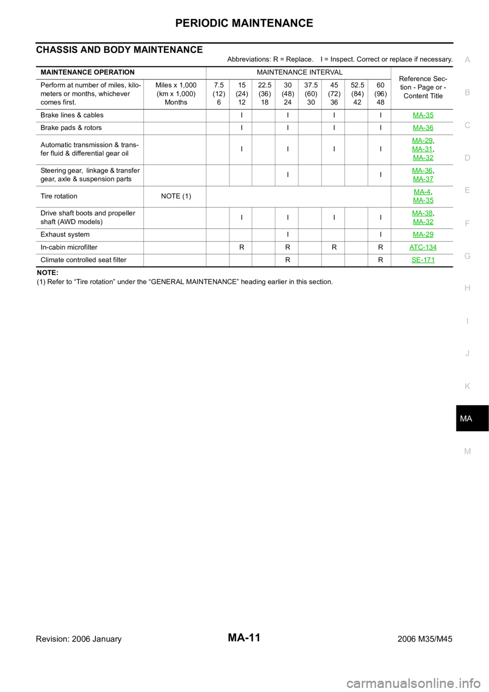
CHASSIS AND BODY MAINTENANCE
Abbreviations: R = Replace. I = Inspect. Correct or replace if necessary.
NOTE:
(1) Refer to “Tire rotation” under the “GENERAL MAINTENANCE” heading earlier in this section. MAINTENANCE OPERATIONMAINTENANCE INTERVAL
Reference Sec-
tion - Page or -
Content Title Perform at number of miles, kilo-
meters or months, whichever
comes first.Miles x 1,000
(km x 1,000)
Months7.5
(12)
615
(24)
1222.5
(36)
1830
(48)
2437.5
(60)
3045
(72)
3652.5
(84)
4260
(96)
48
Brake lines & cables I I I IMA-35
Brake pads & rotors I I I IMA-36
Automatic transmission & trans-
fer fluid & differential gear oilIIIIMA-29,
MA-31
,
MA-32
Steering gear, linkage & transfer
gear, axle & suspension partsIIMA-36,
MA-37
Tire rotation NOTE (1)MA-4,
MA-35
Drive shaft boots and propeller
shaft (AWD models) IIIIMA-38,
MA-32
Exhaust system I IMA-29
In-cabin microfilter R R R RATC-134
Climate controlled seat filter R RSE-171