Page 4987 of 5621
PS-34
POWER STEERING OIL PUMP
Revision: 2006 January2006 M35/M45
Disassembly and Assembly (Models with VQ35DE)NGS000DH
COMPONENTS
INSPECTION BEFORE DISASSEMBLY
Disassemble oil pump only when the following malfunctions occur.
If oil leakage is found on oil pump.
Oil pump pulley is damaged or deformed.
Performance of oil pump is low.
1. Pulley 2. Oil seal 3. Bracket
4. Body assembly 5. Suction pipe 6. O-ring
7. Flow control valve B assembly 8. Flow control valve spring 9. Flow control valve A
10. Dowel pin 11. Front side plate 12. Vane
13. Rotor 14. Rotor snap ring 15. Cam ring
16. Rear side plate 17. O-ring 18. Teflon ring
19. O-ring 20. Rear cover 21. Cartridge
Refer to GI-11, "
Components" , and the followings for the symbols in the figure.
: Apply power steering fluid.
: Apply multi-purpose grease.
SGIA1188E
Page 4988 of 5621

POWER STEERING OIL PUMP
PS-35
C
D
E
F
H
I
J
K
L
MA
B
PS
Revision: 2006 January2006 M35/M45
DISASSEMBLY
NOTE:
Secure oil pump in a vise if necessary.
CAUTION:
Use copper plates when securing in a vise.
1. Remove rear cover mounting bolts, and then remove rear cover from body assembly.
2. Remove O-ring from body assembly.
3. Remove rear side plate from cartridge, and then remove Teflon ring and O-ring from rear side plate.
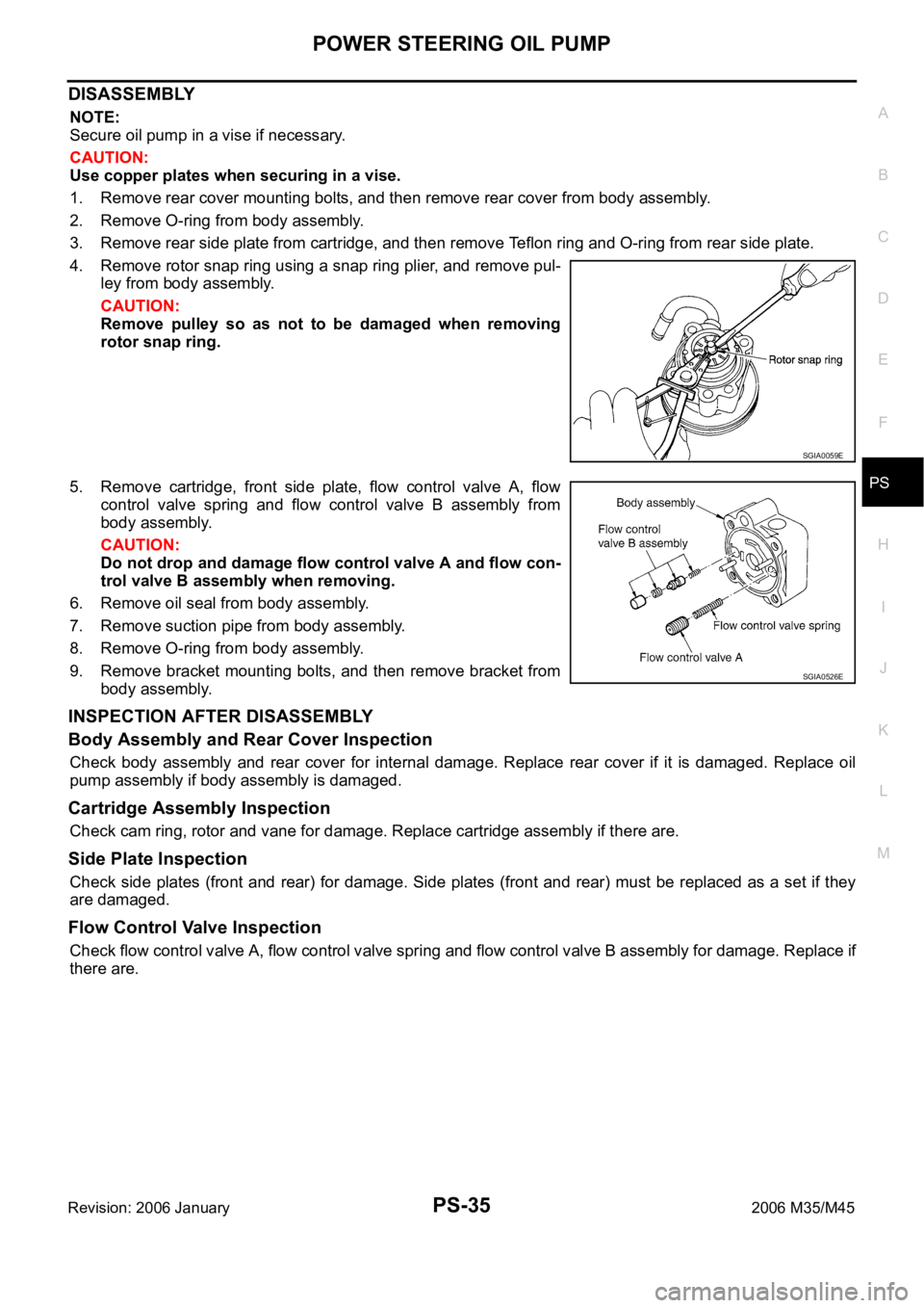
4. Remove rotor snap ring using a snap ring plier, and remove pul-
ley from body assembly.
CAUTION:
Remove pulley so as not to be damaged when removing
rotor snap ring.
5. Remove cartridge, front side plate, flow control valve A, flow
control valve spring and flow control valve B assembly from
body assembly.
CAUTION:
Do not drop and damage flow control valve A and flow con-
trol valve B assembly when removing.
6. Remove oil seal from body assembly.
7. Remove suction pipe from body assembly.
8. Remove O-ring from body assembly.
9. Remove bracket mounting bolts, and then remove bracket from
body assembly.
INSPECTION AFTER DISASSEMBLY
Body Assembly and Rear Cover Inspection
Check body assembly and rear cover for internal damage. Replace rear cover if it is damaged. Replace oil
pump assembly if body assembly is damaged.
Cartridge Assembly Inspection
Check cam ring, rotor and vane for damage. Replace cartridge assembly if there are.
Side Plate Inspection
Check side plates (front and rear) for damage. Side plates (front and rear) must be replaced as a set if they
are damaged.
Flow Control Valve Inspection
Check flow control valve A, flow control valve spring and flow control valve B assembly for damage. Replace if
there are.
SGIA0059E
SGIA0526E
Page 4989 of 5621

PS-36
POWER STEERING OIL PUMP
Revision: 2006 January2006 M35/M45
ASSEMBLY
NOTE:
Secure oil pump in a vise if necessary.
CAUTION:
Use copper plates when securing in a vise.
1. Apply multi purpose grease to oil seal lips. Apply power steering
fluid to around oil seal, and then install oil seal to body assembly
using the drift [SST].
2. Install bracket to body assembly, and then tighten mounting
bolts to the specified torque.
3. If dowel pin has been removed, insert it into body assembly by
hand. If cannot be inserted by hand, lightly tap with a hammer.
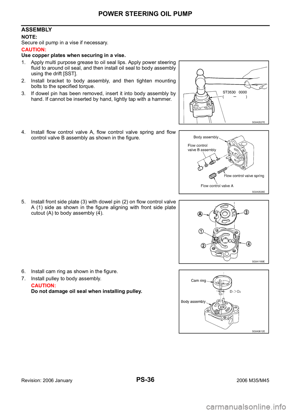
4. Install flow control valve A, flow control valve spring and flow
control valve B assembly as shown in the figure.
5. Install front side plate (3) with dowel pin (2) on flow control valve
A (1) side as shown in the figure aligning with front side plate
cutout (A) to body assembly (4).
6. Install cam ring as shown in the figure.
7. Install pulley to body assembly.
CAUTION:
Do not damage oil seal when installing pulley.
SGIA0527E
SGIA0526E
SGIA1189E
SGIA0612E
Page 4990 of 5621

POWER STEERING OIL PUMP
PS-37
C
D
E
F
H
I
J
K
L
MA
B
PS
Revision: 2006 January2006 M35/M45
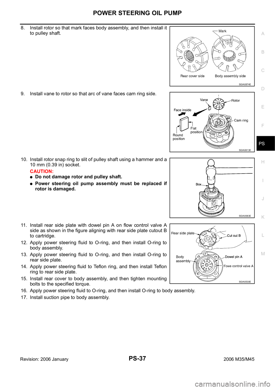
8. Install rotor so that mark faces body assembly, and then install it
to pulley shaft.
9. Install vane to rotor so that arc of vane faces cam ring side.
10. Install rotor snap ring to slit of pulley shaft using a hammer and a
10 mm (0.39 in) socket.
CAUTION:
Do not damage rotor and pulley shaft.
Power steering oil pump assembly must be replaced if
rotor is damaged.
11. Install rear side plate with dowel pin A on flow control valve A
side as shown in the figure aligning with rear side plate cutout B
to cartridge.
12. Apply power steering fluid to O-ring, and then install O-ring to
body assembly.
13. Apply power steering fluid to O-ring, and then install O-ring to
rear side plate.
14. Apply power steering fluid to Teflon ring, and then install Te f l o n
ring to rear side plate.
15. Install rear cover to body assembly, and then tighten mounting
bolts to the specified torque.
16. Apply power steering fluid to O-ring, and then install O-ring to body assembly.
17. Install suction pipe to body assembly.
SGIA0874E
SGIA0613E
SGIA0063E
SGIA0530E
Page 4992 of 5621
HYDRAULIC LINE
PS-39
C
D
E
F
H
I
J
K
L
MA
B
PS
Revision: 2006 January2006 M35/M45
1. Reservoir tank 2. Reservoir tank bracket 3. Suction hose
4. High pressure hose 5. Oil pump assembly 6. Steering gear assembly
7. Low pressure piping 8. High pressure piping 9. O-ring
10. Eye-bolt 11. Copper washer 12. Eye-joint (assembled to high-pres-
sure side hose)
13. Pressure sensor 14. Oil pump bracket
Refer to GI-11, "
Components" , and the followings for the symbols in the figure.
: Apply power steering fluid.
Page 4994 of 5621
HYDRAULIC LINE
PS-41
C
D
E
F
H
I
J
K
L
MA
B
PS
Revision: 2006 January2006 M35/M45
Refer to GI-11, "Components" , and the followings for the symbols in the figure.
: Apply power steering fluid.
Page 4996 of 5621
HYDRAULIC LINE
PS-43
C
D
E
F
H
I
J
K
L
MA
B
PS
Revision: 2006 January2006 M35/M45
Removal and InstallationNGS000DL
Insert hose securely until it contacts tube spool.
CAUTION:
Do not apply fluid.
Install eye-bolt with eye-joint (assembled to high-pressure hose)
protrusion facing with pump side cutout, and then tighten it to
the specified torque after tightening by hand.
Refer to GI-11, "Components" , and the followings for the symbols in the figure.
: Apply power steering fluid.
SGIA0514E
SGIA0515E
Page 5089 of 5621

RSU-8
REAR SUSPENSION ASSEMBLY
Revision: 2006 January2006 M35/M45
Refer to GI section for symbol marks in the figure. Refer to GI-9, "HOW TO USE THIS MANUAL" .
Removal and InstallationNES000J9
REMOVAL
1. Remove tire with a power tool.
2. Remove brake caliper with a power tool. Hang it in a place where it will not interfere with work. Refer to
BR-29, "
REAR DISC BRAKE" .
CAUTION:
Do not depressing brake pedal while brake caliper is removed.
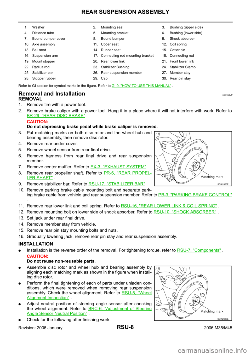
3. Put matching marks on both disc rotor and the wheel hub and
bearing assembly, then remove disc rotor.
4. Remove rear under cover.
5. Remove wheel sensor from rear final drive.
6. Remove harness from rear final drive and rear suspension
member.
7. Remove center muffler. Refer to EX-3, "
EXHAUST SYSTEM" .
8. Remove rear propeller shaft. Refer to PR-6, "
REAR PROPEL-
LER SHAFT" .
9. Remove stabilizer bar. Refer to RSU-17, "
STABILIZER BAR" .
10. Remove parking brake cable mounting bolt and separate park-
ing brake cable from vehicle and rear suspension member. Refer to PB-3, "
PARKING BRAKE CONTROL"
.
11. Remove rear lower link and coil spring. Refer to RSU-16, "
REAR LOWER LINK & COIL SPRING" .
12. Remove mounting bolt on lower side of shock absorber. Refer to RSU-10, "
SHOCK ABSORBER" .
13. Set jack under rear final drive.
14. Remove member stay from vehicle.
15. Remove rear pin stay mounting bolts and nuts.
16. Gradually lowering jack, remove rear pin stay and rear suspension assembly.
INSTALLATION
Installation is the reverse order of the removal. For tightening torque, refer to RSU-7, "Components" .
CAUTION:
Do not reuse non-reusable parts.
Assemble disc rotor and wheel hub and bearing assembly by
aligning each matching mark as shown in the figure when install-
ing disc rotor.
Perform the final tightening of each of parts under unladen con-
ditions, which were removed when removing rear suspension
assembly. Check the wheel alignment. Refer to RSU-5, "
Wheel
Alignment Inspection" .
Adjust neutral position of steering angle sensor after checking
the wheel alignment. Refer to BRC-6, "
Adjustment of Steering
Angle Sensor Neutral Position" .
Check for the following after finishing work.
1. Washer 2. Mounting seal 3. Bushing (upper side)
4. Distance tube 5. Mounting bracket 6. Bushing (lower side)
7. Bound bumper cover 8. Bound bumper 9. Shock absorber
10. Axle assembly 11. Upper seat 12. Coil spring
13. Ball seat 14. Rubber seat 15. Cotter pin
16. Suspension arm 17. Connecting rod mounting bracket 18. Connecting rod
19. Mount stopper 20. Rear lower link 21. Front lower link
22. Radius rod 23. Stabilizer Bushing 24. Stabilizer Clamp
25. Stabilizer bar 26. Rear suspension member 27. Member stay
28. Stopper rubber 29. Cap 30. Rear pin stay
SDIA2638E
SDIA2638E