2006 INFINITI M35 brake
[x] Cancel search: brakePage 1461 of 5621

DI-28
UNIFIED METER AND A/C AMP
Revision: 2006 January2006 M35/M45
UNIFIED METER AND A/C AMPPFP:27760
System DescriptionNKS003UG
For the unified meter and A/C amp., the signal required for controlling the combination meter are integrated in
the A/C auto amp.
COMBINATION METER CONTROL FUNCTION
Unified meter and A/C amp. inputs necessary information for combination meter from each unit with CAN
communication and so on.
Unified meter and A/C amp. outputs signals with communication line (TX, RX) between unified meter and
A/C amp. and combination meter.
Unified meter and A/C amp. corresponds a CONSULT-II function (self-diagnostic results, CAN diagnostic
support monitor and data monitor).
Input/output Signals
Between unified meter and A/C amp. and combination meter.
Unit Input from combination meter Output to combination meter
Unified meter and A/C amp.
Refuel status signal
Low-fuel warning lamp condition signal
Delivery destination data signal
Combination meter receive error signal
Combination meter specifications signal
Odo date signal
Vehicle speed signal
Turn indicator signal
High beam request signal
Ring illumination request signal
Position light request signal
Front fog lamp request signal
SET indicator lamp signal
CRUISE indicator lamp signal
Engine speed signal
Fuel level sensor signal (resistance value)
Engine coolant temperature signal
CAN communication condition signal of A/T
A/T position indicator signal
Manual mode indicator signal
A/T CHECK warning lamp signal
AWD warning lamp signal
Low tire pressure warning lamp signal
VDC OFF indicator lamp signal
SLIP indicator lamp signal
ABS warning lamp signal
Brake warning lamp signal
Malfunction indicator lamp signal
Oil pressure switch signal
Door switch signal
Buzzer request signal
ICC warning lamp signal
Meter display signal
AFS OFF indicator signal
Page 1466 of 5621

UNIFIED METER AND A/C AMP
DI-33
C
D
E
F
G
H
I
J
L
MA
B
DI
Revision: 2006 January2006 M35/M45
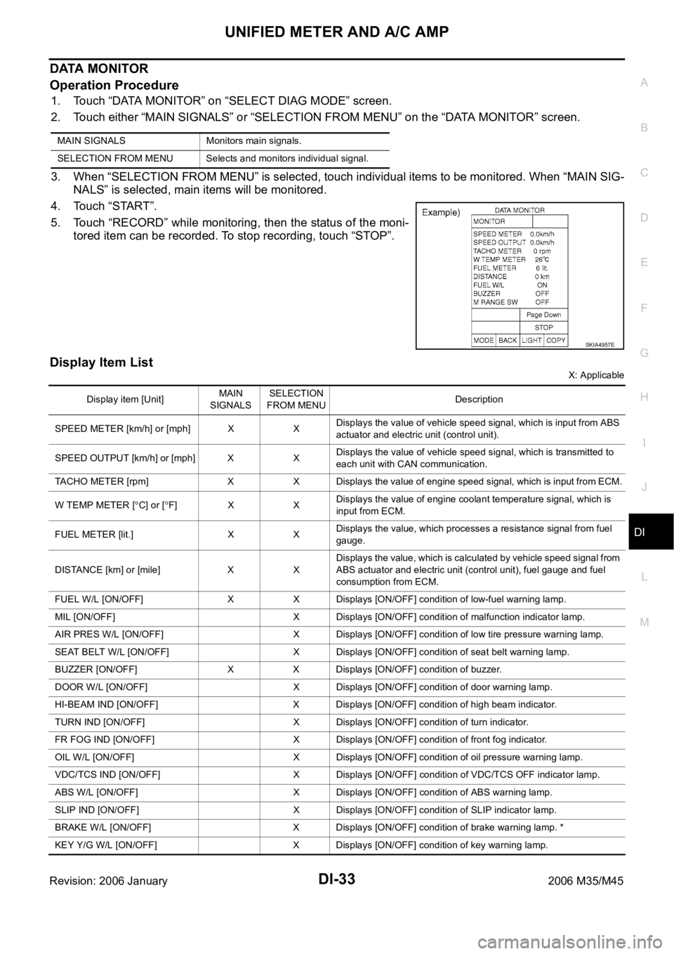
DATA MONITOR
Operation Procedure
1. Touch “DATA MONITOR” on “SELECT DIAG MODE” screen.
2. Touch either “MAIN SIGNALS” or “SELECTION FROM MENU” on the “DATA MONITOR” screen.
3. When “SELECTION FROM MENU” is selected, touch individual items to be monitored. When “MAIN SIG-
NALS” is selected, main items will be monitored.
4. Touch “START”.
5. Touch “RECORD” while monitoring, then the status of the moni-
tored item can be recorded. To stop recording, touch “STOP”.
Display Item List
X: Applicable MAIN SIGNALS Monitors main signals.
SELECTION FROM MENU Selects and monitors individual signal.
SKIA4957E
Display item [Unit]MAIN
SIGNALSSELECTION
FROM MENUDescription
SPEED METER [km/h] or [mph] X XDisplays the value of vehicle speed signal, which is input from ABS
actuator and electric unit (control unit).
SPEED OUTPUT [km/h] or [mph] X XDisplays the value of vehicle speed signal, which is transmitted to
each unit with CAN communication.
TACHO METER [rpm] X X Displays the value of engine speed signal, which is input from ECM.
W TEMP METER [
C] or [F] X XDisplays the value of engine coolant temperature signal, which is
input from ECM.
FUEL METER [lit.] X XDisplays the value, which processes a resistance signal from fuel
gauge.
DISTANCE [km] or [mile] X XDisplays the value, which is calculated by vehicle speed signal from
ABS actuator and electric unit (control unit), fuel gauge and fuel
consumption from ECM.
FUEL W/L [ON/OFF] X X Displays [ON/OFF] condition of low-fuel warning lamp.
MIL [ON/OFF] X Displays [ON/OFF] condition of malfunction indicator lamp.
AIR PRES W/L [ON/OFF] X Displays [ON/OFF] condition of low tire pressure warning lamp.
SEAT BELT W/L [ON/OFF] X Displays [ON/OFF] condition of seat belt warning lamp.
BUZZER [ON/OFF] X X Displays [ON/OFF] condition of buzzer.
DOOR W/L [ON/OFF] X Displays [ON/OFF] condition of door warning lamp.
HI-BEAM IND [ON/OFF] X Displays [ON/OFF] condition of high beam indicator.
TURN IND [ON/OFF] X Displays [ON/OFF] condition of turn indicator.
FR FOG IND [ON/OFF] X Displays [ON/OFF] condition of front fog indicator.
OIL W/L [ON/OFF] X Displays [ON/OFF] condition of oil pressure warning lamp.
VDC/TCS IND [ON/OFF] X Displays [ON/OFF] condition of VDC/TCS OFF indicator lamp.
ABS W/L [ON/OFF] X Displays [ON/OFF] condition of ABS warning lamp.
SLIP IND [ON/OFF] X Displays [ON/OFF] condition of SLIP indicator lamp.
BRAKE W/L [ON/OFF] X Displays [ON/OFF] condition of brake warning lamp. *
KEY Y/G W/L [ON/OFF] X Displays [ON/OFF] condition of key warning lamp.
Page 1467 of 5621

DI-34
UNIFIED METER AND A/C AMP
Revision: 2006 January2006 M35/M45
NOTE:
Monitored item that does not match the vehicle is deleted from the display automatically.
*: Monitor keeps indicating “OFF” when brake warning lamp is on by the parking brake operation or low brake fluid level. PNP P SW [ON/OFF] X X Displays [ON/OFF] condition of inhibitor switch P range.
M RANGE SW [ON/OFF] X X Displays [ON/OFF] condition of manual mode range switch.
NM RANGE SW [ON/OFF] X XDisplays [ON/OFF] condition of except for manual mode range
switch.
AT SFT UP SW [ON/OFF] X X Displays [ON/OFF] condition of A/T shift-up switch.
AT SFT DWN SW [ON/OFF] X X Displays [ON/OFF] condition of A/T shift-down switch.
AT P MODE SW X Displays [ON/OFF] condition of A/T POWER mode switch.
AT S MODE SW X Displays [ON/OFF] condition of A/T SNOW mode switch.
BRAKE SW [ON/OFF] * X Displays [ON/OFF] condition of brake switch (stop lamp switch).
AT-M IND [ON/OFF] X X Displays [ON/OFF] condition of A/T manual mode indicator.
AT-M GEAR [5-1] X X Displays [5-1] condition of A/T manual mode gear position.
P RANGE IND [ON/OFF] X X Displays [ON/OFF] condition of A/T shift P range indicator.
R RANGE IND [ON/OFF] X X Displays [ON/OFF] condition of A/T shift R range indicator.
N RANGE IND [ON/OFF] X X Displays [ON/OFF] condition of A/T shift N range indicator.
D RANGE IND [ON/OFF] X X Displays [ON/OFF] condition of A/T shift D range indicator.
AT IND [ON/OFF] X Displays [ON/OFF] condition of A/T indicator.
CRUISE IND [ON/OFF] X Displays [ON/OFF] condition of CRUISE indicator.
SET IND [ON/OFF] X Displays [ON/OFF] condition of SET indicator.
CRUISE W/L [ON/OFF] X Displays [ON/OFF] condition of CRUISE warning lamp.
4WD W/L [ON/OFF] X Displays [ON/OFF] condition of AWD warning lamp.
AFS OFF IND [ON/OFF] X Displays [ON/OFF] condition of AFS OFF indicator. Display item [Unit]MAIN
SIGNALSSELECTION
FROM MENUDescription
Page 1514 of 5621

LANE DEPARTURE WARNING SYSTEM
DI-81
C
D
E
F
G
H
I
J
L
MA
B
DI
Revision: 2006 January2006 M35/M45
Camera Aiming AdjustmentNKS003VI
OUTLINE
Adjust the camera aiming every time the LDW camera unit is removed or installed.
CAUTION:
Place the vehicle on the level ground when the camera aiming adjustment is operated.
Follow the CONSULT-II when adjusting the camera aiming. (Camera aiming adjustment cannot be
operated without CONSULT-II.)
PREPARATION
Keep all tires inflated to correct pressures. Adjust the tire pressure to the specified pressure value.
There is no-load in vehicle. Check if coolant, engine oil are filled up to correct level and fuel tank is full.
Shift the gear into “P” position and release the parking brake.
Clean the windshield.
NOTE:
Do not place anything reflective on the upper surface of instrument panel.
TARGET SETTING
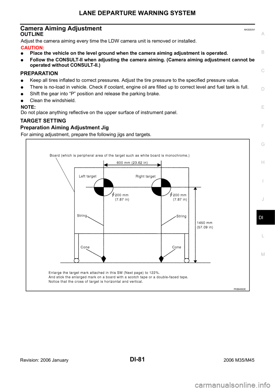
Preparation Aiming Adjustment Jig
For aiming adjustment, prepare the following jigs and targets.
PKIB4693E
Page 1549 of 5621

EC-6Revision: 2006 January2006 M35/M45 On Board Diagnosis Logic ....................................533
DTC Confirmation Procedure ...............................533
Diagnostic Procedure ...........................................534
Removal and Installation ......................................534
DTC P1226 TP SENSOR ........................................535
Component Description ........................................535
On Board Diagnosis Logic ....................................535
DTC Confirmation Procedure ...............................535
Diagnostic Procedure ...........................................536
Removal and Installation ......................................536
DTC P1550 BATTERY CURRENT SENSOR ..........537
Component Description ........................................537
CONSULT-II Reference Value in Data Monitor Mode
.537
On Board Diagnosis Logic ....................................537
DTC Confirmation Procedure ...............................538
Wiring Diagram .....................................................539
Diagnostic Procedure ...........................................540
Component Inspection ..........................................542
D T C P 1 5 5 1 , P 1 5 5 2 B A T T E R Y C U R R E N T S E N S O R .543
Component Description ........................................543
CONSULT-II Reference Value in Data Monitor Mode
.543
On Board Diagnosis Logic ....................................543
DTC Confirmation Procedure ...............................544
Wiring Diagram .....................................................545
Diagnostic Procedure ...........................................546
Component Inspection ..........................................548
DTC P1553 BATTERY CURRENT SENSOR ..........549
Component Description ........................................549
CONSULT-II Reference Value in Data Monitor Mode
.549
On Board Diagnosis Logic ....................................549
DTC Confirmation Procedure ...............................550
Wiring Diagram .....................................................551
Diagnostic Procedure ...........................................552
Component Inspection ..........................................554
DTC P1554 BATTERY CURRENT SENSOR ..........555
Component Description ........................................555
CONSULT-II Reference Value in Data Monitor Mode
.555
On Board Diagnosis Logic ....................................555
Overall Function Check ........................................556
Wiring Diagram .....................................................557
Diagnostic Procedure ...........................................558
Component Inspection ..........................................560
DTC P1564 ICC STEERING SWITCH ....................561
Component Description ........................................561
CONSULT-II Reference Value in Data Monitor Mode
.561
On Board Diagnosis Logic ....................................561
DTC Confirmation Procedure ...............................562
Wiring Diagram ................................................
.....563
Diagnostic Procedure ...........................................564
Component Inspection ..........................................567
DTC P1564 ASCD STEERING SWITCH ................568
Component Description ........................................568
CONSULT-II Reference Value in Data Monitor Mode
.568On Board Diagnosis Logic ....................................568
DTC Confirmation Procedure ................................569
Wiring Diagram .....................................................570
Diagnostic Procedure ............................................571
Component Inspection ..........................................574
DTC P1568 ICC FUNCTION ...................................575
On Board Diagnosis Logic ....................................575
DTC Confirmation Procedure ................................575
Diagnostic Procedure ............................................575
DTC P1572 ICC BRAKE SWITCH ..........................576
Component Description ........................................576
CONSULT-II Reference Value in Data Monitor Mode
.576
On Board Diagnosis Logic ....................................576
DTC Confirmation Procedure ................................577
Wiring Diagram .....................................................578
Diagnostic Procedure ............................................579
Component Inspection ..........................................584
DTC P1572 ASCD BRAKE SWITCH ......................585
Component Description ........................................585
CONSULT-II Reference Value in Data Monitor Mode
.585
On Board Diagnosis Logic ....................................585
DTC Confirmation Procedure ................................586
Wiring Diagram .....................................................587
Diagnostic Procedure ............................................588
Component Inspection ..........................................592
DTC P1574 ICC VEHICLE SPEED SENSOR .........593
Component Description ........................................593
On Board Diagnosis Logic ....................................593
DTC Confirmation Procedure ................................593
Diagnostic Procedure ............................................594
DTC P1574 ASCD VEHICLE SPEED SENSOR .....595
Component Description ........................................595
On Board Diagnosis Logic ....................................595
DTC Confirmation Procedure ................................595
Diagnostic Procedure ............................................596
DTC P1715 INPUT SPEED SENSOR (TURBINE
REVOLUTION SENSOR) ........................................597
Description ............................................................597
CONSULT-II Reference Value in Data Monitor Mode
.597
On Board Diagnosis Logic ....................................597
Diagnostic Procedure ..........................................
..597
DTC P1805 BRAKE SWITCH .................................598
Component Description ........................................598
CONSULT-II Reference Value in Data Monitor Mode
.598
On Board Diagnosis Logic ....................................598
DTC Confirmation Procedure ................................599
Wiring Diagram .....................................................600
Diagnostic Procedure ............................................601
Component Inspection ..........................................606
DTC P2100, P2103 THROTTLE CONTROL MOTOR
RELAY .....................................................................607
Component Description ........................................607
CONSULT-II Reference Value in Data Monitor Mode
.607
On Board Diagnosis Logic ....................................607
Page 1550 of 5621

EC-7
C
D
E
F
G
H
I
J
K
L
M
ECA
Revision: 2006 January2006 M35/M45 DTC Confirmation Procedure ...............................607
Wiring Diagram ....................................................609
Diagnostic Procedure ...........................................610
DTC P2101 ELECTRIC THROTTLE CONTROL
FUNCTION ..............................................................613
Description ...........................................................613
On Board Diagnosis Logic ...................................613
DTC Confirmation Procedure ...............................613
Wiring Diagram ....................................................614
Diagnostic Procedure ...........................................615
Component Inspection .........................................618
Removal and Installation ......................................618
DTC P2118 THROTTLE CONTROL MOTOR ........619
Component Description ........................................619
On Board Diagnosis Logic ...................................619
DTC Confirmation Procedure ...............................619
Wiring Diagram ....................................................620
Diagnostic Procedure ...........................................621
Component Inspection .........................................622
Removal and Installation ......................................623
DTC P2119 ELECTRIC THROTTLE CONTROL
ACTUATOR ............................................................624
Component Description ........................................624
On Board Diagnosis Logic ...................................624
DTC Confirmation Procedure ...............................624
Diagnostic Procedure ...........................................625
DTC P2122, P2123 APP SENSOR ........................626
Component Description ........................................626
CONSULT-II Reference Value in Data Monitor Mode
.626
On Board Diagnosis Logic ...................................626
DTC Confirmation Procedure ...............................627
Wiring Diagram ....................................................628
Diagnostic Procedure ...........................................629
Component Inspection .........................................631
Removal and Installation ......................................632
DTC P2127, P2128 APP SENSOR ........................633
Component Description ........................................633
CONSULT-II Reference Value in Data Monitor Mode
.633
On Board Diagnosis Logic ...................................633
DTC Confirmation Procedure ...............................634
Wiring Diagram ....................................................635
Diagnostic Procedure ...........................................636
Component Inspection .........................................639
Removal and Installation ......................................639
DTC P2135 TP SENSOR ........................................640
Component Description ........................................640
CONSULT-II Reference Value in Data Monitor Mode
.640
On Board Diagnosis Logic ...................................640
DTC Confirmation Procedure ...............................641
Wiring Diagram ....................................................642
Diagnostic Procedure ...........................................643
Component Inspection .........................................646
Removal and Installation ......................................646
DTC P2138 APP SENSOR .....................................647
Component Description ........................................647
CONSULT-II Reference Value in Data Monitor Mode .647
On Board Diagnosis Logic ....................................647
DTC Confirmation Procedure ...............................648
Wiring Diagram .....................................................649
Diagnostic Procedure ...........................................650
Component Inspection ..........................................654
Removal and Installation ......................................654
DTC P2A00, P2A03 A/F SENSOR 1 ......................655
Component Description ........................................655
CONSULT-II Reference Value in Data Monitor Mode
.655
On Board Diagnosis Logic ....................................655
DTC Confirmation Procedure ...............................655
Wiring Diagram .....................................................657
Diagnostic Procedure ...........................................660
Removal and Installation ......................................665
IGNITION SIGNAL ..................................................666
Component Description ........................................666
Wiring Diagram .....................................................667
Diagnostic Procedure ...........................................672
Component Inspection ..........................................677
Removal and Installation ......................................678
FUEL INJECTOR ....................................................679
Component Description ........................................679
CONSULT-II Reference Value in Data Monitor Mode
.679
Wiring Diagram .....................................................680
Diagnostic Procedure ...........................................681
Component Inspection ..........................................684
Removal and Installation ......................................684
FUEL PUMP ............................................................685
Description ............................................................685
CONSULT-II Reference Value in Data Monitor Mode
.685
Wiring Diagram .....................................................686
Diagnostic Procedure ...........................................687
Component Inspection ..........................................691
Removal and Installation ......................................691
REFRIGERANT PRESSURE SENSOR ..................692
Component Description ........................................692
Wiring Diagram .....................................................693
Diagnostic Procedure ...........................................694
Removal and Installation ......................................696
ELECTRICAL LOAD SIGNAL ................................697
Description ............................................................697
CONSULT-II Reference Value in Data Monitor Mode
.697
Diagnostic Procedure ...........................................697
ICC BRAKE SWITCH .............................................699
Component Description ........................................699
CONSULT-II Reference Value in Data Monitor Mode
.699
Wiring Diagram .....................................................700
Diagnostic Procedure ...........................................701
Component Inspection ..........................................705
ASCD BRAKE SWITCH .........................................707
Component Description ........................................707
CONSULT-II Reference Value in Data Monitor Mode
.707
Page 1556 of 5621

EC-13
C
D
E
F
G
H
I
J
K
L
M
ECA
Revision: 2006 January2006 M35/M45 CONSULT-II Reference Value in Data Monitor Mode
1251
On Board Diagnosis Logic ..................................1251
DTC Confirmation Procedure ..............................1252
Wiring Diagram ...................................................1253
Diagnostic Procedure ..........................................1254
Component Inspection ........................................1258
DTC P1225 TP SENSOR .......................................1259
Component Description .......................................1259
On Board Diagnosis Logic ..................................1259
DTC Confirmation Procedure ..............................1259
Diagnostic Procedure ..........................................1260
Removal and Installation .....................................1260
DTC P1226 TP SENSOR .......................................1261
Component Description .......................................1261
On Board Diagnosis Logic ..................................1261
DTC Confirmation Procedure ..............................1261
Diagnostic Procedure ..........................................1262
Removal and Installation .....................................1262
DTC P1550 BATTERY CURRENT SENSOR ........1263
Component Description .......................................1263
CONSULT-II Reference Value in Data Monitor Mode
1263
On Board Diagnosis Logic ..................................1263
DTC Confirmation Procedure ..............................1264
Wiring Diagram ...................................................1265
Diagnostic Procedure ..........................................1266
Component Inspection ........................................1268
DTC P1551, P1552 BATTERY CURRENT SENSOR 1269
Component Description .......................................1269
CONSULT-II Reference Value in Data Monitor Mode
1269
On Board Diagnosis Logic ..................................1269
DTC Confirmation Procedure ..............................1270
Wiring Diagram ...................................................1271
Diagnostic Procedure ..........................................1272
Component Inspection ........................................1274
DTC P1553 BATTERY CURRENT SENSOR ........1275
Component Description .......................................1275
CONSULT-II Reference Value in Data Monitor Mode
1275
On Board Diagnosis Logic ..................................1275
DTC Confirmation Procedure ..............................1276
Wiring Diagram ...................................................1277
Diagnostic Procedure ..........................................1278
Component Inspection ........................................1280
DTC P1554 BATTERY CURRENT SENSOR ........1281
Component Description .......................................1281
CONSULT-II Reference Value in Data Monitor Mode
1281
On Board Diagnosis Logic ..................................1281
Overall Function Check .......................................
1282
Wiring Diagram ...................................................1283
Diagnostic Procedure ..........................................1284
Component Inspection ........................................1286
DTC P1564 ICC STEERING SWITCH ...................1287
Component Description .......................................1287
CONSULT-II Reference Value in Data Monitor Mode
1287On Board Diagnosis Logic ...................................1287
DTC Confirmation Procedure ..............................1288
Wiring Diagram ....................................................1289
Diagnostic Procedure ..........................................1290
Component Inspection .........................................1293
DTC P1564 ASCD STEERING SWITCH ...............1294
Component Description .......................................1294
CONSULT-II Reference Value in Data Monitor Mode
1294
On Board Diagnosis Logic ...................................1294
DTC Confirmation Procedure ..............................1295
Wiring Diagram ....................................................1296
Diagnostic Procedure ..........................................1297
Component Inspection .........................................1300
DTC P1568 ICC FUNCTION ..................................1301
On Board Diagnosis Logic ...................................1301
DTC Confirmation Procedure ..............................1301
Diagnostic Procedure ..........................................1301
DTC P1572 ICC BRAKE SWITCH .........................1302
Component Description .......................................1302
CONSULT-II Reference Value in Data Monitor Mode
1302
On Board Diagnosis Logic ...................................1302
DTC Confirmation Procedure ..............................1303
Wiring Diagram ....................................................1304
Diagnostic Procedure ..........................................1305
Component Inspection .........................................1309
DTC P1572 ASCD BRAKE SWITCH .....................1311
Component Description .......................................1311
CONSULT-II Reference Value in Data Monitor Mode
1311
On Board Diagnosis Logic ...................................1311
DTC Confirmation Procedure ..............................1312
Wiring Diagram ....................................................1313
Diagnostic Procedure ..........................................1314
Component Inspection .........................................1318
DTC P1574 ICC VEHICLE SPEED SENSOR ........1319
Component Description .......................................1319
On Board Diagnosis Logic ...................................1319
DTC Confirmation Procedure ..............................1319
Diagnostic Procedure ..........................................1320
DTC P1574 ASCD VEHICLE SPEED SENSOR ....1321
Component Description .......................................1321
On Board Diagnosis Logic ...................................1321
DTC Confirmation Procedure ..............................
1321
Diagnostic Procedure ..........................................1322
DTC P1715 INPUT SPEED SENSOR (TURBINE
REVOLUTION SENSOR) .......................................1323
Description ...........................................................1323
CONSULT-II Reference Value in Data Monitor Mode
1323
On Board Diagnosis Logic ...................................1323
Diagnostic Procedure ..........................................1323
DTC P1800 VIAS CONTROL SOLENOID VALVE 1324
Component Description .......................................1324
CONSULT-II Reference Value in Data Monitor Mode
1324
On Board Diagnosis Logic ...................................1324
DTC Confirmation Procedure ..............................1324
Page 1557 of 5621

EC-14Revision: 2006 January2006 M35/M45 Wiring Diagram ....................................................1325
Diagnostic Procedure ..........................................1326
Component Inspection .........................................1327
Removal and Installation .....................................1328
DTC P1805 BRAKE SWITCH ................................1329
Component Description .......................................1329
CONSULT-II Reference Value in Data Monitor Mode
1329
On Board Diagnosis Logic ...................................1329
DTC Confirmation Procedure ..............................1330
Wiring Diagram ....................................................1331
Diagnostic Procedure ..........................................1332
Component Inspection .........................................1337
DTC P2100, P2103 THROTTLE CONTROL MOTOR
RELAY ....................................................................1338
Component Description .......................................1338
CONSULT-II Reference Value in Data Monitor Mode
1338
On Board Diagnosis Logic ...................................1338
DTC Confirmation Procedure ..............................1338
Wiring Diagram ....................................................1340
Diagnostic Procedure ..........................................1341
DTC P2101 ELECTRIC THROTTLE CONTROL
FUNCTION .............................................................1344
Description ...........................................................1344
On Board Diagnosis Logic ...................................1344
DTC Confirmation Procedure ..............................1344
Wiring Diagram ....................................................1345
Diagnostic Procedure ..........................................1346
Component Inspection .........................................1350
Removal and Installation .....................................1350
DTC P2118 THROTTLE CONTROL MOTOR ........1351
Component Description .......................................1351
On Board Diagnosis Logic ...................................1351
DTC Confirmation Procedure ..............................1351
Wiring Diagram ....................................................1352
Diagnostic Procedure ..........................................1353
Component Inspection .........................................1354
Removal and Installation .....................................1355
DTC P2119 ELECTRIC THROTTLE CONTROL
ACTUATOR ............................................................1356
Component Description .......................................1356
On Board Diagnosis Logic ...................................1356
DTC Confirmation Procedure ..............................1356
Diagnostic Procedure ..........................................1357
DTC P2122, P2123 APP SENSOR ........................1358
Component Description .......................................1358
CONSULT-II Reference Value in Data Monitor Mode
1358
On Board Diagnosis Logic ...................................1358
DTC Confirmation Procedure ..............................1359
Wiring Diagram ....................................................1360
Diagnostic Procedure ..........................................1361
Component Inspection .........................................1363
Removal and Installation .....................................1364
DTC P2127, P2128 APP SENSOR ........................1365
Component Description .......................................1365
CONSULT-II Reference Value in Data Monitor Mode
1365On Board Diagnosis Logic ...................................1365
DTC Confirmation Procedure ...............................1366
Wiring Diagram ....................................................1367
Diagnostic Procedure ........................................... 1368
Component Inspection .........................................1371
Removal and Installation ......................................1371
DTC P2135 TP SENSOR .......................................1372
Component Description .......................................1372
CONSULT-II Reference Value in Data Monitor Mode
1372
On Board Diagnosis Logic ...................................1372
DTC Confirmation Procedure ...............................1373
Wiring Diagram ....................................................1374
Diagnostic Procedure ........................................... 1375
Component Inspection .........................................1378
Removal and Installation ......................................1378
DTC P2138 APP SENSOR .....................................1379
Component Description .......................................1379
CONSULT-II Reference Value in Data Monitor Mode
1379
On Board Diagnosis Logic ...................................1379
DTC Confirmation Procedure ...............................1380
Wiring Diagram ....................................................1381
Diagnostic Procedure ........................................... 1382
Component Inspection .........................................1386
Removal and Installation ......................................1386
DTC P2A00, P2A03 A/F SENSOR 1 ......................1387
Component Description .......................................1387
CONSULT-II Reference Value in Data Monitor Mode
1387
On Board Diagnosis Logic ...................................1387
DTC Confirmation Procedure ...............................1387
Wiring Diagram ....................................................1389
Diagnostic Procedure ........................................... 1392
Removal and Installation ......................................1397
VARIABLE INDUCTION AIR CONTROL SYSTEM
(VIAS) .....................................................................1398
Description ...........................................................1398
CONSULT-II Reference Value in Data Monitor Mode
1399
Wiring Diagram ....................................................1400
Diagnostic Procedure ...........................................
1402
Component Inspection .........................................1405
Removal and Installation ......................................1406
IGNITION SIGNAL .................................................1407
Component Description .......................................1407
Wiring Diagram ....................................................1408
Diagnostic Procedure ........................................... 1413
Component Inspection .........................................1417
Removal and Installation ......................................1419
FUEL INJECTOR ....................................................1420
Component Description .......................................1420
CONSULT-II Reference Value in Data Monitor Mode
1420
Wiring Diagram ....................................................1421
Diagnostic Procedure ........................................... 1422
Component Inspection .........................................1426
Removal and Installation ......................................1426