2006 INFINITI M35 Fuse
[x] Cancel search: FusePage 4553 of 5621
LT-126
AUTO LIGHT SYSTEM
Revision: 2006 January2006 M35/M45
Preliminary CheckNKS003Q8
SETTING CHANGE FUNCTIONS
Sensitivity of auto light system can be adjusted using CONSULT-II. Refer to LT-128, "WORK SUPPORT" .
CHECK POWER SUPPLY AND GROUND CIRCUIT
1. CHECK FUSE AND FUSIBLE LINK
Check for blown fuses.
Refer to LT-119, "Wiring Diagram — AUTO/L —" .
OK or NG
OK >> GO TO 2.
NG >> If fuse or fusible link is blown, be sure to eliminate cause of malfunction before installing new fuse
or fusible link. Refer to PG-3, "
POWER SUPPLY ROUTING CIRCUIT" .
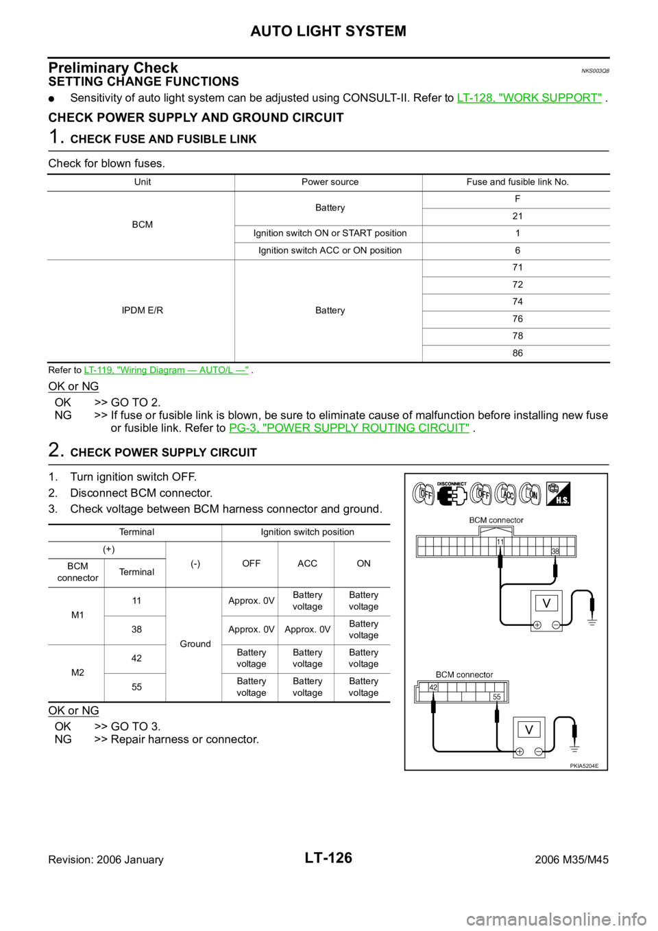
2. CHECK POWER SUPPLY CIRCUIT
1. Turn ignition switch OFF.
2. Disconnect BCM connector.
3. Check voltage between BCM harness connector and ground.
OK or NG
OK >> GO TO 3.
NG >> Repair harness or connector.
Unit Power source Fuse and fusible link No.
BCMBatteryF
21
Ignition switch ON or START position 1
Ignition switch ACC or ON position 6
IPDM E/R Battery71
72
74
76
78
86
Terminal Ignition switch position
(+)
(-) OFF ACC ON
BCM
connectorTerminal
M111
GroundApprox. 0VBattery
voltageBattery
voltage
38 Approx. 0V Approx. 0VBattery
voltage
M242Battery
voltageBattery
voltageBattery
voltage
55Battery
voltageBattery
voltageBattery
voltage
PKIA5204E
Page 4563 of 5621

LT-136
ACTIVE AFS
Revision: 2006 January2006 M35/M45
HEADLAMP AUTO AIMING
Headlamp auto aiming control automatically corrects vertical deviation of light axis that is brought by the
change of vehicle height with changing number of passenger and laden weight, and relieves dazzle to oncom-
ing vehicles.
AFS control unit determines the current vehicle conditions by each received signals, and sends commands to
the low beam headlamps to auto aiming. With the headlamps (HIGH/LOW) illuminated and engine running,
the low beam headlamps are operative by AFS control unit commands.
The height sensor is located on the left side of the rear suspension member and detects rear vehicle height
change by sensing the displacement of the rear suspension arm. And transmits a height sensor signal to the
AFS control unit.
With reference to the rear vehicle height under the empty condition, light axis of low beam with low rear vehi-
cle height is relatively higher than that with the empty condition. AFS control unit switches drive signal corrects
height of low beam axis to maintain height of light axis with empty condition.
Light axis of low beam with high rear vehicle height is relatively lower than that with empty condition. Light axis
of low beam with empty condition is set as upper limit of headlamp auto aiming control operation. Control to
correct deviation is not performed when light axis of low beam gets relatively higher than that with empty con-
dition. Timing of control is switched in accordance with driving conditions.
Headlamp auto aiming operation
*1: Included high beam illuminated
*2: Control timing of drive signal is switched by vehicle speed and accelerating/decelerating vehicle.
*3: Control is performed without regard to the condition of AFS switch. Headlamp auto aiming control function cannot be cancelled.
OUTLINE
Power is supplied
When the ignition switch is ON or START position, power is supplied
through 10A fuse [No.12, located in fuse block (J/B)]
to AFS control unit terminal 1
to front combination lamp LH and RH terminal 13
to AFS switch terminal 1.
Ground is supplied
to AFS control unit terminal 25
through grounds M16 and M70,
to front combination lamp LH and RH terminal 11
through grounds E22 and E43.
SKIB4707E
Operating range With 18-inch wheel (Reference value) With 19-inch wheel (Reference value) Vehicle height
A 0 mm (Standard position) 0 mm (Standard position) Unloaded vehicle position
B Approx. 200 mm (7.9 in) Approx.180 mm (7.1 in) Low
Low beam status Vehicle speed Engine speed AFS switch
Illuminated*
1Control switch by driving conditions*2While engine running
Irrespective*3
Page 4578 of 5621
ACTIVE AFS
LT-151
C
D
E
F
G
H
I
J
L
MA
B
LT
Revision: 2006 January2006 M35/M45
How to Proceed with Trouble DiagnosisNKS003QK
1. Confirm the symptom or customer complaint.
2. Understand operation description and function description. Refer to LT-135, "
System Description" .
3. Perform the preliminary check. Refer to LT- 1 5 1 , "
Preliminary Check" .
4. Perform self-diagnosis by CONSULT-II. Refer to LT-154, "
SELF-DIAG RESULTS" .
5. Check symptom and repair or replace the cause of malfunction.
6. Does the swivel control operate normally? If YES: GO TO 7. If NO: GO TO 4.
7. INSPECTION END
Preliminary CheckNKS003QL
1. CHECK FUSE
Check for blown fuses.
Refer to LT-143, "Wiring Diagram — AFS —" .
OK or NG
OK >> GO TO 2.
NG >> If the fuse is brown be sure to eliminate cause of malfunction before installing new fuse. Refer to
PG-3, "
POWER SUPPLY ROUTING CIRCUIT" .
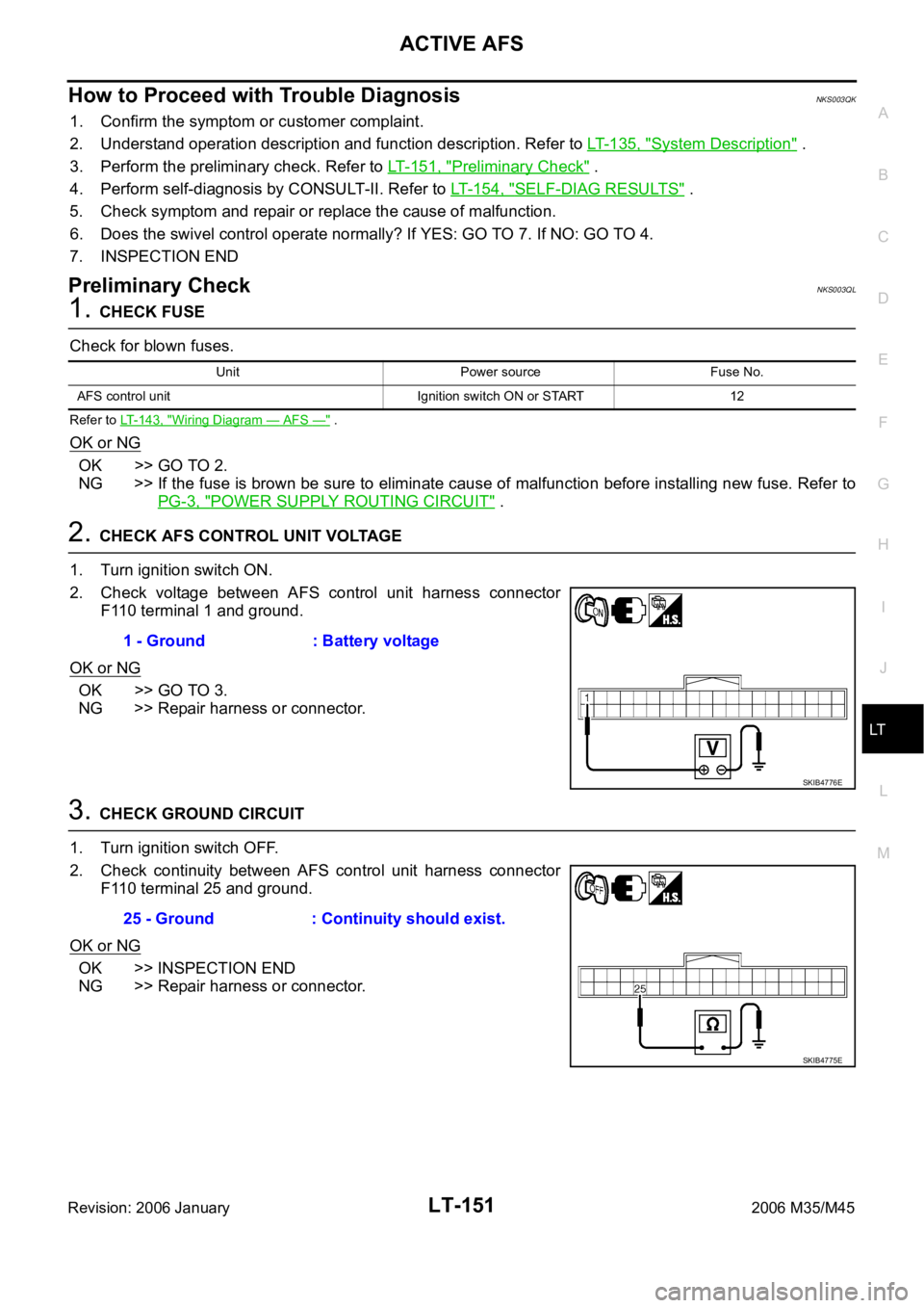
2. CHECK AFS CONTROL UNIT VOLTAGE
1. Turn ignition switch ON.
2. Check voltage between AFS control unit harness connector
F110 terminal 1 and ground.
OK or NG
OK >> GO TO 3.
NG >> Repair harness or connector.
3. CHECK GROUND CIRCUIT
1. Turn ignition switch OFF.
2. Check continuity between AFS control unit harness connector
F110 terminal 25 and ground.
OK or NG
OK >> INSPECTION END
NG >> Repair harness or connector.
Unit Power source Fuse No.
AFS control unit Ignition switch ON or START 12
1 - Ground : Battery voltage
SKIB4776E
25 - Ground : Continuity should exist.
SKIB4775E
Page 4621 of 5621

LT-194
FRONT FOG LAMP
Revision: 2006 January2006 M35/M45
OUTLINE
Power is supplied at all times
through 15A fuse (No. 88, located in IPDM E/R)
to front fog lamp relay, located in IPDM E/R,
through 15A fuse (No. 78, located in IPDM E/R)
to CPU, located in IPDM E/R,
through 15A fuse (No. 71, located in IPDM E/R)
to CPU, located in IPDM E/R,
through 50A fusible link (letter F, located in fuse fusible link and relay block)
to BCM terminal 55,
through 10A fuse [No. 21, located in fuse block (J/B)]
to BCM terminal 42, and
to combination meter terminal 23,
through 10A fuse [No. 19, located in fuse block (J/B)]
to unified meter and A/C amp. terminal 54,
through 10A fuse [No. 22, located in fuse block (J/B)]
to key slot terminal 1.
With the ignition switch in the ON or START position, power is supplied
to CPU, located in IPDM E/R,
through 15A fuse [No. 1, located in fuse block (J/B)]
to BCM terminal 38,
through 10A fuse [No. 14, located in fuse block (J/B)]
to combination meter terminal 12,
through 10A fuse [No. 12, located in fuse block (J/B)]
to unified meter and A/C amp. terminal 53.
With the ignition switch in the ACC or ON position, power is supplied
through 10A fuse [No. 6, located in fuse block (J/B)]
to BCM terminal 11.
Ground is supplied
to BCM terminal 52
to combination meter terminals 9, 10 and 11
to unified meter and A/C amp. terminals 55 and 71
to engine switch (push switch) terminal 1
to key slot terminal 8
through grounds M16 and M70,
to IPDM E/R terminals 38 and 51
through grounds E22 and E43.
Page 4629 of 5621
LT-202
FRONT FOG LAMP
Revision: 2006 January2006 M35/M45
Terminals and Reference Values for IPDM E/RNKS003R9
How to Perform Trouble DiagnosesNKS003RA
1. Confirm the symptom or customer complaint.
2. Understand operation description and function description. Refer to LT- 1 9 3 , "
System Description" .
3. Perform the Preliminary Check. Refer to LT-202, "
Preliminary Check" .
4. Check symptom and repair or replace the cause of malfunction.
5. Does the front fog lamp operate normally? If YES, GO TO 6. If NO, GO TO 4.
6. INSPECTION END
Preliminary CheckNKS003RB
CHECK POWER SUPPLY AND GROUND CIRCUIT
1. CHECK FUSE
Check for blown fuses.
Refer to LT-197, "Wiring Diagram — F/FOG —" .
OK or NG
OK >> GO TO 2.
NG >> If fuse or fusible link is blown, be sure to eliminate cause of malfunction before installing new fuse
or fusible link. Refer to PG-3, "
POWER SUPPLY ROUTING CIRCUIT" .
Terminal
No.Wire
colorSignal nameMeasuring condition
Reference value
Ignition
switchOperation or condition
36 L/Y Front fog lamp (LH) ONLighting switch must be in
the 2ND position or AUTO
position (headlamp is ON)Front fog lamp switch: OFF Approx. 0V
Front fog lamp switch: ON Battery voltage
37 W/R Front fog lamp (RH) ONLighting switch must be in
the 2ND position or AUTO
position (headlamp is ON)Front fog lamp switch: OFF Approx. 0V
Front fog lamp switch: ON Battery voltage
38 B Ground ON — Approx. 0V
49 L CAN
H — — —
50 P CAN
L — — —
51 B Ground ON — Approx. 0V
Unit Power source Fuse and fusible link No.
BCMBatteryF
21
Ignition switch ON or START position 1
Ignition switch ACC or ON position 6
IPDM E/R Battery71
88
78
Page 4630 of 5621
FRONT FOG LAMP
LT-203
C
D
E
F
G
H
I
J
L
MA
B
LT
Revision: 2006 January2006 M35/M45
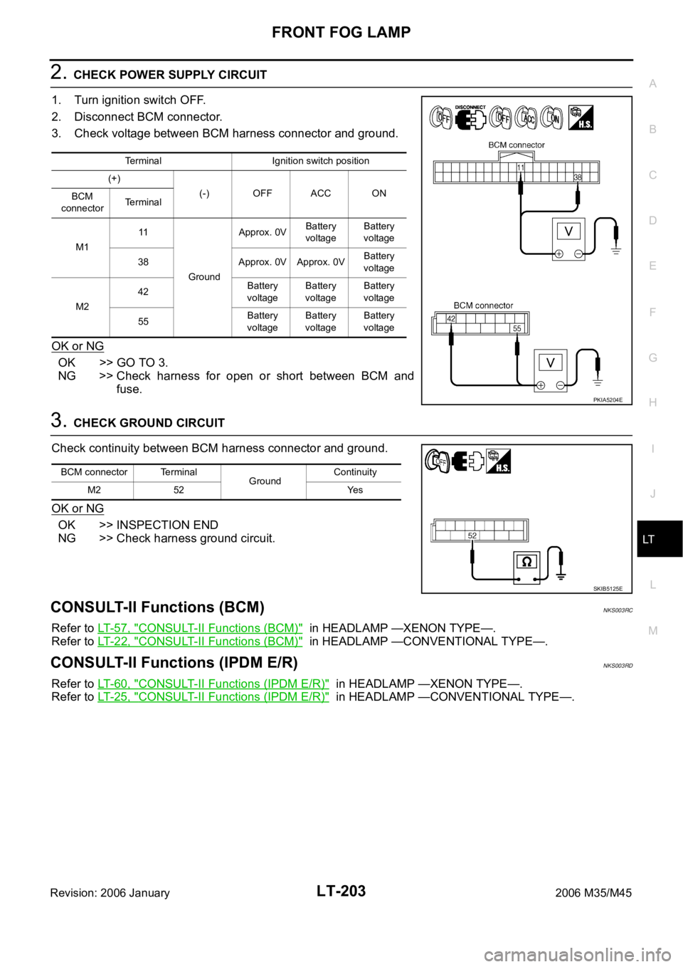
2. CHECK POWER SUPPLY CIRCUIT
1. Turn ignition switch OFF.
2. Disconnect BCM connector.
3. Check voltage between BCM harness connector and ground.
OK or NG
OK >> GO TO 3.
NG >> Check harness for open or short between BCM and
fuse.
3. CHECK GROUND CIRCUIT
Check continuity between BCM harness connector and ground.
OK or NG
OK >> INSPECTION END
NG >> Check harness ground circuit.
CONSULT-II Functions (BCM)NKS003RC
Refer to LT- 5 7 , "CONSULT-II Functions (BCM)" in HEADLAMP —XENON TYPE—.
Refer to LT- 2 2 , "
CONSULT-II Functions (BCM)" in HEADLAMP —CONVENTIONAL TYPE—.
CONSULT-II Functions (IPDM E/R)NKS003RD
Refer to LT- 6 0 , "CONSULT-II Functions (IPDM E/R)" in HEADLAMP —XENON TYPE—.
Refer to LT- 2 5 , "
CONSULT-II Functions (IPDM E/R)" in HEADLAMP —CONVENTIONAL TYPE—.
Terminal Ignition switch position
(+)
(-) OFF ACC ON
BCM
connectorTerminal
M111
GroundApprox. 0VBattery
voltageBattery
voltage
38 Approx. 0V Approx. 0VBattery
voltage
M242Battery
voltageBattery
voltageBattery
voltage
55Battery
voltageBattery
voltageBattery
voltage
PKIA5204E
BCM connector Terminal
GroundContinuity
M2 52 Yes
SKIB5125E
Page 4638 of 5621
TURN SIGNAL AND HAZARD WARNING LAMPS
LT-211
C
D
E
F
G
H
I
J
L
MA
B
LT
Revision: 2006 January2006 M35/M45
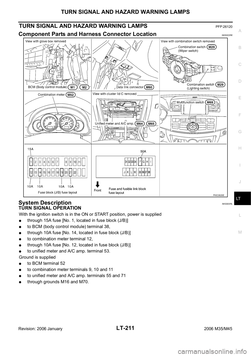
TURN SIGNAL AND HAZARD WARNING LAMPSPFP:26120
Component Parts and Harness Connector LocationNKS003RK
System DescriptionNKS003RL
TURN SIGNAL OPERATION
With the ignition switch is in the ON or START position, power is supplied
through 15A fuse [No. 1, located in fuse block (J/B)]
to BCM (body control module) terminal 38,
through 10A fuse [No. 14, located in fuse block (J/B)]
to combination meter terminal 12,
through 10A fuse [No. 12, located in fuse block (J/B)]
to unified meter and A/C amp. terminal 53.
Ground is supplied
to BCM terminal 52
to combination meter terminals 9, 10 and 11
to unified meter and A/C amp. terminals 55 and 71
through grounds M16 and M70.
PKIC0620E
Page 4639 of 5621

LT-212
TURN SIGNAL AND HAZARD WARNING LAMPS
Revision: 2006 January2006 M35/M45
LH Turn Signal Lamp
When turn signal switch is moved to left position, BCM receives input signal requesting left turn signals to
flash. BCM then supplies power
through BCM terminal 45
to front combination lamp LH (turn signal) terminal 10
to side turn signal lamp LH terminal 1, and
to rear combination lamp LH (turn signal) terminal 3.
Ground is supplied
to front combination lamp LH (turn signal) terminal 9
to side turn signal lamp LH terminal 2
through grounds E22 and E43,
to rear combination lamp LH (turn signal) terminal 4
through grounds B5, B40 and B131.
The BCM also supplies input to unified meter and A/C amp. terminals 56 and 72 across the CAN communica-
tion lines.
The unified meter and A/C amp. which received the turn indicator signal makes the left turn signal indicator
turn on in combination meter.
With power and input supplied, the BCM controls the flashing of the LH turn signal lamps.
RH Turn Signal Lamp
When turn signal switch is moved to right position, BCM receives input signal requesting right turn signals to
flash. BCM then supplies power
through BCM terminal 46
to front combination lamp RH (turn signal) terminal 10
to side turn signal lamp RH terminal 1, and
to rear combination lamp RH (turn signal) terminal 3.
Ground is supplied
to front combination lamp RH (turn signal) terminal 9
to side turn signal lamp RH terminal 2
through grounds E22 and E43,
to rear combination lamp RH (turn signal) terminal 4
through grounds B5, B40 and B131.
The BCM also supplies input to unified meter and A/C amp. terminals 56 and 72 across the CAN communica-
tion lines.
The unified meter and A/C amp. which received the turn indicator signal makes the right turn signal indicator
turn on in combination meter.
With power and input supplied, the BCM controls the flashing of the RH turn signal lamps.
HAZARD LAMP OPERATION
Power is supplied at all times
through 50A fusible link (letter F, located in fuse, fusible link and relay block)
to BCM terminal 55,
through 10A fuse [No. 21, located in fuse block (J/B)]
to BCM terminal 42
to combination meter terminal 23,
through 10A fuse [No. 19, located in fuse block (J/B)]
to unified meter and A/C amp. terminal 54.
When the hazard switch is depressed, ground is supplied
to BCM terminal 29
through multifunction switch terminal 6.
Ground is supplied
to multifunction switch terminal 14