2006 INFINITI M35 battery
[x] Cancel search: batteryPage 1465 of 5621
DI-32
UNIFIED METER AND A/C AMP
Revision: 2006 January2006 M35/M45
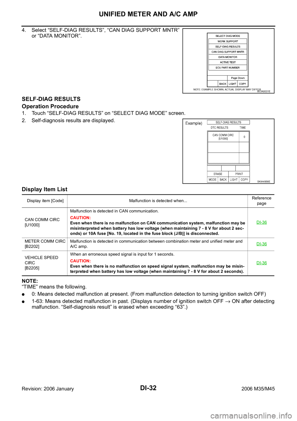
4. Select “SELF-DIAG RESULTS”, “CAN DIAG SUPPORT MNTR”
or “DATA MONITOR”.
SELF-DIAG RESULTS
Operation Procedure
1. Touch “SELF-DIAG RESULTS” on “SELECT DIAG MODE” screen.
2. Self-diagnosis results are displayed.
Display Item List
NOTE:
“TIME” means the following.
0: Means detected malfunction at present. (From malfunction detection to turning ignition switch OFF)
1-63: Means detected malfunction in past. (Displays number of ignition switch OFF ON after detecting
malfunction. “Self-diagnosis result” is erased when exceeding “63”.)
BCIA0031E
SKIA4956E
Display item [Code] Malfunction is detected when...Reference
page
CAN COMM CIRC
[U1000]Malfunction is detected in CAN communication.
CAUTION:
Even when there is no malfunction on CAN communication system, malfunction may be
misinterpreted when battery has low voltage (when maintaining 7 - 8 V for about 2 sec-
onds) or 10A fuse [No. 19, located in the fuse block (J/B)] is disconnected.DI-36
METER COMM CIRC
[B2202]Malfunction is detected in communication between combination meter and unified meter and
A/C amp.DI-36
VEHICLE SPEED
CIRC
[B2205]When an erroneous speed signal is input for 1 seconds.
CAUTION:
Even when there is no malfunction on speed signal system, malfunction may be misin-
terpreted when battery has low voltage (when maintaining 7 - 8 V for about 2 seconds). DI-36
Page 1468 of 5621
UNIFIED METER AND A/C AMP
DI-35
C
D
E
F
G
H
I
J
L
MA
B
DI
Revision: 2006 January2006 M35/M45
Power Supply and Ground Circuit InspectionNKS003UJ
1. CHECK FUSE
Check for blown fuses.
OK or NG
OK >> GO TO 2.
NG >> Be sure to eliminate cause of malfunction before installing new fuse. Refer to PG-3, "
POWER
SUPPLY ROUTING CIRCUIT" .
2. CHECK POWER SUPPLY CIRCUIT
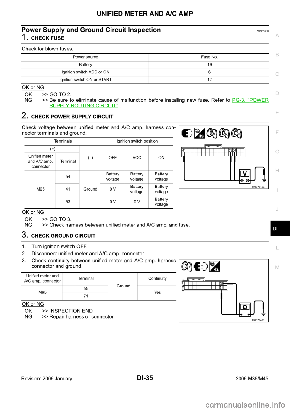
Check voltage between unified meter and A/C amp. harness con-
nector terminals and ground.
OK or NG
OK >> GO TO 3.
NG >> Check harness between unified meter and A/C amp. and fuse.
3. CHECK GROUND CIRCUIT
1. Turn ignition switch OFF.
2. Disconnect unified meter and A/C amp. connector.
3. Check continuity between unified meter and A/C amp. harness
connector and ground.
OK or NG
OK >> INSPECTION END
NG >> Repair harness or connector.
Power source Fuse No.
Battery 19
Ignition switch ACC or ON 6
Ignition switch ON or START 12
Terminals Ignition switch position
(+)
(–) OFF ACC ON Unified meter
a n d A / C a m p .
connectorTerminal
M6554
GroundBattery
voltageBattery
voltageBattery
voltage
41 0 VBattery
voltageBattery
voltage
53 0 V 0 VBattery
voltage
PKIB7645E
Unified meter and
A/C amp. connectorTerminal
GroundContinuity
M6555
Ye s
71
PKIB7646E
Page 1500 of 5621
WARNING CHIME
DI-67
C
D
E
F
G
H
I
J
L
MA
B
DI
Revision: 2006 January2006 M35/M45
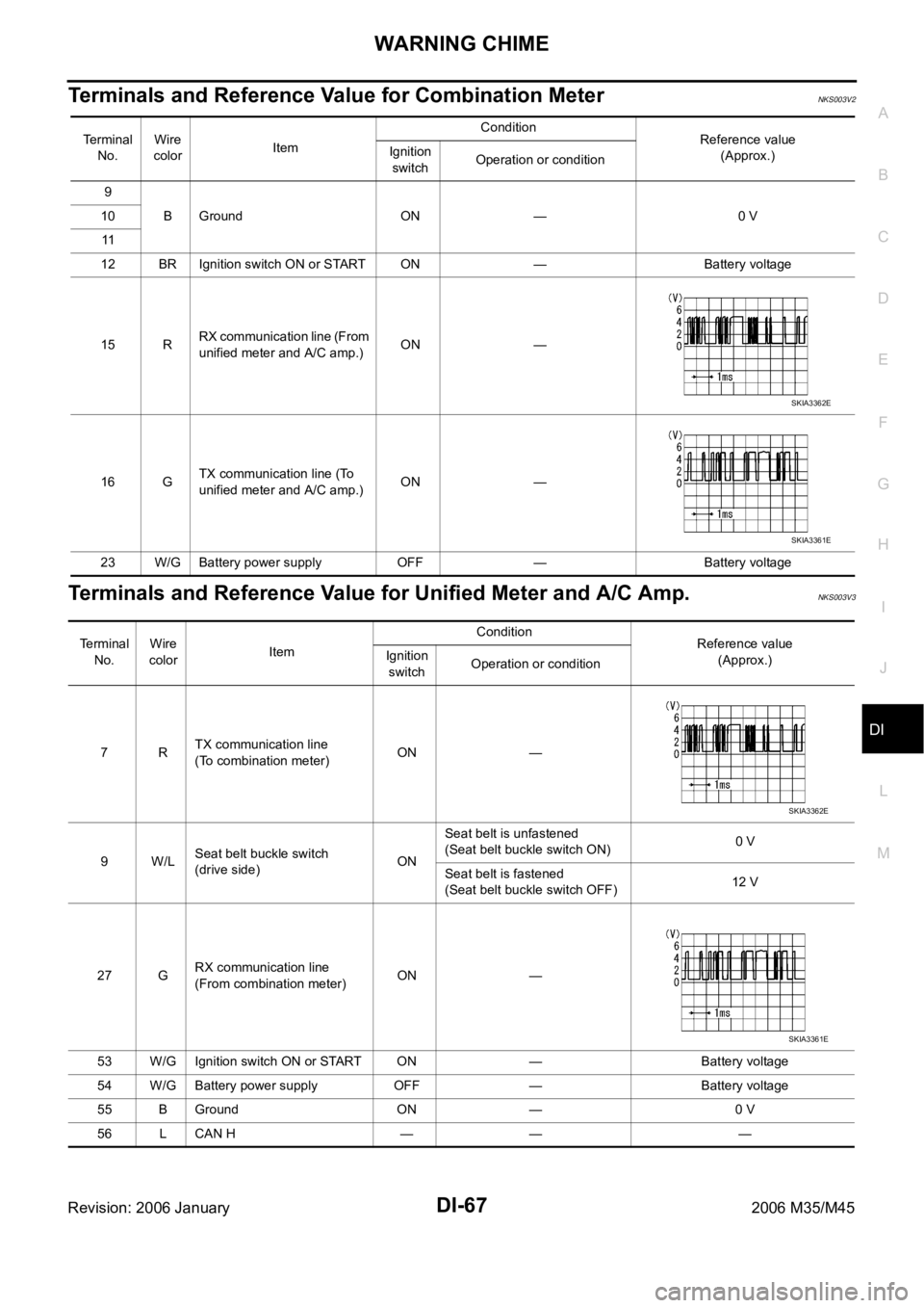
Terminals and Reference Value for Combination MeterNKS003V2
Terminals and Reference Value for Unified Meter and A/C Amp.NKS003V3
Te r m i n a l
No.Wire
colorItemCondition
Reference value
(Approx.) Ignition
switchOperation or condition
9
B Ground ON — 0 V 10
11
12 BR Ignition switch ON or START ON — Battery voltage
15 RRX communication line (From
unified meter and A/C amp.)ON —
16 GTX communication line (To
unified meter and A/C amp.)ON —
23 W/G Battery power supply OFF — Battery voltage
SKIA3362E
SKIA3361E
Terminal
No.Wire
colorItemCondition
Reference value
(Approx.) Ignition
switchOperation or condition
7RTX communication line
(To combination meter)ON —
9W/LSeat belt buckle switch
(drive side)ONSeat belt is unfastened
(Seat belt buckle switch ON)0 V
Seat belt is fastened
(Seat belt buckle switch OFF)12 V
27 GRX communication line
(From combination meter)ON —
53 W/G Ignition switch ON or START ON — Battery voltage
54 W/G Battery power supply OFF — Battery voltage
55 B Ground ON — 0 V
56 L CAN H — — —
SKIA3362E
SKIA3361E
Page 1501 of 5621
DI-68
WARNING CHIME
Revision: 2006 January2006 M35/M45
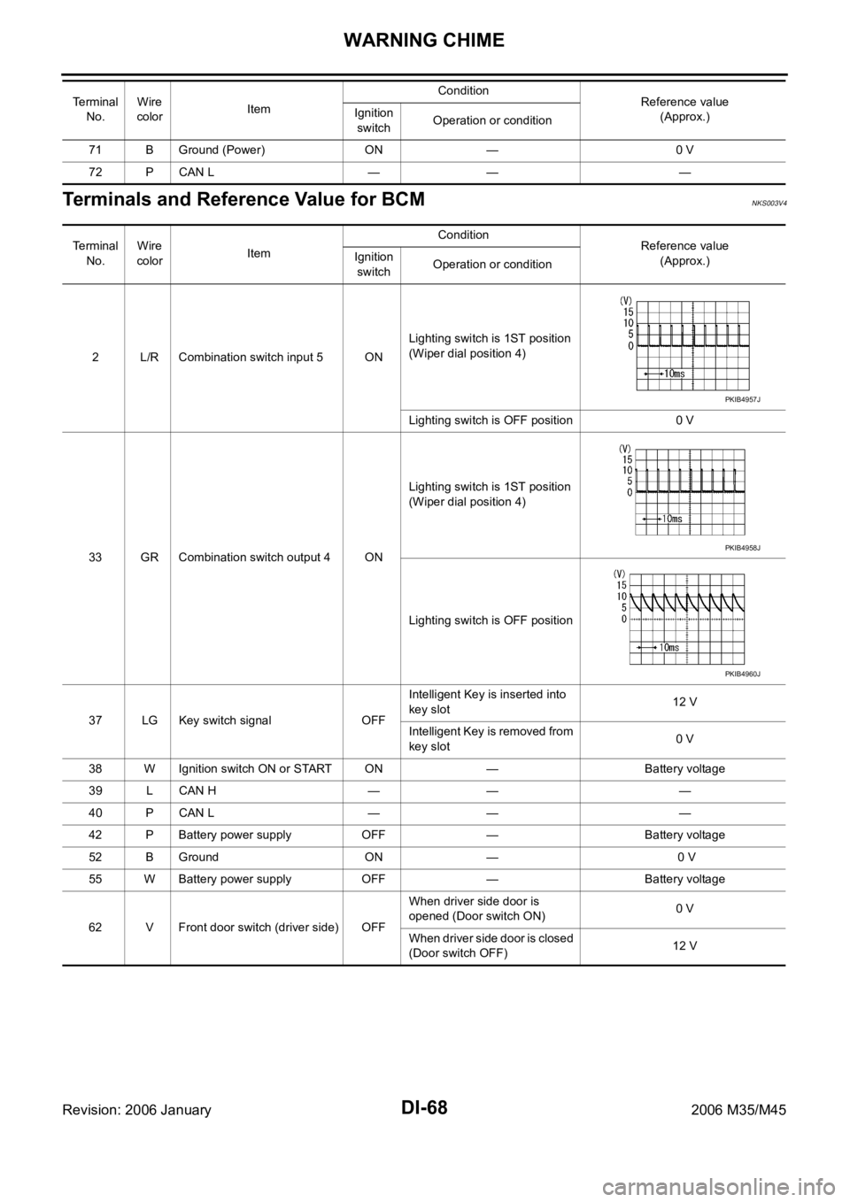
Terminals and Reference Value for BCMNKS003V4
71 B Ground (Power) ON — 0 V
72 P CAN L — — — Te r m i n a l
No.Wire
colorItemCondition
Reference value
(Approx.) Ignition
switchOperation or condition
Te r m i n a l
No.Wire
colorItemCondition
Reference value
(Approx.) Ignition
switchOperation or condition
2 L/R Combination switch input 5 ONLighting switch is 1ST position
(Wiper dial position 4)
Lighting switch is OFF position 0 V
33 GR Combination switch output 4 ONLighting switch is 1ST position
(Wiper dial position 4)
Lighting switch is OFF position
37 LG Key switch signal OFFIntelligent Key is inserted into
key slot12 V
Intelligent Key is removed from
key slot0 V
38 W Ignition switch ON or START ON — Battery voltage
39 L CAN H — — —
40 P CAN L — — —
42 P Battery power supply OFF — Battery voltage
52 B Ground ON — 0 V
55 W Battery power supply OFF — Battery voltage
62 V Front door switch (driver side) OFFWhen driver side door is
opened (Door switch ON)0 V
When driver side door is closed
(Door switch OFF)12 V
PKIB4957J
PKIB4958J
PKIB4960J
Page 1505 of 5621
DI-72
WARNING CHIME
Revision: 2006 January2006 M35/M45
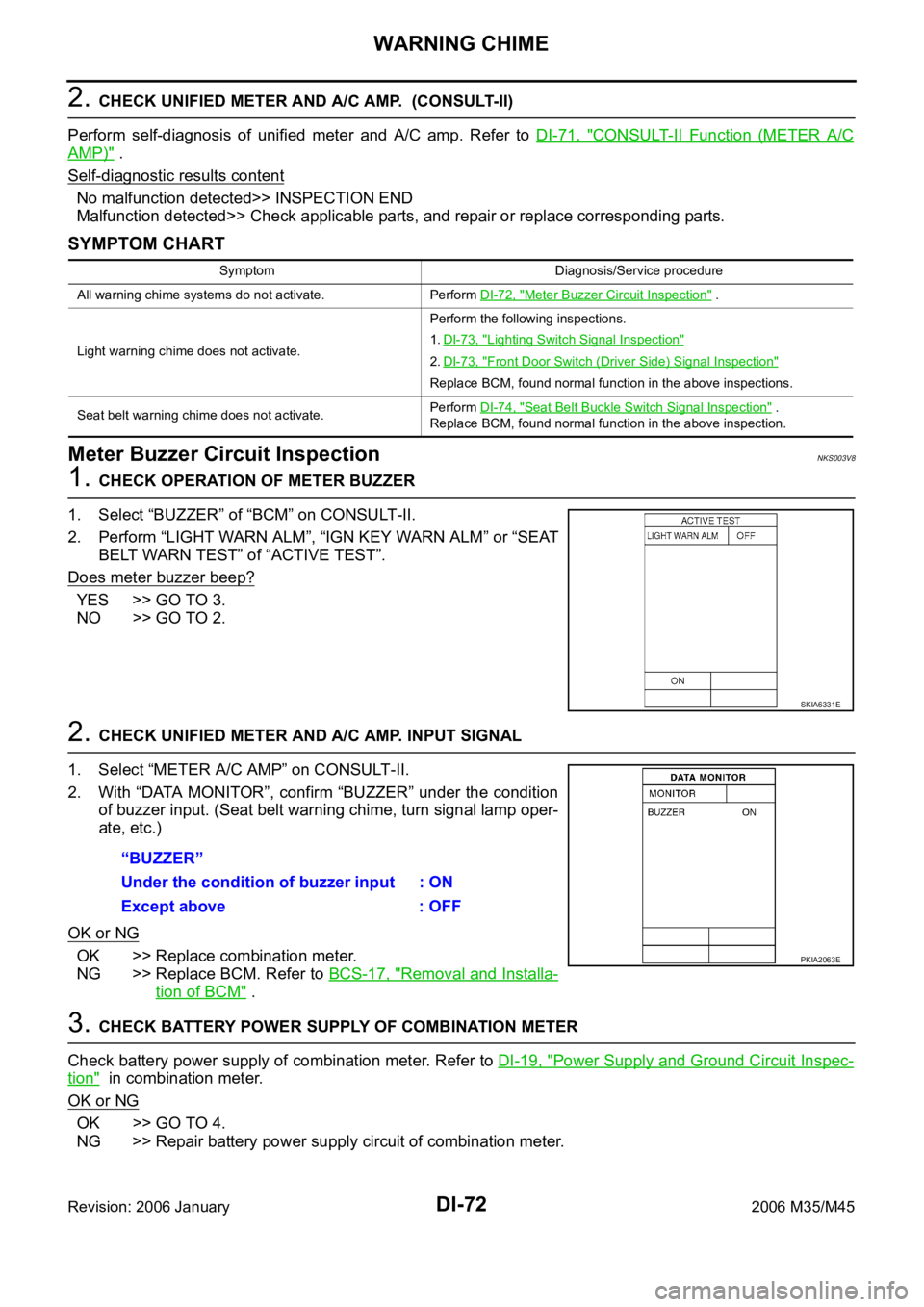
2. CHECK UNIFIED METER AND A/C AMP. (CONSULT-II)
Perform self-diagnosis of unified meter and A/C amp. Refer to DI-71, "
CONSULT-II Function (METER A/C
AMP)" .
Self
-diagnostic results content
No malfunction detected>> INSPECTION END
Malfunction detected>> Check applicable parts, and repair or replace corresponding parts.
SYMPTOM CHART
Meter Buzzer Circuit InspectionNKS003V8
1. CHECK OPERATION OF METER BUZZER
1. Select “BUZZER” of “BCM” on CONSULT-II.
2. Perform “LIGHT WARN ALM”, “IGN KEY WARN ALM” or “SEAT
BELT WARN TEST” of “ACTIVE TEST”.
Does meter buzzer beep?
YES >> GO TO 3.
NO >> GO TO 2.
2. CHECK UNIFIED METER AND A/C AMP. INPUT SIGNAL
1. Select “METER A/C AMP” on CONSULT-II.
2. With “DATA MONITOR”, confirm “BUZZER” under the condition
of buzzer input. (Seat belt warning chime, turn signal lamp oper-
ate, etc.)
OK or NG
OK >> Replace combination meter.
NG >> Replace BCM. Refer to BCS-17, "
Removal and Installa-
tion of BCM" .
3. CHECK BATTERY POWER SUPPLY OF COMBINATION METER
Check battery power supply of combination meter. Refer to DI-19, "
Power Supply and Ground Circuit Inspec-
tion" in combination meter.
OK or NG
OK >> GO TO 4.
NG >> Repair battery power supply circuit of combination meter.
Symptom Diagnosis/Service procedure
All warning chime systems do not activate. Perform DI-72, "
Meter Buzzer Circuit Inspection" .
Light warning chime does not activate.Perform the following inspections.
1.DI-73, "
Lighting Switch Signal Inspection"
2.DI-73, "Front Door Switch (Driver Side) Signal Inspection"
Replace BCM, found normal function in the above inspections.
Seat belt warning chime does not activate.Perform DI-74, "
Seat Belt Buckle Switch Signal Inspection" .
Replace BCM, found normal function in the above inspection.
SKIA6331E
“BUZZER”
Under the condition of buzzer input : ON
Except above : OFF
PKIA2063E
Page 1506 of 5621
WARNING CHIME
DI-73
C
D
E
F
G
H
I
J
L
MA
B
DI
Revision: 2006 January2006 M35/M45
4. CHECK BATTERY POWER SUPPLY OF UNIFIED METER AND A/C AMP.
Check battery power supply of unified meter and A/C amp. Refer to DI-35, "
Power Supply and Ground Circuit
Inspection" in unified meter and A/C amp.
OK or NG
OK >> Replace BCM. Refer to BCS-17, "Removal and Installation of BCM" .
NG >> Repair battery power supply circuit of unified meter and A/C amp.
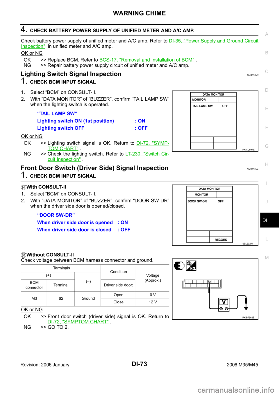
Lighting Switch Signal InspectionNKS003V9
1. CHECK BCM INPUT SIGNAL
1. Select “BCM” on CONSULT-II.
2. With “DATA MONITOR” of “BUZZER”, confirm “TAIL LAMP SW”
when the lighting switch is operated.
OK or NG
OK >> Lighting switch signal is OK. Return to DI-72, "SYMP-
TOM CHART" .
NG >> Check the lighting switch. Refer to LT- 2 3 0 , "
Switch Cir-
cuit Inspection" .
Front Door Switch (Driver Side) Signal InspectionNKS003VA
1. CHECK BCM INPUT SIGNAL
With CONSULT-ll
1. Select “BCM” on CONSULT-II.
2. With “DATA MONITOR” of “BUZZER”, confirm “DOOR SW-DR”
when the driver side door is opened/closed.
Without CONSULT-ll
Check voltage between BCM harness connector and ground.
OK or NG
OK >> Front door switch (driver side) signal is OK. Return to
DI-72, "
SYMPTOM CHART" .
NG >> GO TO 2.“TAIL LAMP SW”
Lighting switch ON (1st position) : ON
Lighting switch OFF : OFF
PKIC0697E
“DOOR SW-DR”
When driver side door is opened : ON
When driver side door is closed : OFF
SEL502W
Terminals
Condition
Voltage
(Approx.) (+)
(–)
BCM
connectorTerminal Driver side door:
M3 62 GroundOpen 0 V
Close 12 V
PKIB7662E
Page 1524 of 5621
LANE DEPARTURE WARNING SYSTEM
DI-91
C
D
E
F
G
H
I
J
L
MA
B
DI
Revision: 2006 January2006 M35/M45
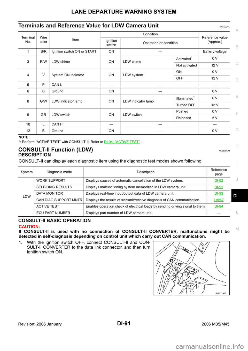
Terminals and Reference Value for LDW Camera UnitNKS003VL
NOTE:
*: Perform “ACTIVE TEST” with CONSULT-II. Refer to DI-94, "
ACTIVE TEST" .
CONSULT-II Function (LDW)NKS003VM
DESCRIPTION
CONSULT-II can display each diagnostic item using the diagnostic test modes shown following.
CONSULT-II BASIC OPERATION
CAUTION:
If CONSULT-II is used with no connection of CONSULT-II CONVERTER, malfunctions might be
detected in self-diagnosis depending on control unit which carry out CAN communication.
1. With the ignition switch OFF, connect CONSULT-II and CON-
SULT-II CONVERTER to the data link connector, and then turn
ignition switch ON.
Terminal
No.Wire
colorItemCondition
Reference value
(Approx.) Ignition
switchOperation or condition
1 B/R Ignition switch ON or START ON — Battery voltage
3R/WLDW chime ONLDW chimeActivated
*0 V
Not activated 12 V
4 V System ON indicator ON LDW systemON 0 V
OFF 12 V
5 P CAN L — — —
6 B Ground ON — 0 V
8 G/W LDW indicator lamp ON LDW indicator lamp Illuminated
*0 V
Turned OFF 12 V
9 GR LDW switch ON LDW switchPushed 0 V
Released 5 V
10 L CAN H — — —
12 B Ground ON — 0 V
System Diagnosis mode DescriptionReference
page
LDWWORK SUPPORT Displays causes of automatic cancellation of the LDW system.DI-92
SELF-DIAG RESULTS Displays malfunctioning system memorized in LDW camera unit.DI-92
DATA MONITOR Displays real-time input/output data of LDW camera unit.DI-93
CAN DIAG SUPPORT MNTR Displays the results of transmit/receive diagnosis of CAN communication.LAN-7
ACTIVE TEST Enables operation check of electrical loads by sending driving signal to them.DI-94
ECU PART NUMBER Displays part number of LDW camera unit. —
SKIB3794E
Page 1529 of 5621
DI-96
LANE DEPARTURE WARNING SYSTEM
Revision: 2006 January2006 M35/M45
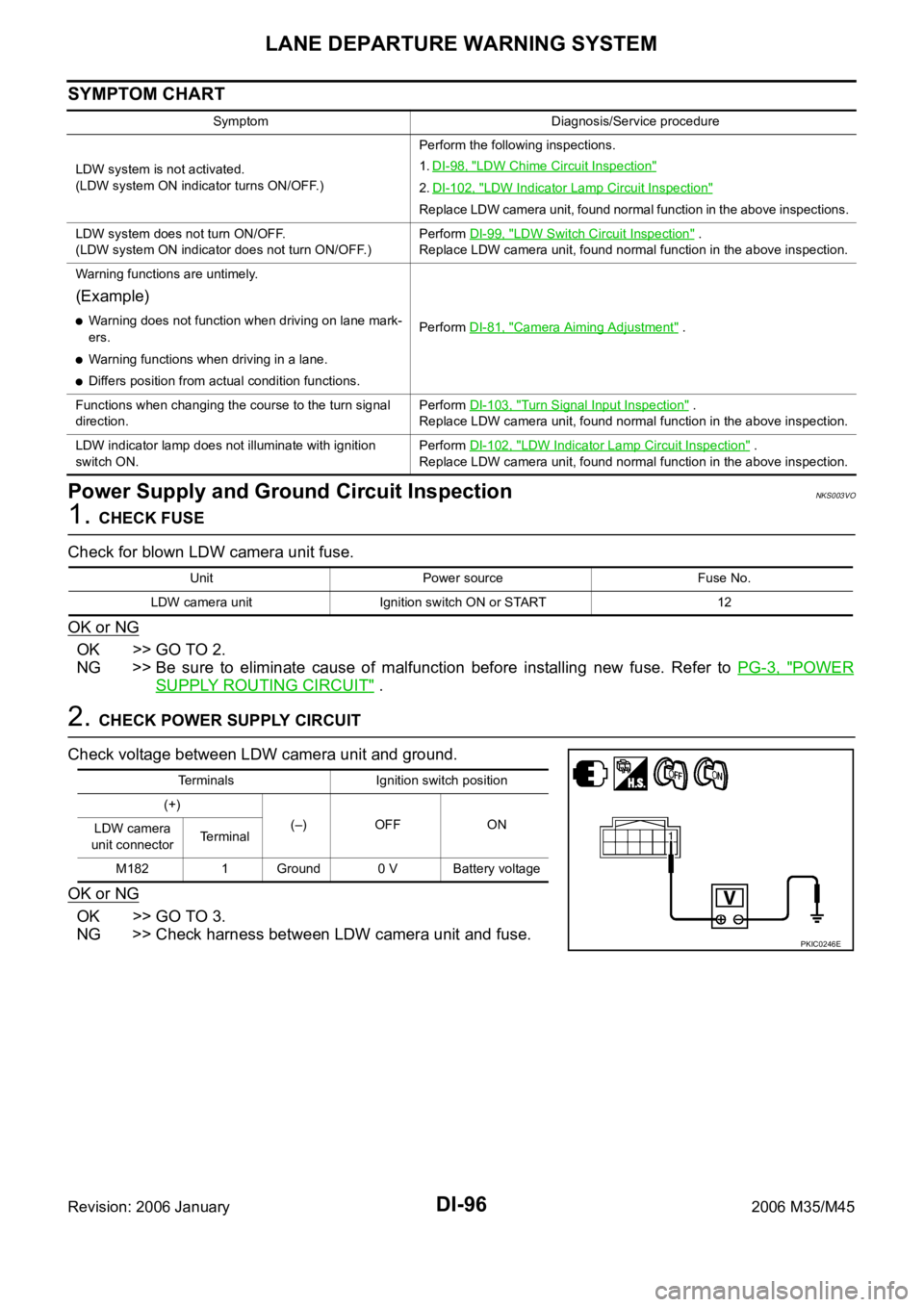
SYMPTOM CHART
Power Supply and Ground Circuit InspectionNKS003VO
1. CHECK FUSE
Check for blown LDW camera unit fuse.
OK or NG
OK >> GO TO 2.
NG >> Be sure to eliminate cause of malfunction before installing new fuse. Refer to PG-3, "
POWER
SUPPLY ROUTING CIRCUIT" .
2. CHECK POWER SUPPLY CIRCUIT
Check voltage between LDW camera unit and ground.
OK or NG
OK >> GO TO 3.
NG >> Check harness between LDW camera unit and fuse.
Symptom Diagnosis/Service procedure
LDW system is not activated.
(LDW system ON indicator turns ON/OFF.)Perform the following inspections.
1.DI-98, "
LDW Chime Circuit Inspection"
2.DI-102, "LDW Indicator Lamp Circuit Inspection"
Replace LDW camera unit, found normal function in the above inspections.
LDW system does not turn ON/OFF.
(LDW system ON indicator does not turn ON/OFF.)Perform DI-99, "
LDW Switch Circuit Inspection" .
Replace LDW camera unit, found normal function in the above inspection.
Warning functions are untimely.
(Example)
Warning does not function when driving on lane mark-
ers.
Warning functions when driving in a lane.
Differs position from actual condition functions.Perform DI-81, "
Camera Aiming Adjustment" .
Functions when changing the course to the turn signal
direction.Perform DI-103, "
Turn Signal Input Inspection" .
Replace LDW camera unit, found normal function in the above inspection.
LDW indicator lamp does not illuminate with ignition
switch ON.Perform DI-102, "
LDW Indicator Lamp Circuit Inspection" .
Replace LDW camera unit, found normal function in the above inspection.
Unit Power source Fuse No.
LDW camera unit Ignition switch ON or START 12
Terminals Ignition switch position
(+)
(–) OFF ON
LDW camera
unit connectorTerminal
M182 1 Ground 0 V Battery voltage
PKIC0246E