Page 1117 of 5621

BL-178
INTELLIGENT KEY SYSTEM/ENGINE START FUNCTION
Revision: 2006 January2006 M35/M45
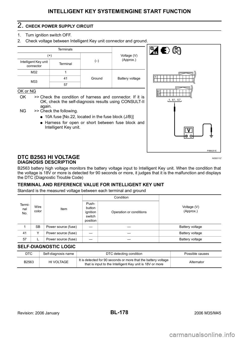
2. CHECK POWER SUPPLY CIRCUIT
1. Turn ignition switch OFF.
2. Check voltage between Intelligent Key unit connector and ground.
OK or NG
OK >> Check the condition of harness and connector. If it is
OK, check the self-diagnosis results using CONSULT-II
again.
NG >> Check the following.
10A fuse [No.22, located in the fuse block (J/B)]
Harness for open or short between fuse block and
Intelligent Key unit.
DTC B2563 HI VOLTAGENIS001YZ
DIAGNOSIS DESCRIPTION
B2563 battery high voltage monitors the battery voltage input to Intelligent Key unit. When the condition that
the voltage is 18V or more is detected for 90 seconds or more, it judges that it is the malfunction and displays
the DTC (Diagnostic Trouble Code)
TERMINAL AND REFERENCE VALUE FOR INTELLIGENT KEY UNIT
Standard is the measured voltage between each terminal and ground
SELF-DIAGNOSTIC LOGIC
Terminals
Voltage (V)
(Approx.) (+)
(–)
Intelligent Key unit
connectorTerminal
M32 1
Ground Battery voltage
M3341
57
PIIB6251E
Te r m i -
nal
No.Wire
colorItemCondition
Voltage (V)
(Approx.) Push-
button
ignition
switch
positionOperation or conditions
1 SB Power source (fuse) — — Battery voltage
41 Y Power source (fuse) — — Battery voltage
57 L Power source (fuse) — — Battery voltage
DTC Self-diagnosis name DTC detecting condition Possible causes
B2563 HI VOLTAGEIt is detected for 90 seconds or more that the battery voltage
that is input to the Intelligent Key unit is 18V or moreAlternator
Page 1130 of 5621

DOOR
BL-191
C
D
E
F
G
H
J
K
L
MA
B
BL
Revision: 2006 January2006 M35/M45
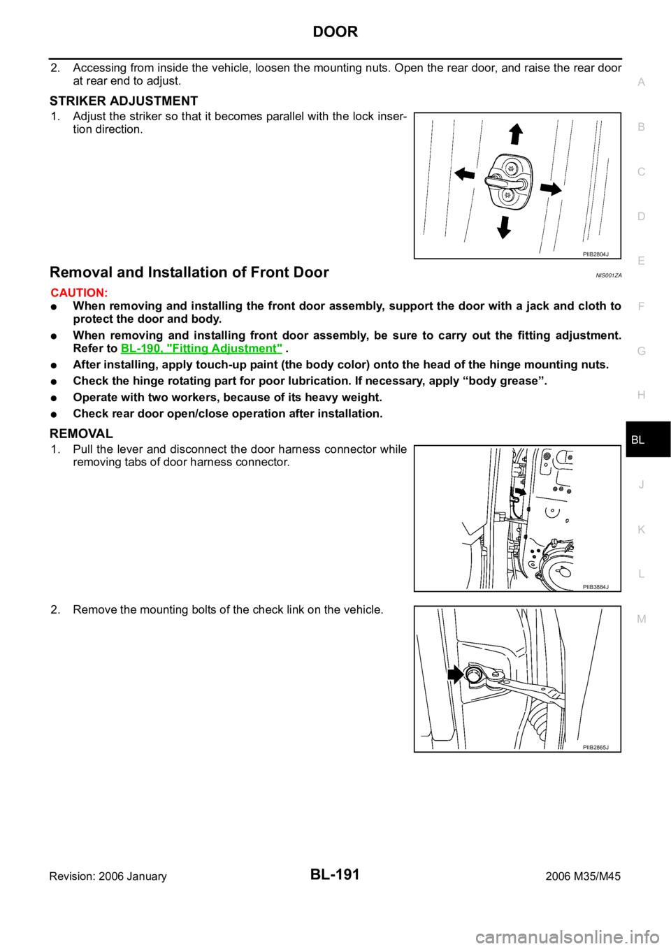
2. Accessing from inside the vehicle, loosen the mounting nuts. Open the rear door, and raise the rear door
at rear end to adjust.
STRIKER ADJUSTMENT
1. Adjust the striker so that it becomes parallel with the lock inser-
tion direction.
Removal and Installation of Front DoorNIS001ZA
CAUTION:
When removing and installing the front door assembly, support the door with a jack and cloth to
protect the door and body.
When removing and installing front door assembly, be sure to carry out the fitting adjustment.
Refer to BL-190, "
Fitting Adjustment" .
After installing, apply touch-up paint (the body color) onto the head of the hinge mounting nuts.
Check the hinge rotating part for poor lubrication. If necessary, apply “body grease”.
Operate with two workers, because of its heavy weight.
Check rear door open/close operation after installation.
REMOVAL
1. Pull the lever and disconnect the door harness connector while
removing tabs of door harness connector.
2. Remove the mounting bolts of the check link on the vehicle.
PIIB2804J
PIIB3884J
PIIB2865J
Page 1135 of 5621
BL-196
FRONT DOOR LOCK
Revision: 2006 January2006 M35/M45
FRONT DOOR LOCKPFP:80502
Component StructureNIS001ZD
Removal and InstallationNIS001ZE
REMOVAL
1. Remove the front door finisher. Refer toEI-34, "Removal and Installation" .
2. Disconnect the inside handle knob cable and lock knob cable
from the back side of the front door finisher.
3. Remove the front door window and front door module assembly. Refer toGW-63, "
FRONT DOOR GLASS
AND REGULATOR" .
4. Remove door side grommet, and remove door key cylinder assembly (driver side) and outside handle
escutcheon (passenger side) bolts (TORX T30) from grommet hole.
1. Outside handle 2. Front gasket 3. Lock knob cable
4. Inside handle 5. Inside handle knob cable 6. Door lock assembly
7. Outside handle cable 8. Key cylinder rod (Driver side only) 9. Outside handle bracket
10. Grommet 11. Rear gasket 12. Door key cylinder assembly (Driver
side)
Outside handle escutcheon (Pas-
senger side)
PIIB5806E
PIIB4933E
Page 1136 of 5621
FRONT DOOR LOCK
BL-197
C
D
E
F
G
H
J
K
L
MA
B
BL
Revision: 2006 January2006 M35/M45
CAUTION:
Do not forcibly remove the TORX bolts (T30).
5. Disconnect door antenna and door request switch connector
and remove harness clamp. (Models with intelligent Key system)
6. Reach to separate the key cylinder rod connection (on the handle).
7. Disconnect door key cylinder switch harness connector.
8. While pulling the outside handle, remove door key cylinder
assembly.
9. Disconnect front door request switch harness connector (with Intelligent Key system).
10. While pulling outside handle, slide toward rear of vehicle to
remove outside handle.
PIIB5808E
PIIB5807E
PIIB5809E
PIIB5810E
Page 1137 of 5621
BL-198
FRONT DOOR LOCK
Revision: 2006 January2006 M35/M45
11. Remove the front gasket and rear gasket.
12. Remove the TORX bolts (T30), remove the door lock assembly.
13. Remove the TORX bolt (T30) of the outside handle bracket.
14. While pulling outside handle bracket, slide toward rear of vehicle
to remove outside handle bracket.
15. Disconnect the door lock actuator connector and remove the door lock assembly.
PIIB5811E
PIIB5812E
PIIB5813E
PIIB5814E
Page 1138 of 5621
FRONT DOOR LOCK
BL-199
C
D
E
F
G
H
J
K
L
MA
B
BL
Revision: 2006 January2006 M35/M45
16. Reach to separate the outside handle cable connection.
INSTALLATION
Install in the reverse order of removal.
CAUTION:
To install each rod, be sure to rotate the rod holder until a click is felt.
PIIB5815E
Page 1139 of 5621
BL-200
REAR DOOR LOCK
Revision: 2006 January2006 M35/M45
REAR DOOR LOCKPFP:82502
Component StructureNIS001ZF
Removal and InstallationNIS001ZG
REMOVAL
1. Remove the rear door finisher. Refer toEI-34, "Removal and Installation" .
2. Disconnect the inside handle knob cable and lock knob cable
from the back side of the rear door finisher.
3. Remove the rear door sash. Refer toGW-67, "
REAR DOOR GLASS AND REGULATOR" .
4. Remove the rear door window and rear door screen assembly. Refer toGW-67, "
REAR DOOR GLASS
AND REGULATOR" .
5. Remove door side grommet, and remove outside handle escutcheon bolt (TORX T30) from grommet
hole.
1. Outside handle 2. Front gasket 3. Inside handle
4. Lock knob cable 5. Inside handle knob cable 6. Door lock assembly
7. Outside handle cable 8. Outside handle bracket 9. Grommet
10. Rear gasket 11. Outside handle escutcheon
PIIB5816E
PIIB4933E
Page 1140 of 5621
REAR DOOR LOCK
BL-201
C
D
E
F
G
H
J
K
L
MA
B
BL
Revision: 2006 January2006 M35/M45
CAUTION:
Do not forcibly remove the TORX bolts (T30).
6. While pulling the outside handle, remove outside handle
escutcheon.
7. While pulling outside handle, slide toward rear of vehicle to
remove outside handle.
8. Remove the front gasket and rear gasket.
PIIB5808E
PIIB5809E
PIIB5810E
PIIB5811E