2006 INFINITI M35 power steering
[x] Cancel search: power steeringPage 3508 of 5621

TOW TRUCK TOWING
GI-45
C
D
E
F
G
H
I
J
K
L
MB
GI
Revision: 2006 January2006 M35/M45
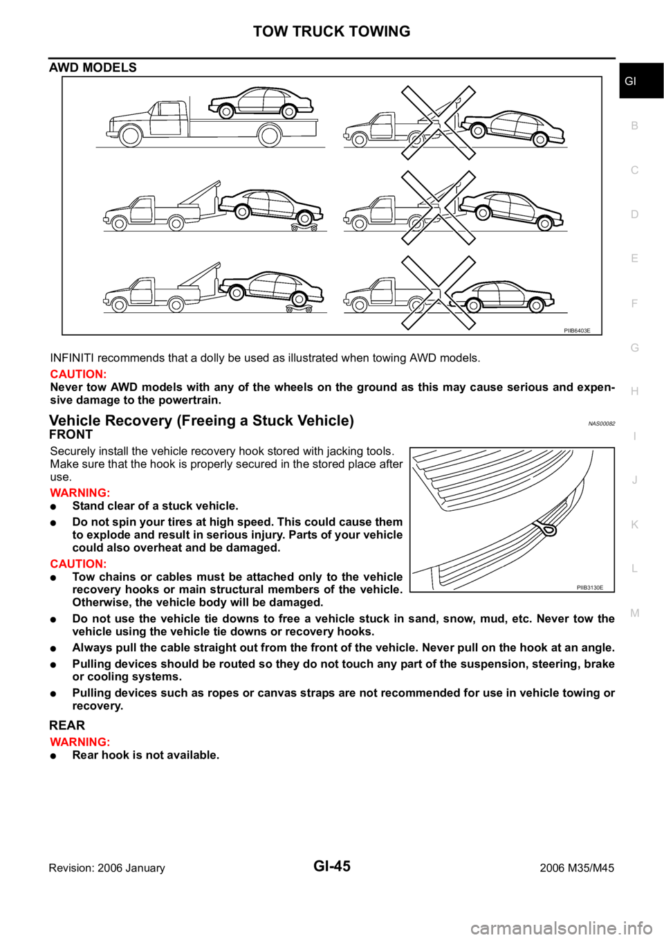
AWD MODELS
INFINITI recommends that a dolly be used as illustrated when towing AWD models.
CAUTION:
Never tow AWD models with any of the wheels on the ground as this may cause serious and expen-
sive damage to the powertrain.
Vehicle Recovery (Freeing a Stuck Vehicle) NAS00082
FRONT
Securely install the vehicle recovery hook stored with jacking tools.
Make sure that the hook is properly secured in the stored place after
use.
WAR NING :
Stand clear of a stuck vehicle.
Do not spin your tires at high speed. This could cause them
to explode and result in serious injury. Parts of your vehicle
could also overheat and be damaged.
CAUTION:
Tow chains or cables must be attached only to the vehicle
recovery hooks or main structural members of the vehicle.
Otherwise, the vehicle body will be damaged.
Do not use the vehicle tie downs to free a vehicle stuck in sand, snow, mud, etc. Never tow the
vehicle using the vehicle tie downs or recovery hooks.
Always pull the cable straight out from the front of the vehicle. Never pull on the hook at an angle.
Pulling devices should be routed so they do not touch any part of the suspension, steering, brake
or cooling systems.
Pulling devices such as ropes or canvas straps are not recommended for use in vehicle towing or
recovery.
REAR
WAR NING :
Rear hook is not available.
PIIB6403E
PIIB3130E
Page 3647 of 5621

IDX-6
ALPHABETICAL INDEX
Meter ..................................................................... DI-5
METER - Wiring diagram .................................... DI-13
MIL data link connectors circuit ....... EC-722, EC-1459
MIL/DL - Wiring diagram .................. EC-722, EC-1459
MIRROR - Wiring diagram ................................ GW-99
Mirror, door ..................................................... GW-120
Mirror, out side ................................................ GW-120
Misfire .............................................. EC-361, EC-1084
MMSW - Wiring diagram .................................. AT-168
Mode door control linkage adjustment ATC-79, ATC-82
Mode door motor .............. ATC-75, ATC-80, ATC-140
Molding - See Exterior .............................. EI-25, EI-29
Mud guard - See Exterior .................................... EI-22
Multiport fuel injection (MFI) system .... EC-31, EC-741
Multiport fuel injection precautions ....................... GI-7
N
NATS - Wiring diagram .................................... BL-256
NONDTC - Wiring diagram .............................. AT-187
NVH troubleshooting (EM) .............................. EM-171
NVH troubleshooting (EM)(VQ35DE) ............... EM-12
NVH troubleshooting (Final drive) ......... FFD-6, RFD-7
NVH troubleshooting (Propeller shaft) ................. PR-3
NVH troubleshooting (Transfer) ........................... TF-8
NVIS (Nissan vehicle immobilizer system) precautions
GI-3
O
O2H2B1 - Wiring diagram .................. EC-191
, EC-913
O2H2B2 - Wiring diagram .................. EC-193, EC-915
O2S2B1 - Wiring diagram .. EC-289, EC-300, EC-313,
EC-1012
, EC-1023, EC-1036
O2S2B2 - Wiring diagram .. EC-291, EC-302, EC-315,
EC-1014
, EC-1025, EC-1038
Oil cooler (engine)(VQ35DE) ............................. LU-14
Oil filter(VK45DE) .............................................. LU-29
Oil filter(VQ35DE) .............................................. LU-10
Oil pan (engine)(VK45DE) .............................. EM-187
Oil pan (engine)(VQ35DE) ................................ EM-29
Oil pressure (engine)(VK45DE) ......................... LU-26
Oil pressure (engine)(VQ35DE) ........................... LU-8
Oil pressure relief valve (engine)(VQ35DE) ........ LU-6
Oil pump (A/T) ................................................. AT-318
Oil pump (engine)(VK45DE) .............................. LU-30
Oil pump (engine)(VQ35DE) .............................. LU-18
Oil pump regulator valve (engine)(VK45DE) ..... LU-30
Oil pump regulator valve (engine)(VQ35DE) ..... LU-18
Oil seal replacement (engine)(VK45DE) ......... EM-229
Oil seal replacement (engine)(VQ35DE) .......... EM-98
Oil seal replacement (front of final drive) .......... FFD-9,
RFD-10
Oil seal replacement (side of final drive) ......... FFD-11,
RFD-14
On board diagnostic system ................ EC-54, EC-764
ORVR (On-board Refueling Vapor Recovery) .. EC-46,
EC-756
Out side mirror ................................................ GW-120
Overheat ......................................... EC-512, EC-1239
P
P/SCKT - Wiring diagram ................................ WW-51
Park/Neutral position switch ........... EC-504, EC-1223
Park/neutral position switch (A/T) .................... AT-113
Parking brake control ........................................... PB-3
Parking lamp .................................................... LT-249
PCV (positive crankcase ventilation) .. EC-51, EC-761
PGC/V - Wiring diagram .. EC-414, EC-422, EC-1134,
EC-1142
PHASE - Wiring diagram ............................... EC-1108
PHSB1 - Wiring diagram .................................. EC-385
PHSB2 - Wiring diagram .................................. EC-387
Pilot bushing replacement - See Pilot
converter(VQ35DE) ........................................ EM-124
Piston assembly(VK45DE) ............................. EM-260
Piston assembly(VQ35DE) ............................. EM-135
Piston pin inspection(VK45DE) ....................... EM-266
Piston pin inspection(VQ35DE) ...................... EM-140
Piston ring inspection(VK45DE) ..................... EM-267
Piston ring inspection(VQ35DE) ..................... EM-141
Piston to bore clearance(VK45DE) ................. EM-270
Piston to bore clearance(VQ35DE) ................ EM-144
PNP/SW - Wiring diagram . EC-506, EC-1225, AT-114
POS - Wiring diagram ..................... EC-378, EC-1101
POWER - Wiring diagram ................................... PG-5
Power door mirror .............................................. BL-24
Power socket ................................................... WW-51
Power steering fluid level ........................ PS-8, MA-37
Power steering gear ........................................... PS-18
Power steering hydraulic pressure .................... PS-29
Power steering oil pump .................................... PS-29
Power steering system bleeding .......................... PS-8
Power supply routing .......................................... PG-3
Power window .................................................. GW-13
PRE/SE - Wiring diagram EC-445, EC-452, EC-1165,
EC-1172
Precations for Leak detection dye .................. ATC-15
Precautions (General) ........................................... GI-4
Pressure switch 1 .............................. AT-153, AT-172
Pressure switch 2 ............................................ AT-165
Pressure switch 3 .............................. AT-149, AT-174
Pressure switch 5 .............................. AT-157, AT-176
Pressure switch 6 .............................. AT-161, AT-178
Pressure test (A/T) ............................................. AT-55
Propeller shaft ........................................... PR-4, PR-6
Propeller shaft on vehicle service ............. PR-4, PR-6
Propeller shaft vibration ............................ PR-4, PR-6
PS/SEN - Wiring diagram ............... EC-488, EC-1207
R
Radiator(VK45DE) ............................................ CO-43
Radiator(VQ35DE) ............................................ CO-14
Rear axle .......................................................... RAX-5
Rear bumper ....................................................... EI-14
Rear combination lamp removal and installation ..........
Page 3662 of 5621

INSTRUMENT PANEL ASSEMBLY
IP-13
C
D
E
F
G
H
J
K
L
MA
B
IP
Revision: 2006 January2006 M35/M45
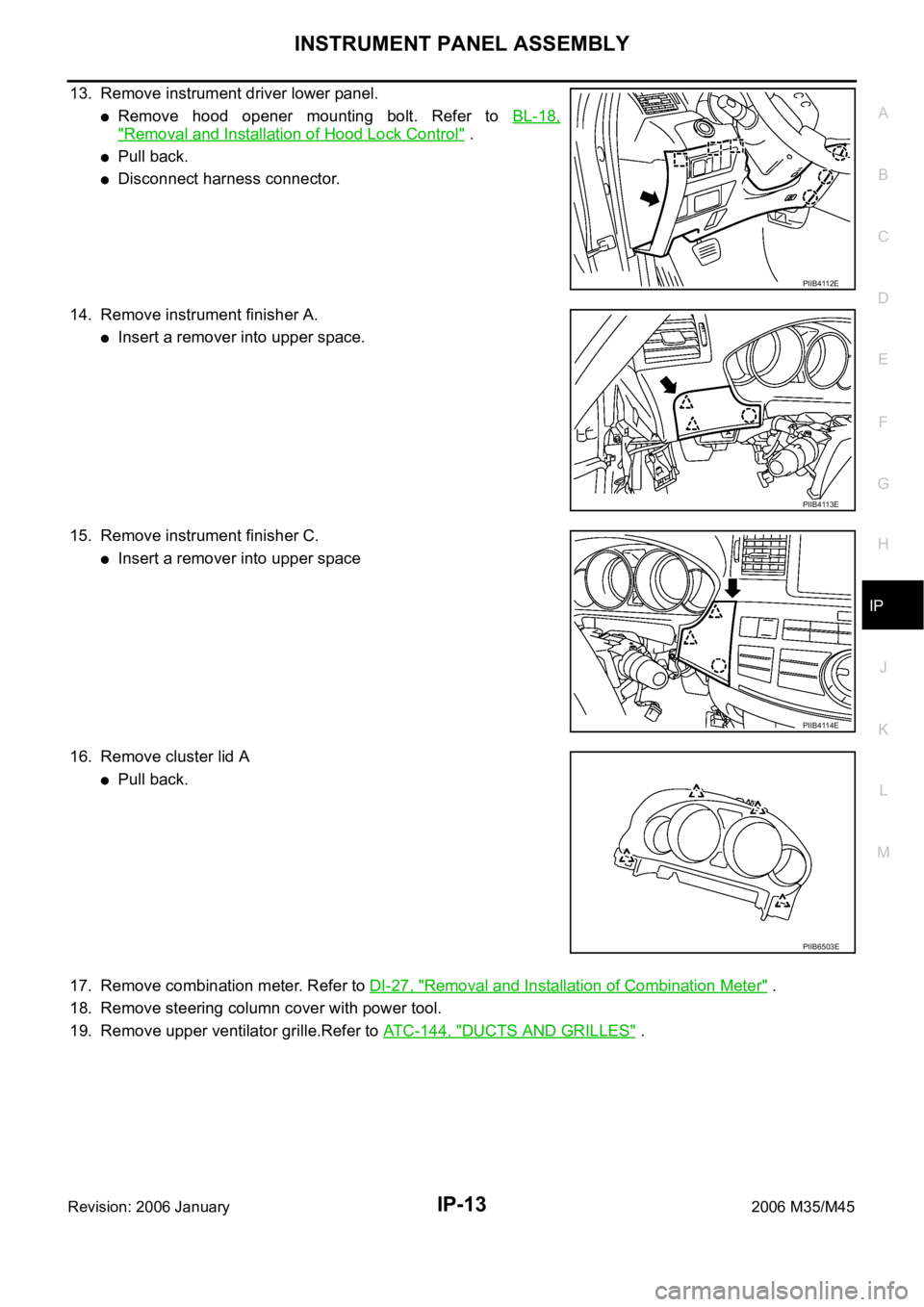
13. Remove instrument driver lower panel.
Remove hood opener mounting bolt. Refer to BL-18,
"Removal and Installation of Hood Lock Control" .
Pull back.
Disconnect harness connector.
14. Remove instrument finisher A.
Insert a remover into upper space.
15. Remove instrument finisher C.
Insert a remover into upper space
16. Remove cluster lid A
Pull back.
17. Remove combination meter. Refer to DI-27, "
Removal and Installation of Combination Meter" .
18. Remove steering column cover with power tool.
19. Remove upper ventilator grille.Refer to ATC-144, "
DUCTS AND GRILLES" .
PIIB4112E
PIIB4113E
PIIB4114E
PIIB6503E
Page 3709 of 5621
![INFINITI M35 2006 Factory Service Manual LAN-40
[CAN]
CAN COMMUNICATION
Revision: 2006 January2006 M35/M45
INPUT/OUTPUT SIGNAL CHART
2WD models
T: Transmit R: Receive
Signals
ECM
TCM
AFS control unit*1
BCM
LDW camera unit*2
Low tire pressu INFINITI M35 2006 Factory Service Manual LAN-40
[CAN]
CAN COMMUNICATION
Revision: 2006 January2006 M35/M45
INPUT/OUTPUT SIGNAL CHART
2WD models
T: Transmit R: Receive
Signals
ECM
TCM
AFS control unit*1
BCM
LDW camera unit*2
Low tire pressu](/manual-img/42/57023/w960_57023-3708.png)
LAN-40
[CAN]
CAN COMMUNICATION
Revision: 2006 January2006 M35/M45
INPUT/OUTPUT SIGNAL CHART
2WD models
T: Transmit R: Receive
Signals
ECM
TCM
AFS control unit*1
BCM
LDW camera unit*2
Low tire pressure warning control unit
Steering angle sensor
Intelligent Key unit
Unified meter and A/C amp.
AV (NAVI) control unit
RAS control unit*3
Pre-crash seat belt control unit*4
Driver seat control unit
ABS actuator and electric unit (control unit)
ICC sensor integrated unit*5
IPDM E/R
A/C compressor request signal TR
Accelerator pedal position signal T R R R
ASCD CRUISE lamp signal T R
ASCD OD cancel request signal T R
ASCD operation signal T R
ASCD SET lamp signal T R
Battery voltage signal T R
Closed throttle position signal T R R
Cooling fan speed request signal TR
Engine coolant temperature signal T R
Engine speed signal T R R R R R R
Engine status signal T R R R
Fuel consumption monitor signal T R R
ICC brake switch signal T R
ICC prohibition signal T R
ICC steering switch signal T R
Malfunctioning indicator lamp signal T R
Power generation command value signal TR
Wide open throttle position signal T R
A/T CHECK indicator lamp signal T R
A/T position indicator signal T R R R R
A/T self-diagnosis signal R T
Current gear position signal T R R
Manual mode indicator signal T R R
N range signal T R R
Output shaft revolution signal R T R R
P range signal T R R R R
R range signal T R R R
Turbine revolution signal R T R
AFS OFF indicator signal T R
A/C switch signal R T
ACC signal T R R
Page 3710 of 5621
![INFINITI M35 2006 Factory Service Manual CAN COMMUNICATION
LAN-41
[CAN]
C
D
E
F
G
H
I
J
L
MA
B
LAN
Revision: 2006 January2006 M35/M45
Blower fan motor switch signal R T
Buzzer output signalTR
TR
RT
Day time running light request signal T R
D INFINITI M35 2006 Factory Service Manual CAN COMMUNICATION
LAN-41
[CAN]
C
D
E
F
G
H
I
J
L
MA
B
LAN
Revision: 2006 January2006 M35/M45
Blower fan motor switch signal R T
Buzzer output signalTR
TR
RT
Day time running light request signal T R
D](/manual-img/42/57023/w960_57023-3709.png)
CAN COMMUNICATION
LAN-41
[CAN]
C
D
E
F
G
H
I
J
L
MA
B
LAN
Revision: 2006 January2006 M35/M45
Blower fan motor switch signal R T
Buzzer output signalTR
TR
RT
Day time running light request signal T R
Door lock/unlock status signal T R
Door switch signal T R R R R R
Door unlock signal T R
Front fog light request signal T R R
Front wiper request signal T R R
High beam request signal T R R
Ignition switch ON signal T R R
Ignition switch signal T R R
Key ID signal T R
Key switch signal T R
Low beam request signal T R
Position light request signal T R R
Rear window defogger switch signal T R
Sleep wake up signal T R R R R
Starter request signal T R
Theft warning horn request signal T R
Trunk switch signal T R R
Turn indicator signal T R R
Tire pressure data signal T R
Tire pressure signal T R R
Steering angle sensor signal R T R R
Door lock/unlock trunk open request signal R T
Hazard and horn request signal R T
Key warning signalTR
Meter display signalTR
RT
Panic alarm request signal R T
Power window open request signal R T
A/C evaporator temperature signal R TSignals
ECM
TCM
AFS control unit*1
BCM
LDW camera unit*2
Low tire pressure warning control unit
Steering angle sensor
Intelligent Key unit
Unified meter and A/C amp.
AV (NAVI) control unit
RAS control unit*3
Pre-crash seat belt control unit*4
Driver seat control unit
ABS actuator and electric unit (control unit)
ICC sensor integrated unit*5
IPDM E/R
Page 3713 of 5621
![INFINITI M35 2006 Factory Service Manual LAN-44
[CAN]
CAN COMMUNICATION
Revision: 2006 January2006 M35/M45
AW D m o del s
T: Transmit R: Receive
Signals
ECM
TCM
AWD control unit
AFS control unit*1
BCM
LDW camera unit*2
Low tire pressure w INFINITI M35 2006 Factory Service Manual LAN-44
[CAN]
CAN COMMUNICATION
Revision: 2006 January2006 M35/M45
AW D m o del s
T: Transmit R: Receive
Signals
ECM
TCM
AWD control unit
AFS control unit*1
BCM
LDW camera unit*2
Low tire pressure w](/manual-img/42/57023/w960_57023-3712.png)
LAN-44
[CAN]
CAN COMMUNICATION
Revision: 2006 January2006 M35/M45
AW D m o del s
T: Transmit R: Receive
Signals
ECM
TCM
AWD control unit
AFS control unit*1
BCM
LDW camera unit*2
Low tire pressure warning control unit
Steering angle sensor
Intelligent Key unit
Unified meter and A/C amp.
AV (NAVI) control unit
Pre-crash seat belt control unit*3
Driver seat control unit
ABS actuator and electric unit (control unit)
ICC sensor integrated unit*4
IPDM E/R
A/C compressor request signal TR
Accelerator pedal position signal T R R R R
ASCD CRUISE lamp signal T R
ASCD OD cancel request signal T R
ASCD operation signal T R
ASCD SET lamp signal T R
Battery voltage signal T R
Closed throttle position signal T R R
Cooling fan speed request signal TR
Engine coolant temperature signal T R
Engine speed signal T R R R R R R
Engine status signal T R R R
Fuel consumption monitor signal T R R
ICC brake switch signal T R
ICC prohibition signal T R
ICC steering switch signal T R
Malfunctioning indicator lamp signal T R
Power generation command value signal TR
Wide open throttle position signal T R
A/T CHECK indicator lamp signal T R
A/T position indicator signal T R R R R
A/T self-diagnosis signal R T
Current gear position signal T R R
Manual mode indicator signal T R R
N range signal T R R
Output shaft revolution signal R T R R
P range signal T R R R R
R range signal T R R R
Turbine revolution signal R T R
AWD signal T R
AWD warning lamp signal T R
AFS OFF indicator signal T R
A/C switch signal R T
Page 3714 of 5621
![INFINITI M35 2006 Factory Service Manual CAN COMMUNICATION
LAN-45
[CAN]
C
D
E
F
G
H
I
J
L
MA
B
LAN
Revision: 2006 January2006 M35/M45
ACC signal T R R
Blower fan motor switch signal R T
Buzzer output signalTR
TR
RT
Day time running light req INFINITI M35 2006 Factory Service Manual CAN COMMUNICATION
LAN-45
[CAN]
C
D
E
F
G
H
I
J
L
MA
B
LAN
Revision: 2006 January2006 M35/M45
ACC signal T R R
Blower fan motor switch signal R T
Buzzer output signalTR
TR
RT
Day time running light req](/manual-img/42/57023/w960_57023-3713.png)
CAN COMMUNICATION
LAN-45
[CAN]
C
D
E
F
G
H
I
J
L
MA
B
LAN
Revision: 2006 January2006 M35/M45
ACC signal T R R
Blower fan motor switch signal R T
Buzzer output signalTR
TR
RT
Day time running light request signal T R
Door lock/unlock status signal T R
Door switch signal T R R R R R
Door unlock signal T R
Front fog light request signal T R R
Front wiper request signal T R R
High beam request signal T R R
Ignition switch ON signal T R R
Ignition switch signal T R R
Key ID signal T R
Key switch signal T R
Low beam request signal T R
Position light request signal T R R
Rear window defogger switch signal T R
Sleep wake up signal T R R R R
Starter request signal T R
Theft warning horn request signal T R
Trunk switch signal T R R
Turn indicator signal T R R
Tire pressure data signal T R
Tire pressure signal T R R
Steering angle sensor signal R T R
Door lock/unlock trunk open request signal R T
Hazard and horn request signal R T
Key warning signalTR
Meter display signalTR
RT
Panic alarm request signal R T
Power window open request signal R TSignals
ECM
TCM
AWD control unit
AFS control unit*1
BCM
LDW camera unit*2
Low tire pressure warning control unit
Steering angle sensor
Intelligent Key unit
Unified meter and A/C amp.
AV (NAVI) control unit
Pre-crash seat belt control unit*3
Driver seat control unit
ABS actuator and electric unit (control unit)
ICC sensor integrated unit*4
IPDM E/R
Page 3845 of 5621
![INFINITI M35 2006 Factory Service Manual LAN-176
[CAN]
CAN SYSTEM (TYPE 3)
Revision: 2006 January2006 M35/M45
19. CHECK SYMPTOM
1. Fill in described symptoms on the column “Symptom” in the check sheet.
2. Connect all connectors, and then INFINITI M35 2006 Factory Service Manual LAN-176
[CAN]
CAN SYSTEM (TYPE 3)
Revision: 2006 January2006 M35/M45
19. CHECK SYMPTOM
1. Fill in described symptoms on the column “Symptom” in the check sheet.
2. Connect all connectors, and then](/manual-img/42/57023/w960_57023-3844.png)
LAN-176
[CAN]
CAN SYSTEM (TYPE 3)
Revision: 2006 January2006 M35/M45
19. CHECK SYMPTOM
1. Fill in described symptoms on the column “Symptom” in the check sheet.
2. Connect all connectors, and then make sure that the symptom is reproduced.
OK or NG
OK >> GO TO 20.
NG >> Refer to LAN-18, "
Example of Filling in Check Sheet When Initial Conditions Are Not Reproduced"
.
20. CHECK UNIT REPRODUCIBILITY
Performs the following procedure for each unit, and then perform reproducibility test.
1. Turn ignition switch OFF.
2. Disconnect the battery cable from the negative terminal.
3. Disconnect the unit connector.
4. Connect the battery cable to the negative terminal.
5. Make sure that the symptom filled in the “Symptom” of the check sheet is reproduced. (Do not confuse it
with the symptom related to removed unit.)
6. Make sure that the same symptom is reproduced.
–A/T assembly
–AFS control unit
–BCM
–Low tire pressure warning control unit
–Steering angle sensor
–Intelligent Key unit
–Unified meter and A/C amp.
–AV control unit
–Pre-crash seat belt control unit
–Driver seat control unit
–ABS actuator and electric unit (control unit)
–ECM
–IPDM E/R
Check results
Reproduce>>Install removed unit, and then check the other unit.
Not reproduced>>Replace removed unit.
IPDM E/R Ignition Relay Circuit InspectionNKS003ZQ
Check the following. If no malfunction is found, replace the IPDM E/R.
IPDM E/R power supply circuit. Refer to PG-30, "Check IPDM E/R Power Supply and Ground Circuit" .
Ignition power supply circuit. Refer to PG-12, "IGNITION POWER SUPPLY — IGNITION SW. IN “ON”
AND/OR “START”" .