2006 INFINITI M35 Fuse
[x] Cancel search: FusePage 3496 of 5621

SERVICE INFORMATION FOR ELECTRICAL INCIDENT
GI-33
C
D
E
F
G
H
I
J
K
L
MB
GI
Revision: 2006 January2006 M35/M45
no voltage; short is further down the circuit than SW1.
With SW1 closed, relay and solenoid disconnected and the DMM leads across both fuse terminals, check
for voltage.
voltage; short is between SW1 and the relay (point B).
no voltage; short is further down the circuit than the relay.
With SW1 closed, relay contacts jumped with fused jumper wire check for voltage.
voltage; short is down the circuit of the relay or between the relay and the disconnected solenoid (point C).
no voltage; retrace steps and check power to fuse block.
Ground Inspection
Ground connections are very important to the proper operation of electrical and electronic circuits. Ground
connections are often exposed to moisture, dirt and other corrosive elements. The corrosion (rust) can
become an unwanted resistance. This unwanted resistance can change the way a circuit works.
Electronically controlled circuits are very sensitive to proper grounding. A loose or corroded ground can drasti-
cally affect an electronically controlled circuit. A poor or corroded ground can easily affect the circuit. Even
when the ground connection looks clean, there can be a thin film of rust on the surface.
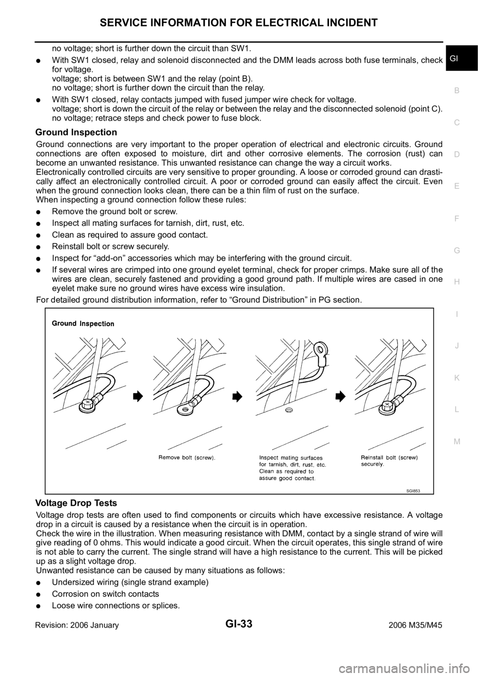
When inspecting a ground connection follow these rules:
Remove the ground bolt or screw.
Inspect all mating surfaces for tarnish, dirt, rust, etc.
Clean as required to assure good contact.
Reinstall bolt or screw securely.
Inspect for “add-on” accessories which may be interfering with the ground circuit.
If several wires are crimped into one ground eyelet terminal, check for proper crimps. Make sure all of the
wires are clean, securely fastened and providing a good ground path. If multiple wires are cased in one
eyelet make sure no ground wires have excess wire insulation.
For detailed ground distribution information, refer to “Ground Distribution” in PG section.
Voltage Drop Tests
Voltage drop tests are often used to find components or circuits which have excessive resistance. A voltage
drop in a circuit is caused by a resistance when the circuit is in operation.
Check the wire in the illustration. When measuring resistance with DMM, contact by a single strand of wire will
give reading of 0 ohms. This would indicate a good circuit. When the circuit operates, this single strand of wire
is not able to carry the current. The single strand will have a high resistance to the current. This will be picked
up as a slight voltage drop.
Unwanted resistance can be caused by many situations as follows:
Undersized wiring (single strand example)
Corrosion on switch contacts
Loose wire connections or splices.
SGI853
Page 3532 of 5621

POWER WINDOW SYSTEM
GW-13
C
D
E
F
G
H
J
K
L
MA
B
GW
Revision: 2006 January2006 M35/M45
POWER WINDOW SYSTEMPFP:25401
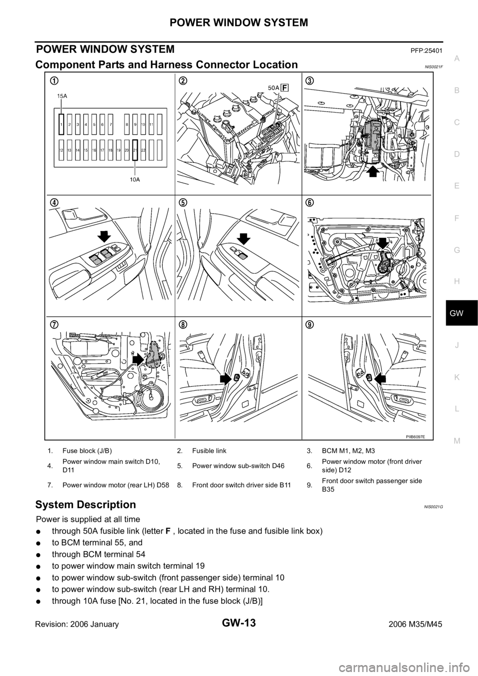
Component Parts and Harness Connector LocationNIS0021F
System DescriptionNIS0021G
Power is supplied at all time
through 50A fusible link (letter F , located in the fuse and fusible link box)
to BCM terminal 55, and
through BCM terminal 54
to power window main switch terminal 19
to power window sub-switch (front passenger side) terminal 10
to power window sub-switch (rear LH and RH) terminal 10.
through 10A fuse [No. 21, located in the fuse block (J/B)]
PIIB6097E
1. Fuse block (J/B) 2. Fusible link 3. BCM M1, M2, M3
4.Power window main switch D10,
D115. Power window sub-switch D46 6.Power window motor (front driver
side) D12
7. Power window motor (rear LH) D58 8. Front door switch driver side B11 9.Front door switch passenger side
B35
Page 3533 of 5621

GW-14
POWER WINDOW SYSTEM
Revision: 2006 January2006 M35/M45
to BCM terminal 42.
With ignition switch in ON or START position,
Power is supplied
through 15A fuse [No. 1, located in the fuse block (J/B)]
to BCM terminal 38, and
through BCM terminal 53
to power window main switch terminal 10
Ground supplied
to BCM terminal 52
through body grounds M16 and M70.
to power window main switch terminal 17
through body grounds M16 and M70.
to power window sub-switch (front passenger side) terminal 11
through body grounds M16 and M70.
to power window sub-switch (rear LH and RH) terminal 11
through body grounds B5, B40 and B131.
MANUAL OPERATION
Front Driver Side Door
WINDOW UP
When the front LH switch in the power window main switch is pressed in the up position,
Power is supplied
through power window main switch terminal 8
to power window motor (front driver side) terminal 2.
Ground is supplied
to power window motor (front driver side) terminal 1
through power window main switch terminal 11.
Then, the motor raises the window until the switch is released.
WINDOW DOWN
When the front LH switch in the power window main switch is pressed in the down position
Power is supplied
through power window main switch terminal 11
to power window motor (front driver side) terminal 1.
Ground is supplied
to power window motor (front driver side) terminal 2
through power window main switch terminal 8.
Then, the motor lowers the window until the switch is released.
Page 3536 of 5621

POWER WINDOW SYSTEM
GW-17
C
D
E
F
G
H
J
K
L
MA
B
GW
Revision: 2006 January2006 M35/M45
ANTI-PINCH SYSTEM
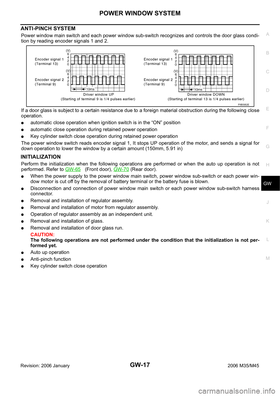
Power window main switch and each power window sub-switch recognizes and controls the door glass condi-
tion by reading encoder signals 1 and 2.
If a door glass is subject to a certain resistance due to a foreign material obstruction during the following close
operation.
automatic close operation when ignition switch is in the “ON” position
automatic close operation during retained power operation
Key cylinder switch close operation during retained power operation
The power window switch reads encoder signal 1, It stops UP operation of the motor, and sends a signal for
down operation to lower the window by a certain amount (150mm, 5.91 in)
INITIALIZATION
Perform the initialization when the following operations are performed or when the auto up operation is not
performed. Refer to GW-65
(Front door), GW-70 (Rear door).
When the power supply to the power window main switch, power window sub-switch or each power win-
dow motor is cut off by the removal of battery terminal or the battery fuse is blown.
Disconnection and connection of power window main switch or each power window sub-switch harness
connector.
Removal and installation of regulator assembly.
Removal and installation of motor from regulator assembly.
Operation of regulator assembly as an independent unit.
Removal and installation of glass.
Removal and installation of door glass run.
CAUTION:
The following operations are not performed under the condition that the initialization is not per-
formed yet.
Auto up operation
Anti-pinch function
Key cylinder switch close operation
PIIB5952E
Page 3546 of 5621
![INFINITI M35 2006 Factory Service Manual POWER WINDOW SYSTEM
GW-27
C
D
E
F
G
H
J
K
L
MA
B
GW
Revision: 2006 January2006 M35/M45
Terminal and Reference Value for BCMNIS0021L
Terminal Wire color Item ConditionVoltage [V]
(Approx.)
12 PFront do INFINITI M35 2006 Factory Service Manual POWER WINDOW SYSTEM
GW-27
C
D
E
F
G
H
J
K
L
MA
B
GW
Revision: 2006 January2006 M35/M45
Terminal and Reference Value for BCMNIS0021L
Terminal Wire color Item ConditionVoltage [V]
(Approx.)
12 PFront do](/manual-img/42/57023/w960_57023-3545.png)
POWER WINDOW SYSTEM
GW-27
C
D
E
F
G
H
J
K
L
MA
B
GW
Revision: 2006 January2006 M35/M45
Terminal and Reference Value for BCMNIS0021L
Terminal Wire color Item ConditionVoltage [V]
(Approx.)
12 PFront door switch
passenger side signalON (Open) 0
OFF (Close) Battery voltage
22 G Power window serial link IGN SW ON or power window
timer operating.
38 W Ignition switch (ON or START) Ignition switch
(ON or START position)Battery voltage
39 L CAN - H — —
40 P CAN - L — —
42 P Power source (Fuse) — Battery voltage
52 B Ground — 0
53 BR Rap signalIGN SW ON Battery voltage
Within 45 second after ignition
switch is turned to OFFBattery voltage
When driver side or passenger
side door is opened daring
retained power operation0
54 O Power window power supply — Battery voltage
55 W Power source (Fusible link) — Battery voltage
62 VFront door switch
driver side signalON (Open) 0
OFF (Close) Battery voltage
PIIA2344J
Page 3553 of 5621
![INFINITI M35 2006 Factory Service Manual GW-34
POWER WINDOW SYSTEM
Revision: 2006 January2006 M35/M45
BCM Power Supply and Ground Circuit CheckNIS0021R
1. CHECK FUSE
Check 15A fuse [No. 1, located in fuse block (J/B)]
Check 10A fuse [No. 21, INFINITI M35 2006 Factory Service Manual GW-34
POWER WINDOW SYSTEM
Revision: 2006 January2006 M35/M45
BCM Power Supply and Ground Circuit CheckNIS0021R
1. CHECK FUSE
Check 15A fuse [No. 1, located in fuse block (J/B)]
Check 10A fuse [No. 21,](/manual-img/42/57023/w960_57023-3552.png)
GW-34
POWER WINDOW SYSTEM
Revision: 2006 January2006 M35/M45
BCM Power Supply and Ground Circuit CheckNIS0021R
1. CHECK FUSE
Check 15A fuse [No. 1, located in fuse block (J/B)]
Check 10A fuse [No. 21, located in fuse block (J/B)]
Check 50A fusible link (letter F , located in the fuse and fusible link box).
NOTE:
Refer to GW-13, "
Component Parts and Harness Connector Location" .
OK or NG
OK >> GO TO 2.
NG >> If fuse is blown out, be sure to eliminate cause of malfunction before installing new fuse. Refer to
PG-3, "
POWER SUPPLY ROUTING CIRCUIT" .
2. CHECK POWER SUPPLY CIRCUIT
Check voltage between BCM connector and ground.
OK or NG
OK >> GO TO 3.
NG >> Check BCM power supply circuit for open or short.
3. CHECK GROUND CIRCUIT
1. Turn ignition switch OFF.
2. Disconnect BCM connector.
3. Check continuity between BCM connector and ground.
OK or NG
OK >> Power supply and ground circuit are OK.
NG >> Check BCM ground circuit for open or short.
Te r m i n a l s
Condition of
ignition switchVoltage (V)
(Approx.) (+)
(–)
BCM connector Terminal
M1 38
GroundON
Battery voltage
M242
OFF
55
PIIB5934E
BCM connector Terminal
GroundContinuity
M2 52 Yes
PIIB5935E
Page 3584 of 5621

FRONT DOOR GLASS AND REGULATOR
GW-65
C
D
E
F
G
H
J
K
L
MA
B
GW
Revision: 2006 January2006 M35/M45
Inspection after Removal
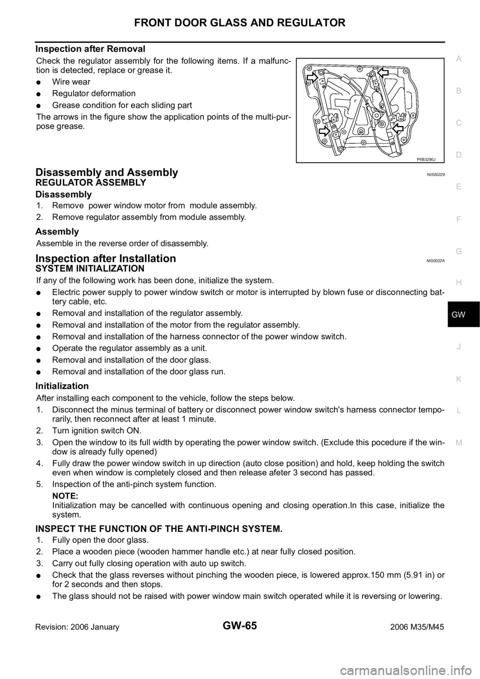
Check the regulator assembly for the following items. If a malfunc-
tion is detected, replace or grease it.
Wire wear
Regulator deformation
Grease condition for each sliding part
The arrows in the figure show the application points of the multi-pur-
pose grease.
Disassembly and AssemblyNIS00229
REGULATOR ASSEMBLY
Disassembly
1. Remove power window motor from module assembly.
2. Remove regulator assembly from module assembly.
Assembly
Assemble in the reverse order of disassembly.
Inspection after InstallationNIS0022A
SYSTEM INITIALIZATION
If any of the following work has been done, initialize the system.
Electric power supply to power window switch or motor is interrupted by blown fuse or disconnecting bat-
tery cable, etc.
Removal and installation of the regulator assembly.
Removal and installation of the motor from the regulator assembly.
Removal and installation of the harness connector of the power window switch.
Operate the regulator assembly as a unit.
Removal and installation of the door glass.
Removal and installation of the door glass run.
Initialization
After installing each component to the vehicle, follow the steps below.
1. Disconnect the minus terminal of battery or disconnect power window switch's harness connector tempo-
rarily, then reconnect after at least 1 minute.
2. Turn ignition switch ON.
3. Open the window to its full width by operating the power window switch. (Exclude this pocedure if the win-
dow is already fully opened)
4. Fully draw the power window switch in up direction (auto close position) and hold, keep holding the switch
even when window is completely closed and then release afeter 3 second has passed.
5. Inspection of the anti-pinch system function.
NOTE:
Initialization may be cancelled with continuous opening and closing operation.In this case, initialize the
system.
INSPECT THE FUNCTION OF THE ANTI-PINCH SYSTEM.
1. Fully open the door glass.
2. Place a wooden piece (wooden hammer handle etc.) at near fully closed position.
3. Carry out fully closing operation with auto up switch.
Check that the glass reverses without pinching the wooden piece, is lowered approx.150 mm (5.91 in) or
for 2 seconds and then stops.
The glass should not be raised with power window main switch operated while it is reversing or lowering.
PIIB3290J
Page 3589 of 5621

GW-70
REAR DOOR GLASS AND REGULATOR
Revision: 2006 January2006 M35/M45
Disassembly and AssemblyNIS0022C
REGULATOR ASSEMBLY
Disassembly
Remove power window motor from regulator assembly.
Assembly
Assemble in the reverse order of disassembly.
Inspection after InstallationNIS0022D
SYSTEM INITIALIZATION
If any of the following work has been done, initialize the system.
Electric power sauce to power window switch or motor is interrupted by broken fuse or disconnecting bat-
tery cable, etc.
Removal and installation of the regulator assembly.
Removal and installation of the motor from the regulator assembly.
Removal and installation of the harness connector of the power window switch.
Operate the regulator assembly as a unit.
Removal and installation of the door glass.
Removal and installation of the door glass run.
Initialization
After installing each component to the vehicle, follow the steps below.
1. Disconnect the minus terminal of battery or disconnect power window switch's harness connector tempo-
rarily, then reconnect after at least 1 minute.
2. Turn ignition switch ON.
3. Open the window to its full width by operating the power window switch. (Exclude this pocedure if the win-
dow is already fully opened)
4. Fully draw the power window switch in up direction (auto close position) and hold, keep holding the switch
even when window is completely closed and then release afeter 3 second has passed.
5. Inspection of the anti-pinch system function.
NOTE:
Initialization may be cancelled with continuous opening and closing operation.In this case, initialize the
system.
INSPECT THE FUNCTION OF THE ANTI-PINCH SYSTEM
1. Fully open the door glass.
2. Place a wooden piece (wooden hammer handle etc.) at near fully closed position.
3. Carry out fully closing operation with auto up switch.
Check that the glass reverses without pinching the wooden piece, is lowered approx.150mm (5.91in) or
for 2 seconds and then stops.
The glass should not be raised with power window main switch operated while it is reversing or lowering.
CAUTION:
Do not inspect with pinching a part of worker's body, a hand etc. Work carefully not to be pinched.
Check that auto up function is normal before inspection following the system initialization.
FITTING INSPECTION
Make sure the glass is securely fit into the glass run groove.
Lower the glass slightly [approx. 10 to 20 mm (0.39 to 0.79 in)], and make sure the clearance to the sash
is parallel. If the clearance between the glass and sash is not parallel, loosen the regulator mounting bolts,
guide rail mounting bolts, and glass and carrier plate mounting bolts to correct the glass position.