2006 INFINITI M35 ABS
[x] Cancel search: ABSPage 3419 of 5621

FL-6
FUEL LEVEL SENSOR UNIT, FUEL FILTER AND FUEL PUMP ASSEMBLY
Revision: 2006 January2006 M35/M45
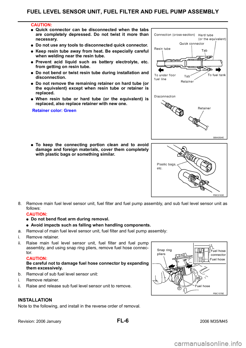
CAUTION:
Quick connector can be disconnected when the tabs
are completely depressed. Do not twist it more than
necessary.
Do not use any tools to disconnected quick connector.
Keep resin tube away from heat. Be especially careful
when welding near the resin tube.
Prevent acid liquid such as battery electrolyte, etc.
from getting on resin tube.
Do not bend or twist resin tube during installation and
disconnection.
Do not remove the remaining retainer on hard tube (or
the equivalent) except when resin tube or retainer is
replaced.
When resin tube or hard tube (or the equivalent) is
replaced, also replace retainer with new one.
To keep the connecting portion clean and to avoid
damage and foreign materials, cover them completely
with plastic bags or something similar.
8. Remove main fuel level sensor unit, fuel filter and fuel pump assembly, and sub fuel level sensor unit as
follows:
CAUTION:
Do not bend float arm during removal.
Avoid impacts such as falling when handling components.
a. Removal of main fuel level sensor unit, fuel filter and fuel pump assembly:
i. Remove retainer.
ii. Raise main fuel level sensor unit, fuel filter and fuel pump
assembly, and using snap ring pliers, remove fuel hose connec-
tor.
CAUTION:
Be careful not to damage fuel hose connector by expanding
them excessively.
b. Removal of sub fuel level sensor unit:
i. Remove retainer.
ii. Raise and release sub fuel level sensor unit to remove.
INSTALLATION
Note to the following, and install in the reverse order of removal. Retainer color: Green
SBIA0504E
PBIC0163E
PBIC1578E
Page 3420 of 5621

FUEL LEVEL SENSOR UNIT, FUEL FILTER AND FUEL PUMP ASSEMBLY
FL-7
C
D
E
F
G
H
I
J
K
L
MA
FL
Revision: 2006 January2006 M35/M45
Fuel hose
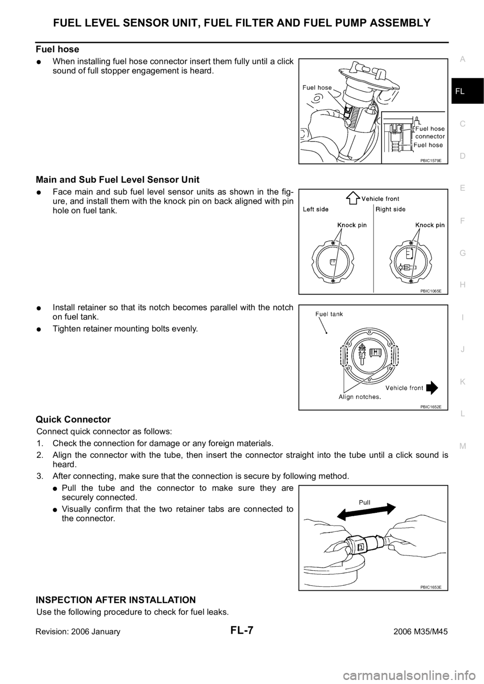
When installing fuel hose connector insert them fully until a click
sound of full stopper engagement is heard.
Main and Sub Fuel Level Sensor Unit
Face main and sub fuel level sensor units as shown in the fig-
ure, and install them with the knock pin on back aligned with pin
hole on fuel tank.
Install retainer so that its notch becomes parallel with the notch
on fuel tank.
Tighten retainer mounting bolts evenly.
Quick Connector
Connect quick connector as follows:
1. Check the connection for damage or any foreign materials.
2. Align the connector with the tube, then insert the connector straight into the tube until a click sound is
heard.
3. After connecting, make sure that the connection is secure by following method.
Pull the tube and the connector to make sure they are
securely connected.
Visually confirm that the two retainer tabs are connected to
the connector.
INSPECTION AFTER INSTALLATION
Use the following procedure to check for fuel leaks.
PBIC1579E
PBIC1065E
PBIC1652E
PBIC1653E
Page 3421 of 5621

FL-8
FUEL LEVEL SENSOR UNIT, FUEL FILTER AND FUEL PUMP ASSEMBLY
Revision: 2006 January2006 M35/M45
1. Turn ignition switch “ON” (with engine stopped), then check connections for leaks by applying fuel pres-
sure to fuel piping.
2. Start engine and let it idle and make sure there are no fuel leaks at the fuel system connections.
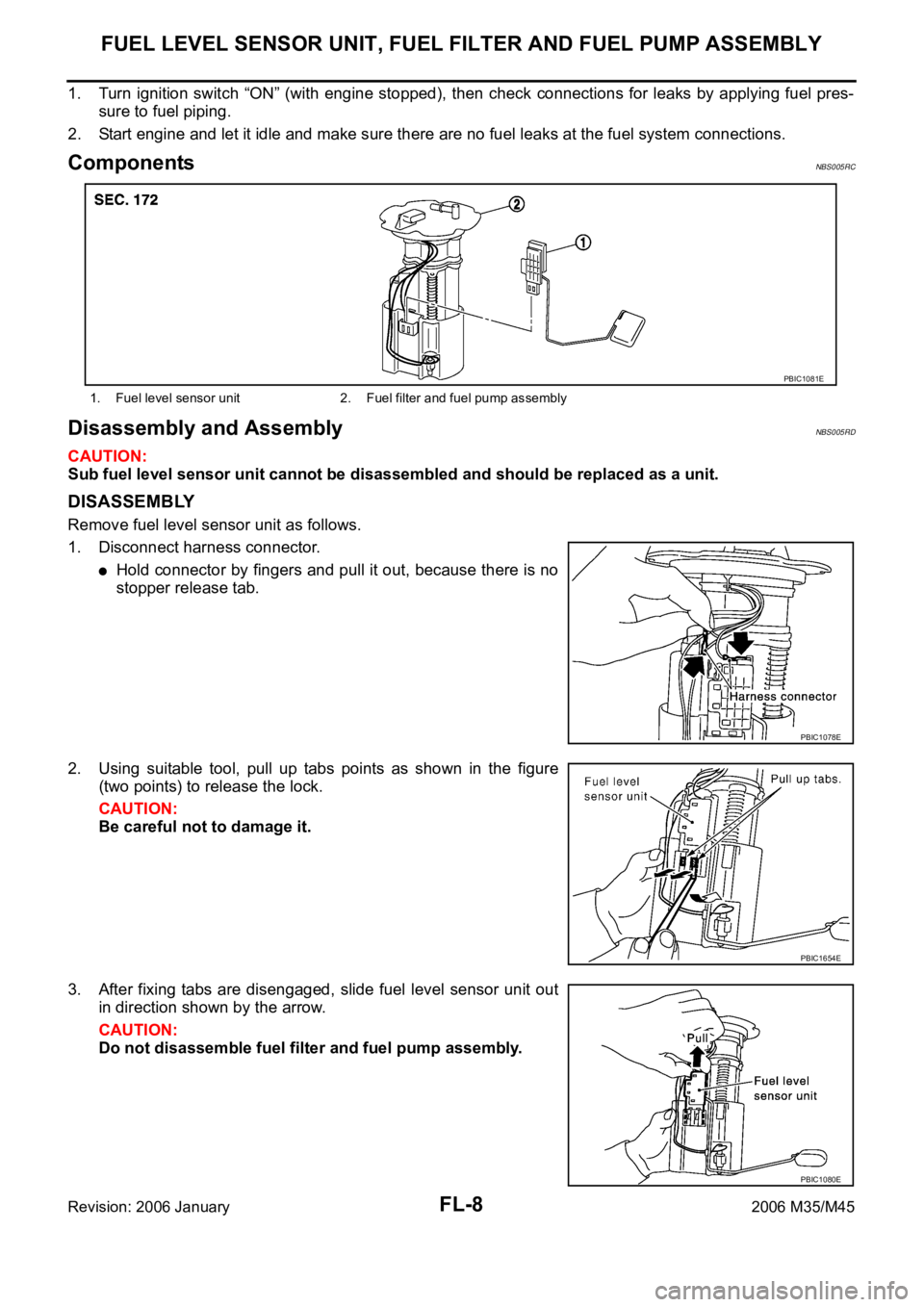
ComponentsNBS005RC
Disassembly and AssemblyNBS005RD
CAUTION:
Sub fuel level sensor unit cannot be disassembled and should be replaced as a unit.
DISASSEMBLY
Remove fuel level sensor unit as follows.
1. Disconnect harness connector.
Hold connector by fingers and pull it out, because there is no
stopper release tab.
2. Using suitable tool, pull up tabs points as shown in the figure
(two points) to release the lock.
CAUTION:
Be careful not to damage it.
3. After fixing tabs are disengaged, slide fuel level sensor unit out
in direction shown by the arrow.
CAUTION:
Do not disassemble fuel filter and fuel pump assembly.
1. Fuel level sensor unit 2. Fuel filter and fuel pump assembly
PBIC1081E
PBIC1078E
PBIC1654E
PBIC1080E
Page 3428 of 5621

FSU-1
FRONT SUSPENSION
E SUSPENSION
CONTENTS
C
D
F
G
H
I
J
K
L
M
SECTION FSU
A
B
FSU
Revision: 2006 January2006 M35/M45
FRONT SUSPENSION
2WD
PRECAUTIONS .......................................................... 3
Caution ..................................................................... 3
PREPARATION ........................................................... 4
Special Service Tools [SST] ..................................... 4
Commercial Service Tools ........................................ 4
NOISE, VIBRATION AND HARSHNESS (NVH)
TROUBLESHOOTING ................................................ 5
NVH Troubleshooting Chart ..................................... 5
FRONT SUSPENSION ASSEMBLY ........................... 6
On-Vehicle Inspection and Service .......................... 6
INSPECTION OF LOWER BALL JOINT END
PLAY ..................................................................... 6
SHOCK ABSORBER INSPECTION ..................... 6
Wheel Alignment Inspection ..................................... 6
DESCRIPTION ...................................................... 6
PRELIMINARY CHECK ........................................ 6
GENERAL INFORMATION AND RECOMMEN-
DATIONS .............................................................. 6
THE ALIGNMENT PROCESS .............................. 7
INSPECTION OF CAMBER, CASTER AND
KINGPIN INCLINATION ANGLES ........................ 7
Components ............................................................. 8
Removal and Installation .......................................... 9
REMOVAL ........................................................
..... 9
INSTALLATION ................................................... 10
COIL SPRING AND SHOCK ABSORBER ................11
Removal and Installation ......................................... 11
REMOVAL ........................................................
.... 11
INSTALLATION .................................................... 11
Disassembly and Assembly .................................... 11
DISASSEMBLY .................................................... 11
INSPECTION AFTER DISASSEMBLY ............... 12
ASSEMBLY ......................................................... 12
TRANSVERSE LINK ................................................ 14
Removal and Installation ........................................ 14
REMOVAL ........................................................
... 14
INSPECTION AFTER REMOVAL ....................... 14
INSTALLATION ................................................... 15UPPER LINK ............................................................. 16
Removal and Installation ........................................ 16
REMOVAL ........................................................
... 16
INSPECTION AFTER REMOVAL ....................... 16
INSTALLATION ................................................... 16
STABILIZER BAR ..................................................... 18
Removal and Installation ........................................ 18
REMOVAL ........................................................
... 18
INSPECTION AFTER REMOVAL ....................... 18
INSTALLATION ................................................... 18
SERVICE DATA AND SPECIFICATIONS (SDS) ...... 19
Wheel Alignment (Unladen) .................................... 19
Ball Joint ....................................................
............. 19
Wheelarch Height (Unladen*) ................................. 19
AWD
PRECAUTIONS ........................................................ 20
Caution ................................................................... 20
PREPARATION ......................................................... 21
Special Service Tools [SST] ................................... 21
Commercial Service Tools ...................................... 21
NOISE, VIBRATION AND HARSHNESS (NVH)
TROUBLESHOOTING .............................................. 22
NVH Troubleshooting Chart ................................... 22
FRONT SUSPENSION ASSEMBLY ......................... 23
On-Vehicle Inspection and Service ......................... 23
INSPECTION OF LOWER BALL JOINT END
PLAY .................................................................... 23
SHOCK ABSORBER INSPECTION .................... 23
Wheel Alignment Inspection ................................... 23
DESCRIPTION .................................................... 23
PRELIMINARY CHECK ....................................... 23
GENERAL INFORMATION AND RECOMMEN-
DATIONS ............................................................. 23
THE ALIGNMENT PROCESS ............................. 24
INSPECTION OF CAMBER, CASTER AND
KINGPIN INCLINATION ANGLES ....................... 24
Page 3429 of 5621

FSU-2Revision: 2006 January2006 M35/M45 Components ........................................................... 25
Removal and Installation ........................................ 26
REMOVAL ........................................................
... 26
INSTALLATION .................................................... 26
COIL SPRING AND SHOCK ABSORBER ............... 28
Removal and Installation ........................................ 28
REMOVAL ........................................................
... 28
INSTALLATION .................................................... 28
Disassembly and Assembly .................................... 28
DISASSEMBLY ................................................... 28
INSPECTION AFTER DISASSEMBLY ................ 29
ASSEMBLY ......................................................... 29
TRANSVERSE LINK ................................................. 31
Removal and Installation ........................................ 31
REMOVAL ........................................................
... 31
INSPECTION AFTER REMOVAL ........................ 31
INSTALLATION .................................................... 32UPPER LINK ............................................................. 33
Removal and Installation ......................................... 33
REMOVAL ............................................................ 33
INSPECTION AFTER REMOVAL ........................ 33
INSTALLATION .................................................... 33
STABILIZER BAR ..................................................... 35
Removal and Installation ......................................... 35
REMOVAL ............................................................ 35
INSPECTION AFTER REMOVAL ........................ 35
INSTALLATION .................................................... 35
SERVICE DATA AND SPECIFICATIONS (SDS) ...... 36
Wheel Alignment (Unladen) .................................... 36
Ball Joint ................................................................. 36
Wheelarch Height (Unladen*) ................................. 36
Page 3431 of 5621
![INFINITI M35 2006 Factory Service Manual FSU-4
[2WD]
PREPARATION
Revision: 2006 January2006 M35/M45
PREPARATIONPFP:00002
Special Service Tools [SST]NES000I7
The actual shapes of Kent-Moore tools may differ from those of special service tools INFINITI M35 2006 Factory Service Manual FSU-4
[2WD]
PREPARATION
Revision: 2006 January2006 M35/M45
PREPARATIONPFP:00002
Special Service Tools [SST]NES000I7
The actual shapes of Kent-Moore tools may differ from those of special service tools](/manual-img/42/57023/w960_57023-3430.png)
FSU-4
[2WD]
PREPARATION
Revision: 2006 January2006 M35/M45
PREPARATIONPFP:00002
Special Service Tools [SST]NES000I7
The actual shapes of Kent-Moore tools may differ from those of special service tools illustrated here.
Commercial Service ToolsNES000I8
Tool number
(Kent-Moore No.)
Tool nameDescription
KV991040S0
(—)
CCK gauge attachment
1. Plate
2. Guide bolt
3. Nut
4. Spring
5. Center plate
6. KV99104020 Adapter A
a: 72 mm (2.83 in) dia.
7. KV99104030 Adapter B
b: 65 mm (2.56 in) dia.
8. KV99104040 Adapter C
c: 57 mm (2.24 in) dia.
9. KV99104050 Adapter D
d: 53.4 mm (2.102 in) dia.Measuring wheel alignment
ST35652000
(—)
Strut attachmentDisassembling and assembling shock
absorber
ST3127S000
(See J-25765-A)
Preload Gauge
1. GG91030000
(J-25765-A)
Torque wrench
2. HT62940000
(—)
Socket adapter
3. HT62900000
(—)
Socket adapterMeasuring rotating torque of ball joint
S-NT498
ZZA0807D
NT124
Tool nameDescription
Power tool
Removing wheel nuts
Removing torque member fixing bolts
Removing undercover
Removing front suspension compo-
nents parts
Removing hub lock nut
Spring compressor Removing and installing coil springPBIC0190E
S-NT717
Page 3433 of 5621
![INFINITI M35 2006 Factory Service Manual FSU-6
[2WD]
FRONT SUSPENSION ASSEMBLY
Revision: 2006 January2006 M35/M45
FRONT SUSPENSION ASSEMBLYPFP:54010
On-Vehicle Inspection and ServiceNES000IA
Make sure the mounting conditions (looseness, INFINITI M35 2006 Factory Service Manual FSU-6
[2WD]
FRONT SUSPENSION ASSEMBLY
Revision: 2006 January2006 M35/M45
FRONT SUSPENSION ASSEMBLYPFP:54010
On-Vehicle Inspection and ServiceNES000IA
Make sure the mounting conditions (looseness,](/manual-img/42/57023/w960_57023-3432.png)
FSU-6
[2WD]
FRONT SUSPENSION ASSEMBLY
Revision: 2006 January2006 M35/M45
FRONT SUSPENSION ASSEMBLYPFP:54010
On-Vehicle Inspection and ServiceNES000IA
Make sure the mounting conditions (looseness, back lash) of each component and component conditions
(wear, damage) are normal.
INSPECTION OF LOWER BALL JOINT END PLAY
1. Set front wheels in a straight-ahead position. Do not depress brake pedal.
2. Place an iron bar or similar tool between transverse link and steering knuckle.
3. Measure axial end play by prying it up and down.
CAUTION:
Be careful not to damage ball joint boot. Do not damage the installation position by applying
excessive force.
SHOCK ABSORBER INSPECTION
Check for oil leakage, damage and breakage of installation positions.
Wheel Alignment InspectionNES000IB
DESCRIPTION
Measure wheel alignment under unladen conditions.
NOTE:
“Unladen conditions” means that fuel, engine coolant, and lubricant are full. Spare tire, jack, hand tools and
mats are in designated positions.
PRELIMINARY CHECK
Check the following:
1. Tires for improper air pressure and wear.
2. Road wheels for runout. Refer to WT-6, "
ROAD WHEEL" .
3. Wheel bearing axial end play. Refer to FAX-5, "
WHEEL BEARING INSPECTION" .
4. Transverse link ball joint axial end play. Refer to FSU-14, "
INSPECTION AFTER REMOVAL" .
5. Shock absorber operation.
6. Each mounting part of axle and suspension for looseness and deformation.
7. Each of suspension member, shock absorber, upper link and transverse link for cracks, deformation and
other damage.
8. Vehicle height (posture).
GENERAL INFORMATION AND RECOMMENDATIONS
A four-wheel thrust alignment should be performed.
–This type of alignment is recommended for any NISSAN/INFINITI vehicle.
–The four-wheel “thrust” process helps ensure that the vehicle is properly aligned and the steering wheel is
centered.
–The alignment rack itself should be capable of accepting any NISSAN/INFINITI vehicle.
–The rack should be checked to ensure that it is level.
Make sure the machine is properly calibrated.
–Your alignment equipment should be regularly calibrated in order to give correct information.
–Check with the manufacturer of your specific equipment for their recommended Service/Calibration
Schedule.Axial end play : 0 mm (0 in)
Page 3436 of 5621
![INFINITI M35 2006 Factory Service Manual FRONT SUSPENSION ASSEMBLY
FSU-9
[2WD]
C
D
F
G
H
I
J
K
L
MA
B
FSU
Revision: 2006 January2006 M35/M45
Refer to GI section for symbol marks in the figure. Refer to GI-9, "HOW TO USE THIS MANUAL" INFINITI M35 2006 Factory Service Manual FRONT SUSPENSION ASSEMBLY
FSU-9
[2WD]
C
D
F
G
H
I
J
K
L
MA
B
FSU
Revision: 2006 January2006 M35/M45
Refer to GI section for symbol marks in the figure. Refer to GI-9, "HOW TO USE THIS MANUAL"](/manual-img/42/57023/w960_57023-3435.png)
FRONT SUSPENSION ASSEMBLY
FSU-9
[2WD]
C
D
F
G
H
I
J
K
L
MA
B
FSU
Revision: 2006 January2006 M35/M45
Refer to GI section for symbol marks in the figure. Refer to GI-9, "HOW TO USE THIS MANUAL" .
Removal and Installation NES000ID
REMOVAL
1. For VK45DE engine models, disconnect related electric wires and hoses from engine assembly to remove
front suspension member with engine assembly. Refer to EM-244, "
ENGINE ASSEMBLY" .
2. Remove cowl top panel and hood. Refer to EI-18, "
COWL TOP" , EI-17, "HOOD" .
3. For VQ35DE engine models, install engine slinger, and then hoist engine. Refer to EM-113, "
Removal and
Installation (2WD Models)" .
4. Remove tires from vehicle with a power tool.
5. Remove wheel sensor from steering knuckle. Refer to BRC-57, "
WHEEL SENSOR" .
CAUTION:
Do not pull on wheel sensor harness.
6. Remove brake hose bracket. Refer to BR-12, "
BRAKE TUBE AND HOSE" .
7. Remove undercover with a power tool.
8. Remove cotter pin (1), and then loosen the nut.
9. Remove steering outer socket (2) from steering knuckle (3) so
as not to damage ball joint boot (4) using the ball joint remover
(suitable tool).
CAUTION:
Temporarily tighten the nut to prevent damage to threads
and to prevent the ball joint remover (suitable tool) from
suddenly coming off.
10. Remove the mounting nut on the upper side of stabilizer con-
necting rod with a power tool, and then remove stabilizer con-
necting rod from transverse link.
11. Separate steering gear assembly and lower joint. Refer to PS-13, "
STEERING COLUMN" .
12. Remove rack stay. Refer to FSU-8, "
Components" .
13. Remove steering hydraulic piping bracket from front suspension member. Refer to PS-38, "
HYDRAULIC
LINE" .
14. Remove the mounting nut and bolt on the lower side of shock absorber with a power tool, and then
remove shock absorber from transverse link.
15. Remove cotter pin of transverse link and steering knuckle, and then loosen nut.
16. Set jack under front suspension member.
17. Remove transverse link from steering knuckle so as not to damage ball joint boot using the ball joint
remover (suitable tool)
CAUTION:
Temporarily tighten the nut to prevent damage to threads and to prevent ball joint remover (suit-
able tool) from suddenly coming off.
18. Remove the mounting nuts of engine mounting insulator. Refer to EM-113, "
ENGINE ASSEMBLY" .
19. Remove the mounting bolts of member bracket, and then remove member bracket from front suspension
member with a power tool. Refer to FSU-8, "
Components" .
20. Remove the mounting nut and bolts of member stay, and then remove member stay from front suspension
member and vehicle with a power tool.
21. Remove the mounting nut of front suspension member with a power tool. Refer to FSU-8, "
Components" .
22. For VQ35DE engine models, gradually lower a jack to remove front suspension assembly from vehicle.
1. Shock absorber mounting bracket 2. Bound bumper 3. Rubber seat
4. Coil spring 5. Shock absorber 6. Upper link
7. Steering knuckle 8. Transverse link 9. Washer
10. Steering stopper bracket 11. Stabilizer connecting rod 12. Stabilizer bar
13. Stabilizer bushing 14. Stabilizer clamp 15. Front suspension member
16. Rack stay 17. Member stay 18. Member bracket
19. Clamp 20. Cotter pin 21. Stopper rubber
SGIA1183E