2006 INFINITI M35 service schedule
[x] Cancel search: service schedulePage 2393 of 5621
![INFINITI M35 2006 Factory Service Manual EC-850
[VK45DE]
TROUBLE DIAGNOSIS
Revision: 2006 January2006 M35/M45
*: This function is not necessary in the usual service procedure.
SELF-DIAG RESULTS MODE
Self Diagnostic Item
Regarding items of DT INFINITI M35 2006 Factory Service Manual EC-850
[VK45DE]
TROUBLE DIAGNOSIS
Revision: 2006 January2006 M35/M45
*: This function is not necessary in the usual service procedure.
SELF-DIAG RESULTS MODE
Self Diagnostic Item
Regarding items of DT](/manual-img/42/57023/w960_57023-2392.png)
EC-850
[VK45DE]
TROUBLE DIAGNOSIS
Revision: 2006 January2006 M35/M45
*: This function is not necessary in the usual service procedure.
SELF-DIAG RESULTS MODE
Self Diagnostic Item
Regarding items of DTC and 1st trip DTC, refer to EC-765, "Emission-Related Diagnostic Information" .
Freeze Frame Data and 1st Trip Freeze Frame Data
EVAP SYSTEM CLOSE CLOSE THE EVAP CANISTER VENT CONTROL VALVE IN
ORDER TO MAKE EVAP SYSTEM CLOSE UNDER THE
FOLLOWING CONDITIONS.
IGN SW ON
ENGINE NOT RUNNING
AMBIENT TEMPERATURE IS ABOVE 0C (32F).
NO VACUUM AND NO HIGH PRESSURE IN EVAP SYS-
TEM
FUEL TANK TEMP. IS MORE THAN 0C (32F).
WITHIN 10 MINUTES AFTER STARTING “EVAP SYS-
TEM CLOSE”
WHEN TRYING TO EXECUTE “EVAP SYSTEM CLOSE”
UNDER THE CONDITION EXCEPT ABOVE, CONSULT-
II WILL DISCONTINUE IT AND DISPLAY APPROPRI-
ATE INSTRUCTION.
NOTE:
WHEN STARTING ENGINE, CONSULT-II MAY DISPLAY
“BATTERY VOLTAGE IS LOW. CHARGE BATTERY”,
EVEN IN USING CHARGED BATTERY.When detecting EVAP vapor leak
point of EVAP system
VIN REGISTRATION
IN THIS MODE VIN IS REGISTERED IN ECM When registering VIN in ECM
TARGET IDLE RPM ADJ*
IDLE CONDITION When setting target idle speed
TARGET IGN TIM ADJ*
IDLE CONDITION When adjusting target ignition tim-
ing WORK ITEM CONDITION USAGE
Freeze frame data
item*Description
DIAG TROUBLE
CODE
[PXXXX]
The engine control component part/control system has a trouble code, it is displayed as PXXXX. (Refer to
EC-726, "
INDEX FOR DTC" .)
FUEL SYS-B1
“Fuel injection system status” at the moment a malfunction is detected is displayed.
One mode in the following is displayed.
Mode2: Open loop due to detected system malfunction
Mode3: Open loop due to driving conditions (power enrichment, deceleration enleanment)
Mode4: Closed loop - using oxygen sensor(s) as feedback for fuel control
Mode5: Open loop - has not yet satisfied condition to go to closed loop FUEL SYS-B2
CAL/LD VALUE [%]
The calculated load value at the moment a malfunction is detected is displayed.
COOLANT TEMP [
C]
or [
F]The engine coolant temperature at the moment a malfunction is detected is displayed.
L-FUEL TRM-B1 [%]
“Long-term fuel trim” at the moment a malfunction is detected is displayed.
The long-term fuel trim indicates much more gradual feedback compensation to the base fuel schedule
than short-term fuel trim. L-FUEL TRM-B2 [%]
S-FUEL TRM-B1 [%]
“Short-term fuel trim” at the moment a malfunction is detected is displayed.
The short-term fuel trim indicates dynamic or instantaneous feedback compensation to the base fuel
schedule. S-FUEL TRM-B2 [%]
ENGINE SPEED
[rpm]
The engine speed at the moment a malfunction is detected is displayed.
VEHICL SPEED
[km/h] or [mph]
The vehicle speed at the moment a malfunction is detected is displayed.
Page 3433 of 5621
![INFINITI M35 2006 Factory Service Manual FSU-6
[2WD]
FRONT SUSPENSION ASSEMBLY
Revision: 2006 January2006 M35/M45
FRONT SUSPENSION ASSEMBLYPFP:54010
On-Vehicle Inspection and ServiceNES000IA
Make sure the mounting conditions (looseness, INFINITI M35 2006 Factory Service Manual FSU-6
[2WD]
FRONT SUSPENSION ASSEMBLY
Revision: 2006 January2006 M35/M45
FRONT SUSPENSION ASSEMBLYPFP:54010
On-Vehicle Inspection and ServiceNES000IA
Make sure the mounting conditions (looseness,](/manual-img/42/57023/w960_57023-3432.png)
FSU-6
[2WD]
FRONT SUSPENSION ASSEMBLY
Revision: 2006 January2006 M35/M45
FRONT SUSPENSION ASSEMBLYPFP:54010
On-Vehicle Inspection and ServiceNES000IA
Make sure the mounting conditions (looseness, back lash) of each component and component conditions
(wear, damage) are normal.
INSPECTION OF LOWER BALL JOINT END PLAY
1. Set front wheels in a straight-ahead position. Do not depress brake pedal.
2. Place an iron bar or similar tool between transverse link and steering knuckle.
3. Measure axial end play by prying it up and down.
CAUTION:
Be careful not to damage ball joint boot. Do not damage the installation position by applying
excessive force.
SHOCK ABSORBER INSPECTION
Check for oil leakage, damage and breakage of installation positions.
Wheel Alignment InspectionNES000IB
DESCRIPTION
Measure wheel alignment under unladen conditions.
NOTE:
“Unladen conditions” means that fuel, engine coolant, and lubricant are full. Spare tire, jack, hand tools and
mats are in designated positions.
PRELIMINARY CHECK
Check the following:
1. Tires for improper air pressure and wear.
2. Road wheels for runout. Refer to WT-6, "
ROAD WHEEL" .
3. Wheel bearing axial end play. Refer to FAX-5, "
WHEEL BEARING INSPECTION" .
4. Transverse link ball joint axial end play. Refer to FSU-14, "
INSPECTION AFTER REMOVAL" .
5. Shock absorber operation.
6. Each mounting part of axle and suspension for looseness and deformation.
7. Each of suspension member, shock absorber, upper link and transverse link for cracks, deformation and
other damage.
8. Vehicle height (posture).
GENERAL INFORMATION AND RECOMMENDATIONS
A four-wheel thrust alignment should be performed.
–This type of alignment is recommended for any NISSAN/INFINITI vehicle.
–The four-wheel “thrust” process helps ensure that the vehicle is properly aligned and the steering wheel is
centered.
–The alignment rack itself should be capable of accepting any NISSAN/INFINITI vehicle.
–The rack should be checked to ensure that it is level.
Make sure the machine is properly calibrated.
–Your alignment equipment should be regularly calibrated in order to give correct information.
–Check with the manufacturer of your specific equipment for their recommended Service/Calibration
Schedule.Axial end play : 0 mm (0 in)
Page 3450 of 5621
![INFINITI M35 2006 Factory Service Manual FRONT SUSPENSION ASSEMBLY
FSU-23
[AWD]
C
D
F
G
H
I
J
K
L
MA
B
FSU
Revision: 2006 January2006 M35/M45
FRONT SUSPENSION ASSEMBLYPFP:54010
On-Vehicle Inspection and ServiceNES000IQ
Make sure the mount INFINITI M35 2006 Factory Service Manual FRONT SUSPENSION ASSEMBLY
FSU-23
[AWD]
C
D
F
G
H
I
J
K
L
MA
B
FSU
Revision: 2006 January2006 M35/M45
FRONT SUSPENSION ASSEMBLYPFP:54010
On-Vehicle Inspection and ServiceNES000IQ
Make sure the mount](/manual-img/42/57023/w960_57023-3449.png)
FRONT SUSPENSION ASSEMBLY
FSU-23
[AWD]
C
D
F
G
H
I
J
K
L
MA
B
FSU
Revision: 2006 January2006 M35/M45
FRONT SUSPENSION ASSEMBLYPFP:54010
On-Vehicle Inspection and ServiceNES000IQ
Make sure the mounting conditions (looseness, back lash) of each component and component conditions
(wear, damage) are normal.
INSPECTION OF LOWER BALL JOINT END PLAY
1. Set front wheels in a straight-ahead position. Do not depress brake pedal.
2. Place an iron bar or similar tool between transverse link and steering knuckle.
3. Measure axial end play by prying it up and down.
CAUTION:
Be careful not to damage ball joint boot. Do not damage the installation position by applying
excessive force.
SHOCK ABSORBER INSPECTION
Check for oil leakage, damage and breakage of installation positions.
Wheel Alignment InspectionNES000IR
DESCRIPTION
Measure wheel alignment under unladen conditions.
NOTE:
“Unladen conditions” means that fuel, engine coolant, and lubricant are full. Spare tire, jack, hand tools and
mats are in designated positions.
PRELIMINARY CHECK
Check the following:
1. Tires for improper air pressure and wear.
2. Road wheels for runout. Refer to WT-6, "
ROAD WHEEL" .
3. Wheel bearing axial end play. Refer to FAX-5, "
WHEEL BEARING INSPECTION" .
4. Transverse link ball joint axial end play. Refer to FSU-31, "
INSPECTION AFTER REMOVAL" .
5. Shock absorber operation.
6. Each mounting part of axle and suspension for looseness and deformation.
7. Each of suspension member, shock absorber, upper link and transverse link for cracks, deformation and
other damage.
8. Vehicle height (posture).
GENERAL INFORMATION AND RECOMMENDATIONS
A four-wheel thrust alignment should be performed.
–This type of alignment is recommended for any NISSAN/INFINITI vehicle.
–The four-wheel “thrust” process helps ensure that the vehicle is properly aligned and the steering wheel is
centered.
–The alignment rack itself should be capable of accepting any NISSAN/INFINITI vehicle.
–The rack should be checked to ensure that it is level.
Make sure the machine is properly calibrated.
–Your alignment equipment should be regularly calibrated in order to give correct information.
–Check with the manufacturer of your specific equipment for their recommended Service/Calibration
Schedule.Axial end play : 0 mm (0 in)
Page 4778 of 5621

MA-1
MAINTENANCE
L MAINTENANCE
CONTENTS
C
D
E
F
G
H
I
J
K
M
SECTION MA
A
B
MA
Revision: 2006 January2006 M35/M45
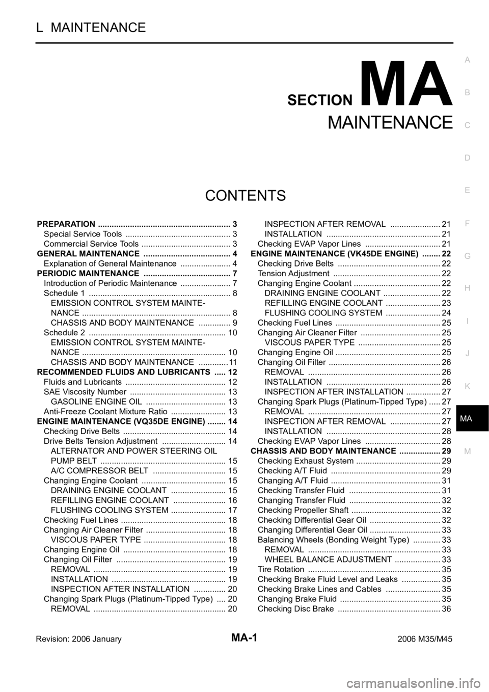
MAINTENANCE
PREPARATION ........................................................... 3
Special Service Tools ............................................... 3
Commercial Service Tools ........................................ 3
GENERAL MAINTENANCE ....................................... 4
Explanation of General Maintenance ....................... 4
PERIODIC MAINTENANCE ....................................... 7
Introduction of Periodic Maintenance ....................... 7
Schedule 1 ............................................................... 8
EMISSION CONTROL SYSTEM MAINTE-
NANCE .................................................................. 8
CHASSIS AND BODY MAINTENANCE ............... 9
Schedule 2 ............................................................. 10
EMISSION CONTROL SYSTEM MAINTE-
NANCE ................................................................ 10
CHASSIS AND BODY MAINTENANCE .............. 11
RECOMMENDED FLUIDS AND LUBRICANTS ...... 12
Fluids and Lubricants ............................................. 12
SAE Viscosity Number ........................................... 13
GASOLINE ENGINE OIL .................................... 13
Anti-Freeze Coolant Mixture Ratio ......................... 13
ENGINE MAINTENANCE (VQ35DE ENGINE) ......... 14
Checking Drive Belts .............................................. 14
Drive Belts Tension Adjustment ............................. 14
ALTERNATOR AND POWER STEERING OIL
PUMP BELT ........................................................ 15
A/C COMPRESSOR BELT ................................. 15
Changing Engine Coolant ...................................... 15
DRAINING ENGINE COOLANT ......................... 15
REFILLING ENGINE COOLANT ........................ 16
FLUSHING COOLING SYSTEM ......................... 17
Checking Fuel Lines ............................................ ... 18
Changing Air Cleaner Filter .................................... 18
VISCOUS PAPER TYPE ..................................... 18
Changing Engine Oil .............................................. 18
Changing Oil Filter ................................................. 19
REMOVAL ........................................................
... 19
INSTALLATION ................................................... 19
INSPECTION AFTER INSTALLATION ............... 20
Changing Spark Plugs (Platinum-Tipped Type) ..... 20
REMOVAL ........................................................
... 20INSPECTION AFTER REMOVAL ....................... 21
INSTALLATION ................................................... 21
Checking EVAP Vapor Lines .................................. 21
ENGINE MAINTENANCE (VK45DE ENGINE) ......... 22
Checking Drive Belts .............................................. 22
Tension Adjustment .............................................
... 22
Changing Engine Coolant ....................................... 22
DRAINING ENGINE COOLANT .......................... 22
REFILLING ENGINE COOLANT ......................... 23
FLUSHING COOLING SYSTEM ......................... 24
Checking Fuel Lines ............................................ ... 25
Changing Air Cleaner Filter .................................... 25
VISCOUS PAPER TYPE ..................................... 25
Changing Engine Oil ............................................
... 25
Changing Oil Filter .................................................. 26
REMOVAL ........................................................
... 26
INSTALLATION ................................................... 26
INSPECTION AFTER INSTALLATION ................ 27
Changing Spark Plugs (Platinum-Tipped Type) ...... 27
REMOVAL ........................................................
... 27
INSPECTION AFTER REMOVAL ....................... 27
INSTALLATION ................................................... 28
Checking EVAP Vapor Lines .................................. 28
CHASSIS AND BODY MAINTENANCE ................... 29
Checking Exhaust System ...................................... 29
Checking A/T Fluid ................................................. 29
Changing A/T Fluid ................................................. 31
Checking Transfer Fluid ......................................... 31
Changing Transfer Fluid ......................................... 32
Checking Propeller Shaft ........................................ 32
Checking Differential Gear Oil ................................ 32
Changing Differential Gear Oil ................................ 33
Balancing Wheels (Bonding Weight Type) ............. 33
REMOVAL ........................................................
... 33
WHEEL BALANCE ADJUSTMENT ..................... 33
Tire Rotation ........................................................... 35
Checking Brake Fluid Level and Leaks .................. 35
Checking Brake Lines and Cables ......................... 35
Changing Brake Fluid ............................................. 35
Checking Disc Brake .............................................. 36
Page 4787 of 5621

MA-10
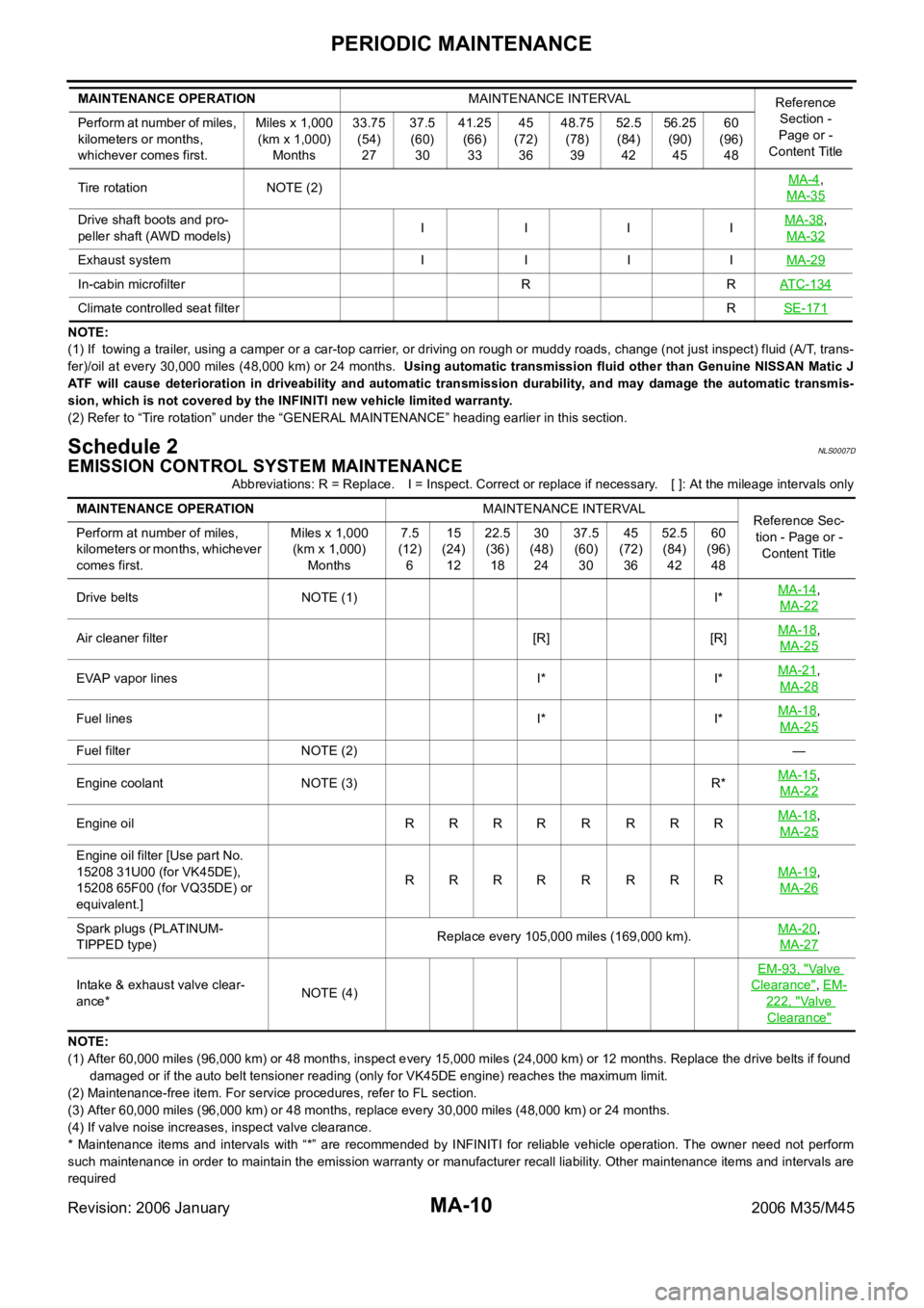
PERIODIC MAINTENANCE
Revision: 2006 January2006 M35/M45
NOTE:
(1) If towing a trailer, using a camper or a car-top carrier, or driving on rough or muddy roads, change (not just inspect) fluid (A/T, trans-
fer)/oil at every 30,000 miles (48,000 km) or 24 months. Using automatic transmission fluid other than Genuine NISSAN Matic J
ATF will cause deterioration in driveability and automatic transmission durability, and may damage the automatic transmis-
sion, which is not covered by the INFINITI new vehicle limited warranty.
(2) Refer to “Tire rotation” under the “GENERAL MAINTENANCE” heading earlier in this section.
Schedule 2NLS0007D
EMISSION CONTROL SYSTEM MAINTENANCE
Abbreviations: R = Replace. I = Inspect. Correct or replace if necessary. [ ]: At the mileage intervals only
NOTE:
(1) After 60,000 miles (96,000 km) or 48 months, inspect every 15,000 miles (24,000 km) or 12 months. Replace the drive belts if found
damaged or if the auto belt tensioner reading (only for VK45DE engine) reaches the maximum limit.
(2) Maintenance-free item. For service procedures, refer to FL section.
(3) After 60,000 miles (96,000 km) or 48 months, replace every 30,000 miles (48,000 km) or 24 months.
(4) If valve noise increases, inspect valve clearance.
* Maintenance items and intervals with “*” are recommended by INFINITI for reliable vehicle operation. The owner need not perform
such maintenance in order to maintain the emission warranty or manufacturer recall liability. Other maintenance items and intervals are
required Tire rotation NOTE (2)MA-4
,
MA-35
Drive shaft boots and pro-
peller shaft (AWD models)I IIIMA-38,
MA-32
Exhaust system I I I IMA-29
In-cabin microfilter R RATC-134
Climate controlled seat filterRSE-171
MAINTENANCE OPERATIONMAINTENANCE INTERVAL
Reference
Section -
Page or -
Content Title Perform at number of miles,
kilometers or months,
whichever comes first.Miles x 1,000
(km x 1,000)
Months33.75
(54)
2737.5
(60)
3041.25
(66)
3345
(72)
3648.75
(78)
3952.5
(84)
4256.25
(90)
4560
(96)
48
MAINTENANCE OPERATIONMAINTENANCE INTERVAL
Reference Sec-
tion - Page or -
Content Title Perform at number of miles,
kilometers or months, whichever
comes first.Miles x 1,000
(km x 1,000)
Months7.5
(12)
615
(24)
1222.5
(36)
1830
(48)
2437.5
(60)
3045
(72)
3652.5
(84)
4260
(96)
48
Drive belts NOTE (1) I*MA-14
,
MA-22
Air cleaner filter [R] [R]MA-18,
MA-25
EVAP vapor lines I* I*MA-21,
MA-28
Fuel lines I* I*MA-18,
MA-25
Fuel filter NOTE (2)—
Engine coolant NOTE (3) R*MA-15
,
MA-22
Engine oil RRRRRRRRMA-18,
MA-25
Engine oil filter [Use part No.
15208 31U00 (for VK45DE),
15208 65F00 (for VQ35DE) or
equivalent.]RRRR R RRRMA-19
,
MA-26
Spark plugs (PLATINUM-
TIPPED type)Replace every 105,000 miles (169,000 km).MA-20,
MA-27
Intake & exhaust valve clear-
ance*NOTE (4)EM-93, "
Va l v e
Clearance", EM-
222, "Va l v e
Clearance"
Page 5086 of 5621

REAR SUSPENSION ASSEMBLY
RSU-5
C
D
F
G
H
I
J
K
L
MA
B
RSU
Revision: 2006 January2006 M35/M45
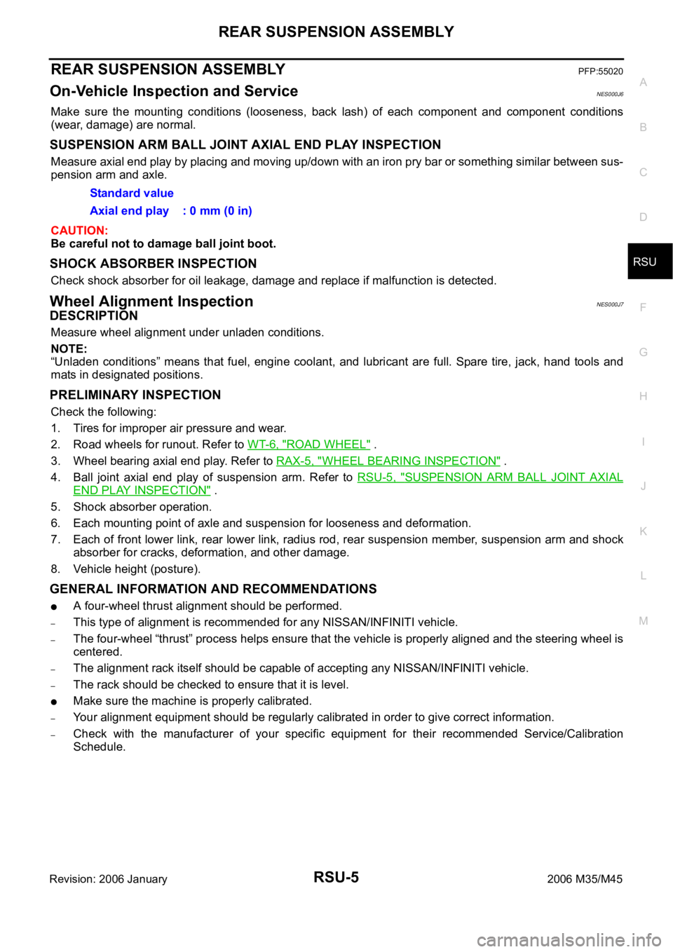
REAR SUSPENSION ASSEMBLYPFP:55020
On-Vehicle Inspection and ServiceNES000J6
Make sure the mounting conditions (looseness, back lash) of each component and component conditions
(wear, damage) are normal.
SUSPENSION ARM BALL JOINT AXIAL END PLAY INSPECTION
Measure axial end play by placing and moving up/down with an iron pry bar or something similar between sus-
pension arm and axle.
CAUTION:
Be careful not to damage ball joint boot.
SHOCK ABSORBER INSPECTION
Check shock absorber for oil leakage, damage and replace if malfunction is detected.
Wheel Alignment InspectionNES000J7
DESCRIPTION
Measure wheel alignment under unladen conditions.
NOTE:
“Unladen conditions” means that fuel, engine coolant, and lubricant are full. Spare tire, jack, hand tools and
mats in designated positions.
PRELIMINARY INSPECTION
Check the following:
1. Tires for improper air pressure and wear.
2. Road wheels for runout. Refer to WT-6, "
ROAD WHEEL" .
3. Wheel bearing axial end play. Refer to RAX-5, "
WHEEL BEARING INSPECTION" .
4. Ball joint axial end play of suspension arm. Refer to RSU-5, "
SUSPENSION ARM BALL JOINT AXIAL
END PLAY INSPECTION" .
5. Shock absorber operation.
6. Each mounting point of axle and suspension for looseness and deformation.
7. Each of front lower link, rear lower link, radius rod, rear suspension member, suspension arm and shock
absorber for cracks, deformation, and other damage.
8. Vehicle height (posture).
GENERAL INFORMATION AND RECOMMENDATIONS
A four-wheel thrust alignment should be performed.
–This type of alignment is recommended for any NISSAN/INFINITI vehicle.
–The four-wheel “thrust” process helps ensure that the vehicle is properly aligned and the steering wheel is
centered.
–The alignment rack itself should be capable of accepting any NISSAN/INFINITI vehicle.
–The rack should be checked to ensure that it is level.
Make sure the machine is properly calibrated.
–Your alignment equipment should be regularly calibrated in order to give correct information.
–Check with the manufacturer of your specific equipment for their recommended Service/Calibration
Schedule.Standard value
Axial end play : 0 mm (0 in)
Page 5533 of 5621

WT-8
ROAD WHEEL TIRE ASSEMBLY
Revision: 2006 January2006 M35/M45
If either residual imbalance value exceeds 7 g (0.25 oz), repeat installation procedures.
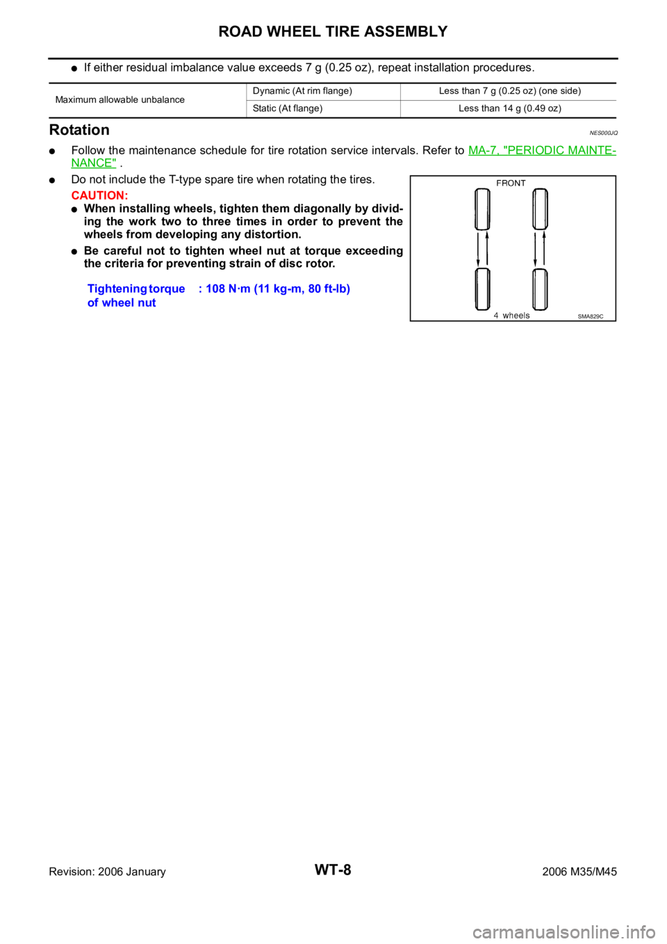
RotationNES000JQ
Follow the maintenance schedule for tire rotation service intervals. Refer to MA-7, "PERIODIC MAINTE-
NANCE" .
Do not include the T-type spare tire when rotating the tires.
CAUTION:
When installing wheels, tighten them diagonally by divid-
ing the work two to three times in order to prevent the
wheels from developing any distortion.
Be careful not to tighten wheel nut at torque exceeding
the criteria for preventing strain of disc rotor.
Maximum allowable unbalanceDynamic (At rim flange) Less than 7 g (0.25 oz) (one side)
Static (At flange) Less than 14 g (0.49 oz)
Tightening torque
of wheel nut: 108 Nꞏm (11 kg-m, 80 ft-lb)
SMA829C