Page 994 of 5621
INTELLIGENT KEY SYSTEM
BL-55
C
D
E
F
G
H
J
K
L
MA
B
BL
Revision: 2006 January2006 M35/M45
WARNING FUNCTION
Operation Description
The warning function are as follows and are given to the user as warning information and warnings using com-
binations of Intelligent Key warning buzzer, KEY warning lamp, key slot illumination and combination meter
display in combination meter.
Intelligent Key system malfunction
OFF position warning
P position warning
ACC warning
Take away warning
Door lock operation warning
Key warning
Intelligent Key insert information
Engine start information
Steering lock information
Intelligent key low battery warning
Key ID warning
Page 996 of 5621

INTELLIGENT KEY SYSTEM
BL-57
C
D
E
F
G
H
J
K
L
MA
B
BL
Revision: 2006 January2006 M35/M45
Warning Method
The following table shows the alarm or warning methods with chime.
Meter display, “KEY” indicator or key slot illumination when the warning conditions are met.
Engine start informationIgnition switch is ON
position
Ignition switch: ON position.
Shift position: P position
Engine is stopped
Ignition switch is except
ON position
Ignition switch: Except ON position.
Shift position: P position
Intelligent Key is inserted in key slot.
Intelligent Key can be detected inside the vehicle.
Steering lock information When steering lock can not be released after ignition switch is turned ON.
Intelligent Key low battery warningWhen Intelligent Key is low battery, Intelligent Key unit is detected after igni-
tion switch is turned ON.
Key ID warningWhen registered Intelligent Key can not be detected inside the vehicle after
ignition switch is turned ON. Warning/Information functions Operation procedure
Warning/Information functions“KEY” warn-
ing lampCombination meter displayKey slot
illuminationWarning chime
Combination
meter buzzerIntelligent
Key warning
buzzer
Intelligent Key system malfunction Illuminate — — — —
OFF position warn-
ing For internal — — — Activate —
For external — — — — Activate
P position warning — — Activate —
ACC warning — — Activate —
Take away warningDoor is open to
close— Flash Activate Activate
Door is open — Flash — —
Push-ignition
switch operation— Flash Activate —
Ta k e a w a y
through window— Flash Activate —
Intelligent Key is
removed from
key slot—Flash——
Door lock opera-
tion warningRequest switch
operation————Activate
Intelligent Key
operation————Activate
PIIB4765J
PIIB4766J
PIIB6452E
Page 997 of 5621
BL-58
INTELLIGENT KEY SYSTEM
Revision: 2006 January2006 M35/M45
Key warning — Flash Activate —
Intelligent Key insert information — Flash — —
Engine start infor-
mationIgnition switch is
ON position————
Ignition switch is
except ON posi-
tion————
Steering lock information — — — —
Intelligent Key low battery warning — — — —
Key ID warning — — — —Warning/Information functions“KEY” warn-
ing lampCombination meter displayKey slot
illuminationWarning chime
Combination
meter buzzerIntelligent
Key warning
buzzer
PIIB4769J
PIIB4768J
PIIB4771J
PIIB4770J
PIIB4772J
PIIB4774J
PIIB4773J
Page 998 of 5621

INTELLIGENT KEY SYSTEM
BL-59
C
D
E
F
G
H
J
K
L
MA
B
BL
Revision: 2006 January2006 M35/M45
List of Operation Related Parts
Parts marked with are the parts related to operation.
Warning function
Intelligent Key
Key slot
Ignition switch
Door switch
Door request switch
Inside key antenna
Outside key antenna
Intelligent Key warning buzzer
Combination meter warning buzzer
Intelligent Key unit
CAN communication system
BCM
Combination meter display
Key slot illumination
Park position switch
“KEY” warning lamp
Intelligent Key system malfunction
OFF position warningFor internalFor external
P position warning
ACC warning
Take away warningDoor is open or close
Door is open
Push-ignition switch
operation
Take away through win-
dow
Intelligent Key is
removed from key slot
Door lock operation warning
Key warning
Intelligent Key insert information
Engine start informationIgnition switch is ON
positionIgnition switch is except
ON position
Steering lock information
Intelligent Key low battery warning
Key ID warning
Page 999 of 5621

BL-60
INTELLIGENT KEY SYSTEM
Revision: 2006 January2006 M35/M45
CHANGE SETTINGS FUNCTION
The settings for each function can be changed with the CONSULT-II.
Changing Settings Using CONSULT-II
The settings for the Intelligent Key system functions can be changed using CONSULT-II (WORK SUPPORT).
Refer to BL-83, "
WORK SUPPORT" .
NOTE:
Once a function setting is changed, it will remain effective even if the battery is disconnected.
INTELLIGENT KEY REGISTRATION
Intelligent Key-ID registration is performed using the CONSULT-II.
CAUTION:
After a new Intelligent Key-ID is registered, be sure to check the function.
When registering an additional Intelligent Key-ID, take any Intelligent Keys already registered and
Intelligent Keys for any other vehicles out of the vehicle before starting.
CONSULT-II can be used to check and delete Intelligent Key-IDs.
For future information, see Technical Bulletin.
STEERING LOCK UNIT REGISTRATION
Steering Lock Unit ID Registration
CAUTION:
The method for registering a steering lock unit ID depends on the status of the steering lock unit
and Intelligent Key unit (new or old unit).
After registration is completed, press ignition switch with an Intelligent Key in the vehicle so that it
can be turned, and confirm that it cannot be turned even when ignition switch is pressed without
an Intelligent Key in the vehicle.
For future information, see Technical Bulletin.
CAN Communication System DescriptionNIS001X9
CAN (Controller Area Network) is a serial communication line for real time application. It is an on-vehicle mul-
tiplex communication line with high data communication speed and excellent error detection ability. Many elec-
tronic control units are equipped onto a vehicle, and each control unit shares information and links with other
control units during operation (not independent). In CAN communication, control units are connected with 2
communication lines (CAN H line, CAN L line) allowing a high rate of information transmission with less wiring.
Each control unit transmits/receives data but selectively reads required data only.
CAN Communication UnitNIS001XA
Refer to LAN-34, "CAN Communication Unit" .
Page 1013 of 5621

BL-74
INTELLIGENT KEY SYSTEM
Revision: 2006 January2006 M35/M45
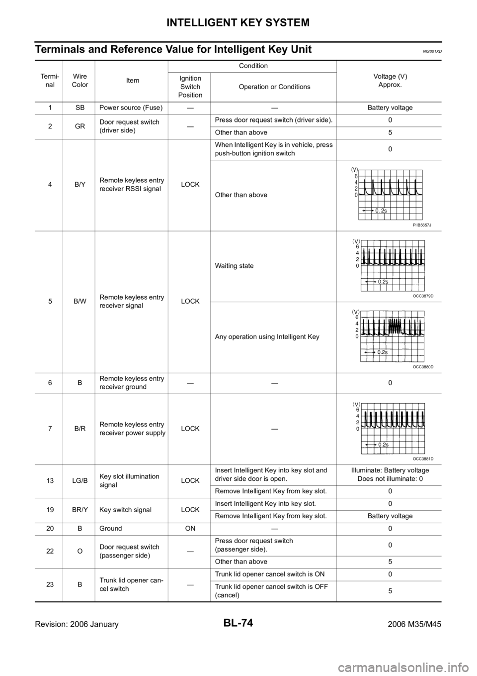
Terminals and Reference Value for Intelligent Key UnitNIS001XD
Te r m i -
nalWire
ColorItemCondition
Voltage (V)
Approx. Ignition
Switch
PositionOperation or Conditions
1 SB Power source (Fuse) — — Battery voltage
2GRDoor request switch
(driver side)—Press door request switch (driver side). 0
Other than above 5
4B/YRemote keyless entry
receiver RSSI signalLOCKWhen Intelligent Key is in vehicle, press
push-button ignition switch0
Other than above
5B/WRemote keyless entry
receiver signalLOCKWaiting state
Any operation using Intelligent Key
6BRemote keyless entry
receiver ground—— 0
7B/RRemote keyless entry
receiver power supplyLOCK —
13 LG/BKey slot illumination
signalLOCKInsert Intelligent Key into key slot and
driver side door is open.Illuminate: Battery voltage
Does not illuminate: 0
Remove Intelligent Key from key slot. 0
19 BR/Y Key switch signal LOCKInsert Intelligent Key into key slot. 0
Remove Intelligent Key from key slot. Battery voltage
20 B Ground ON — 0
22 ODoor request switch
(passenger side)—Press door request switch
(passenger side).0
Other than above 5
23 BTrunk lid opener can-
cel switch—Trunk lid opener cancel switch is ON 0
Trunk lid opener cancel switch is OFF
(cancel)5
PIIB5657J
OCC3879D
OCC3880D
OCC3881D
Page 1014 of 5621

INTELLIGENT KEY SYSTEM
BL-75
C
D
E
F
G
H
J
K
L
MA
B
BL
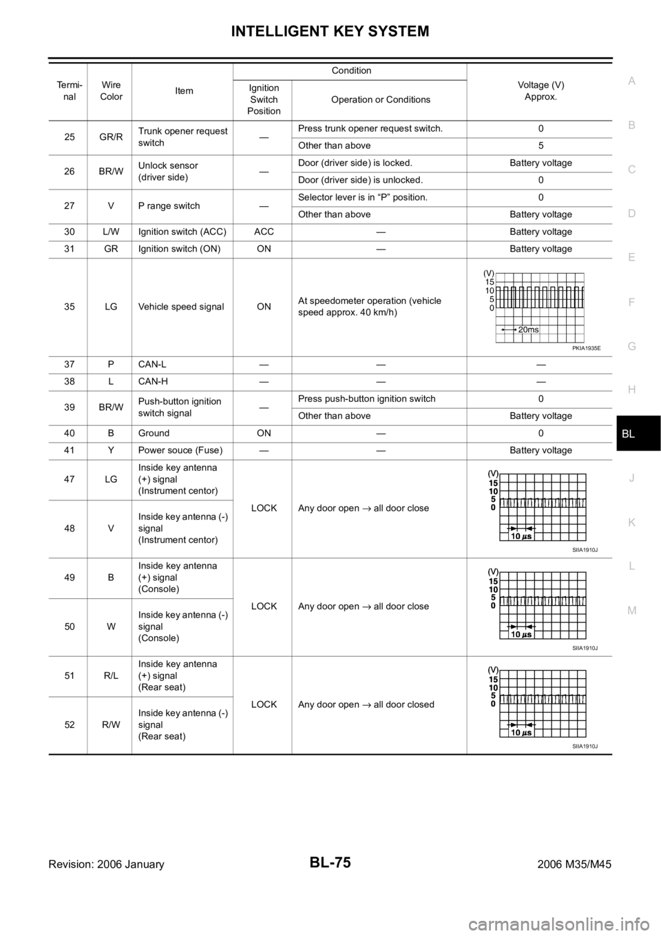
Revision: 2006 January2006 M35/M45
25 GR/RTrunk opener request
switch—Press trunk opener request switch. 0
Other than above 5
26 BR/WUnlock sensor
(driver side)—Door (driver side) is locked. Battery voltage
Door (driver side) is unlocked. 0
27 V P range switch —Selector lever is in “P” position. 0
Other than above Battery voltage
30 L/W Ignition switch (ACC) ACC — Battery voltage
31 GR Ignition switch (ON) ON — Battery voltage
35 LG Vehicle speed signal ONAt speedometer operation (vehicle
speed approx. 40 km/h)
37 P CAN-L — — —
38 L CAN-H — — —
39 BR/WPush-button ignition
switch signal—Press push-button ignition switch 0
Other than above Battery voltage
40 B Ground ON — 0
41 Y Power souce (Fuse) — — Battery voltage
47 LGInside key antenna
(+) signal
(Instrument centor)
LOCK Any door open
all door close
48 VInside key antenna (-)
signal
(Instrument centor)
49 BInside key antenna
(+) signal
(Console)
LOCK Any door open
all door close
50 WInside key antenna (-)
signal
(Console)
51 R/LInside key antenna
(+) signal
(Rear seat)
LOCK Any door open
all door closed
52 R/WInside key antenna (-)
signal
(Rear seat) Te r m i -
nalWire
ColorItemCondition
Voltage (V)
Approx. Ignition
Switch
PositionOperation or Conditions
PKIA1935E
SIIA1910J
SIIA1910J
SIIA1910J
Page 1015 of 5621

BL-76
INTELLIGENT KEY SYSTEM
Revision: 2006 January2006 M35/M45
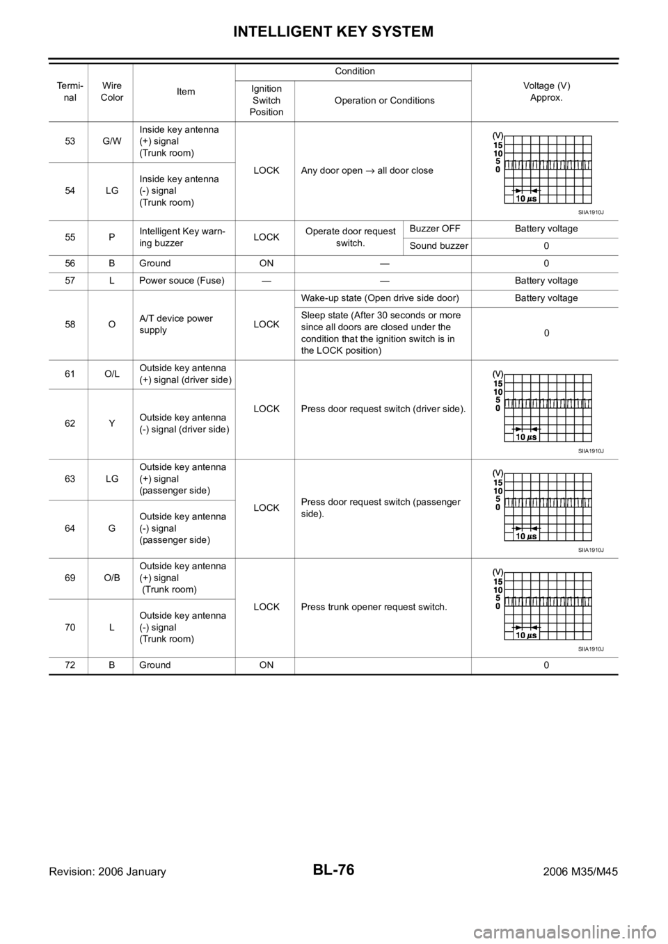
53 G/WInside key antenna
(+) signal
(Trunk room)
LOCK Any door open
all door close
54 LGInside key antenna
(-) signal
(Trunk room)
55 PIntelligent Key warn-
ing buzzerLOCKOperate door request
switch.Buzzer OFF Battery voltage
Sound buzzer 0
56 B Ground ON — 0
57 L Power souce (Fuse) — — Battery voltage
58 OA/T device power
supply LOCKWake-up state (Open drive side door) Battery voltage
Sleep state (After 30 seconds or more
since all doors are closed under the
condition that the ignition switch is in
the LOCK position)0
61 O/LOutside key antenna
(+) signal (driver side)
LOCK Press door request switch (driver side).
62 YOutside key antenna
(-) signal (driver side)
63 LGOutside key antenna
(+) signal
(passenger side)
LOCKPress door request switch (passenger
side).
64 GOutside key antenna
(-) signal
(passenger side)
69 O/BOutside key antenna
(+) signal
(Trunk room)
LOCK Press trunk opener request switch.
70 LOutside key antenna
(-) signal
(Trunk room)
72 B Ground ON 0 Te r m i -
nalWire
ColorItemCondition
Voltage (V)
Approx. Ignition
Switch
PositionOperation or Conditions
SIIA1910J
SIIA1910J
SIIA1910J
SIIA1910J