2006 INFINITI M35 Tail light
[x] Cancel search: Tail lightPage 948 of 5621

SQUEAK AND RATTLE TROUBLE DIAGNOSIS
BL-9
C
D
E
F
G
H
J
K
L
MA
B
BL
Revision: 2006 January2006 M35/M45
SQUEAK AND RATTLE TROUBLE DIAGNOSISPFP:00000
Work FlowNIS001WG
CUSTOMER INTERVIEW
Interview the customer if possible, to determine the conditions that exist when the noise occurs.Use the Diag-
nostic Worksheet during the interview to document the facts and conditions when the noise occurs and any
customer's comments; refer to BL-13, "
Diagnostic Worksheet" . This information is necessary to duplicate the
conditions that exist when the noise occurs.
The customer may not be able to provide a detailed description or the location of the noise. Attempt to
obtain all the facts and conditions that exist when the noise occurs (or does not occur).
If there is more than one noise in the vehicle, be sure to diagnose and repair the noise that the customer
is concerned about. This can be accomplished by test driving the vehicle with the customer.
After identifying the type of noise, isolate the noise in terms of its characteristics. The noise characteristics
are provided so the customer, service adviser and technician are all speaking the same language when
defining the noise.
Squeak —(Like tennis shoes on a clean floor)
Squeak characteristics include the light contact/fast movement/brought on by road conditions/hard sur-
faces=higher pitch noise/softer surfaces=lower pitch noises/edge to surface=chirping
Creak—(Like walking on an old wooden floor)
Creak characteristics include firm contact/slow movement/twisting with a rotational movement/pitch
dependent on materials/often brought on by activity.
Rattle—(Like shaking a baby rattle)
Rattle characteristics include the fast repeated contact/vibration or similar movement/loose parts/missing
clip or fastener/incorrect clearance.
Knock —(Like a knock on a door)
Knock characteristics include hollow sounding/sometimes repeating/often brought on by driver action.
Tick—(Like a clock second hand)
Tick characteristics include gentle contacting of light materials/loose components/can be caused by driver
action or road conditions.
Thump—(Heavy, muffled knock noise)
Thump characteristics include softer knock/dead sound often brought on by activity.
Buzz—(Like a bumble bee)
Buzz characteristics include high frequency rattle/firm contact.
Often the degree of acceptable noise level will vary depending upon the person. A noise that you may
judge as acceptable may be very irritating to the customer.
Weather conditions, especially humidity and temperature, may have a great effect on noise level.
SBT842
Page 1221 of 5621

BL-282
INTEGRATED HOMELINK TRANSMITTER
Revision: 2006 January2006 M35/M45
Trouble DiagnosesNIS0020W
DIAGNOSTIC PROCEDURE
SYMPTOM: Transmitter does not activate receiver.
Before conducting the procedure given below, make sure that system receiver (garage door opener, etc.)
operates with original, hand-held transmitter. If NG, receiver or hand-held transmitter is malfunctioning, not
vehicle related.
1. ILLUMINATE CHECK
1. Turn ignition switch “OFF”.
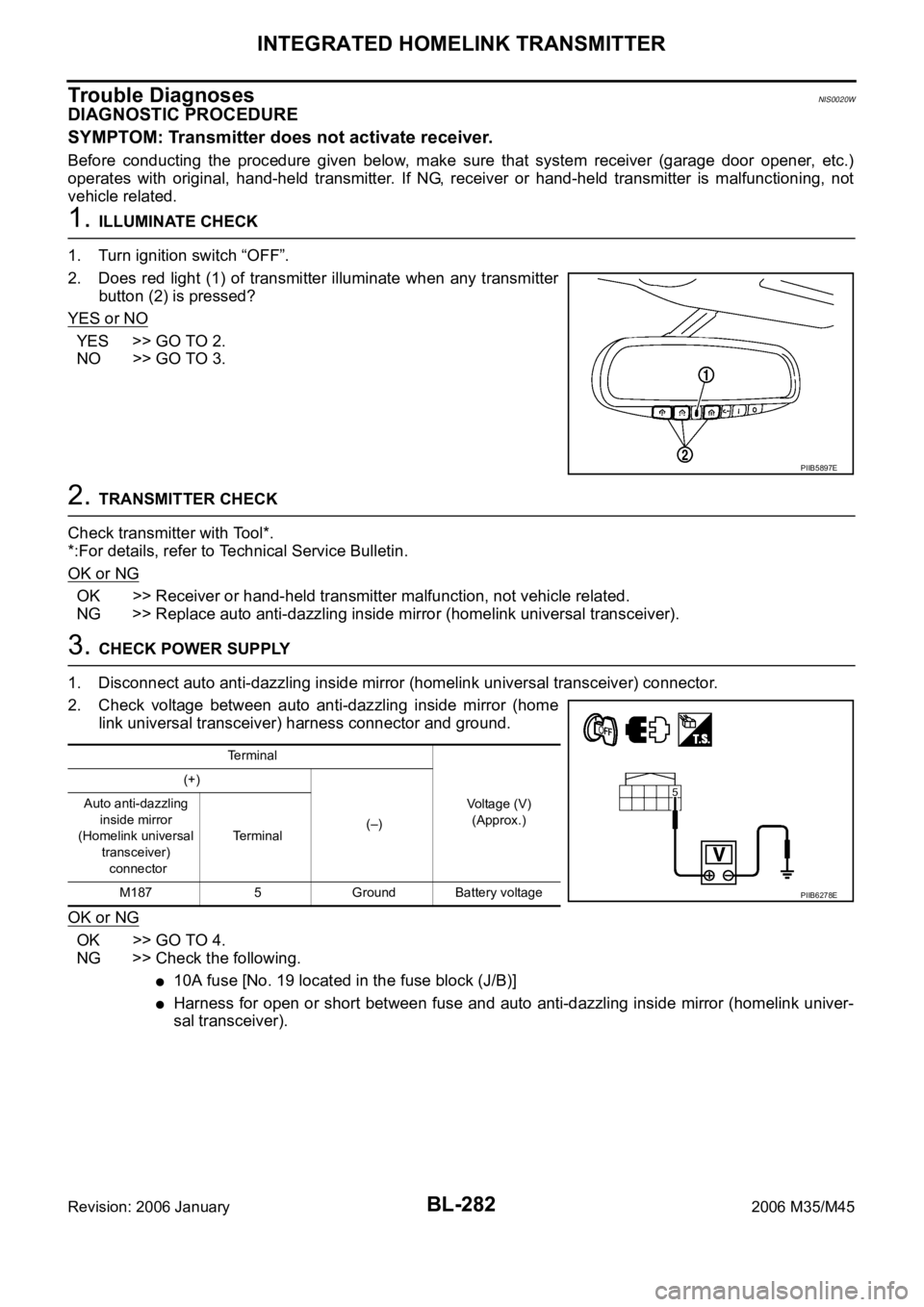
2. Does red light (1) of transmitter illuminate when any transmitter
button (2) is pressed?
YES or NO
YES >> GO TO 2.
NO >> GO TO 3.
2. TRANSMITTER CHECK
Check transmitter with Tool*.
*:For details, refer to Technical Service Bulletin.
OK or NG
OK >> Receiver or hand-held transmitter malfunction, not vehicle related.
NG >> Replace auto anti-dazzling inside mirror (homelink universal transceiver).
3. CHECK POWER SUPPLY
1. Disconnect auto anti-dazzling inside mirror (homelink universal transceiver) connector.
2. Check voltage between auto anti-dazzling inside mirror (home
link universal transceiver) harness connector and ground.
OK or NG
OK >> GO TO 4.
NG >> Check the following.
10A fuse [No. 19 located in the fuse block (J/B)]
Harness for open or short between fuse and auto anti-dazzling inside mirror (homelink univer-
sal transceiver).
PIIB5897E
Terminal
Voltage (V)
(Approx.) (+)
(–) Auto anti-dazzling
inside mirror
(Homelink universal
transceiver)
connectorTerminal
M187 5 Ground Battery voltage
PIIB6278E
Page 1494 of 5621

WARNING CHIME
DI-61
C
D
E
F
G
H
I
J
L
MA
B
DI
Revision: 2006 January2006 M35/M45
IGNITION KEY WARNING CHIME (WITH INTELLIGENT KEY)
Refer to BL-55, "WARNING FUNCTION" in intelligent key system.
LIGHT WARNING CHIME
With ignition switch in OFF or ACC position, driver door open, and lighting switch in 1ST or 2ND position, the
light warning chime will sound.
BCM detects ignition switch in OFF or ACC position, front door switch (driver side) ON, and lighting switch
in 1ST or 2ND position. And then transmits buzzer output signal (light warning chime) to unified meter and
A/C amp. with CAN communication line.
Unified meter and A/C amp. transmits buzzer output signal (light warning chime) to combination meter
with communication line.
When combination meter receives buzzer output signal (light warning chime), it sounds the buzzer.
NOTE:
For further details of combination switch, refer to BCS-3, "
COMBINATION SWITCH READING FUNCTION" .
SEAT BELT WARNING CHIME
With ignition switch turned ON and driver seat belt unfastened, seat belt warning chime will sound for approxi-
mately 6 seconds.
BCM receives seat belt buckle switch signal [seat belt buckle switch (driver side) ON] from unified meter
and A/C amp. with CAN communication line.
BCM detects ignition switch turned ON and seat belt buckle switch (driver side) ON. And then transmits
buzzer output signal (seat belt warning chime) to unified meter and A/C amp. with CAN communication
line.
Unified meter and A/C amp. transmits buzzer output signal (seat belt warning chime) to combination
meter with communication line.
When combination meter receives buzzer output signal (seat belt warning chime), it sounds the buzzer.
SKIB3858E
SKIB3859E
Page 1503 of 5621

DI-70
WARNING CHIME
Revision: 2006 January2006 M35/M45
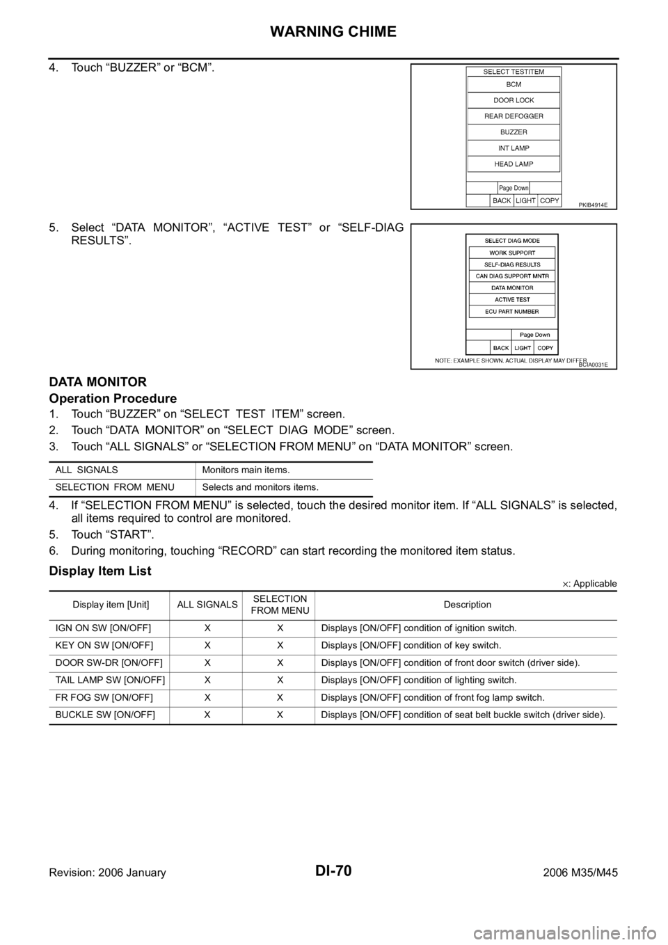
4. Touch “BUZZER” or “BCM”.
5. Select “DATA MONITOR”, “ACTIVE TEST” or “SELF-DIAG
RESULTS”.
DATA MONITOR
Operation Procedure
1. Touch “BUZZER” on “SELECT TEST ITEM” screen.
2. Touch “DATA MONITOR” on “SELECT DIAG MODE” screen.
3. Touch “ALL SIGNALS” or “SELECTION FROM MENU” on “DATA MONITOR” screen.
4. If “SELECTION FROM MENU” is selected, touch the desired monitor item. If “ALL SIGNALS” is selected,
all items required to control are monitored.
5. Touch “START”.
6. During monitoring, touching “RECORD” can start recording the monitored item status.
Display Item List
: Applicable
PKIB4914E
BCIA0031E
ALL SIGNALS Monitors main items.
SELECTION FROM MENU Selects and monitors items.
Display item [Unit] ALL SIGNALSSELECTION
FROM MENUDescription
IGN ON SW [ON/OFF] X X Displays [ON/OFF] condition of ignition switch.
KEY ON SW [ON/OFF] X X Displays [ON/OFF] condition of key switch.
DOOR SW-DR [ON/OFF] X X Displays [ON/OFF] condition of front door switch (driver side).
TAIL LAMP SW [ON/OFF] X X Displays [ON/OFF] condition of lighting switch.
FR FOG SW [ON/OFF] X X Displays [ON/OFF] condition of front fog lamp switch.
BUCKLE SW [ON/OFF] X X Displays [ON/OFF] condition of seat belt buckle switch (driver side).
Page 1504 of 5621

WARNING CHIME
DI-71
C
D
E
F
G
H
I
J
L
MA
B
DI
Revision: 2006 January2006 M35/M45
ACTIVE TEST
Operation Procedure
1. Touch “BUZZER” on “SELECT TEST ITEM” screen.
2. Touch “ACTIVE TEST” on “SELECT DIAG MODE” screen.
3. Touch the item to be tested, and check the operation.
4. During the operation check, touching “OFF” deactivates the operation.
Display Item List
SELF-DIAG RESULTS
Operation Procedure
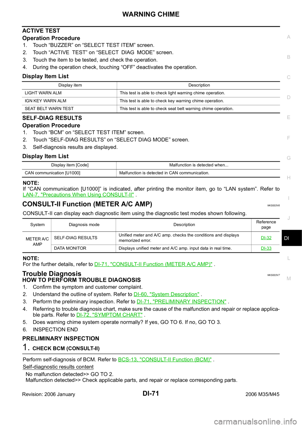
1. Touch “BCM” on “SELECT TEST ITEM” screen.
2. Touch “SELF-DIAG RESULTS” on “SELECT DIAG MODE” screen.
3. Self-diagnosis results are displayed.
Display Item List
NOTE:
If “CAN communication [U1000]” is indicated, after printing the monitor item, go to “LAN system”. Refer to
LAN-7, "
Precautions When Using CONSULT-II" .
CONSULT-II Function (METER A/C AMP)NKS003V6
CONSULT-II can display each diagnostic item using the diagnostic test modes shown following.
NOTE:
For the further details, refer to DI-71, "
CONSULT-II Function (METER A/C AMP)" .
Trouble DiagnosisNKS003V7
HOW TO PERFORM TROUBLE DIAGNOSIS
1. Confirm the symptom and customer complaint.
2. Understand the outline of system. Refer to DI-60, "
System Description" .
3. Perform the preliminary inspection. Refer to DI-71, "
PRELIMINARY INSPECTION" .
4. Referring to trouble diagnosis chart, make sure the cause of the malfunction and repair or replace applica-
ble parts. Refer to DI-72, "
SYMPTOM CHART" .
5. Does warning chime system operate normally? If yes, GO TO 6. If no, GO TO 3.
6. INSPECTION END
PRELIMINARY INSPECTION
1. CHECK BCM (CONSULT-II)
Perform self-diagnosis of BCM. Refer to BCS-13, "
CONSULT-II Function (BCM)" .
Self
-diagnostic results content
No malfunction detected>> GO TO 2.
Malfunction detected>> Check applicable parts, and repair or replace corresponding parts.
Display item Description
LIGHT WARN ALM This test is able to check light warning chime operation.
IGN KEY WARN ALM This test is able to check key warning chime operation.
SEAT BELT WARN TEST This test is able to check seat belt warning chime operation.
Display item [Code] Malfunction is detected when...
CAN communication [U1000] Malfunction is detected in CAN communication.
System Diagnosis mode DescriptionReference
page
METER A/C
AMPSELF-DIAG RESULTSUnified meter and A/C amp. checks the conditions and displays
memorized error.DI-32
DATA MONITOR Displays unified meter and A/C amp. input data in real time.DI-33
Page 1506 of 5621

WARNING CHIME
DI-73
C
D
E
F
G
H
I
J
L
MA
B
DI
Revision: 2006 January2006 M35/M45
4. CHECK BATTERY POWER SUPPLY OF UNIFIED METER AND A/C AMP.
Check battery power supply of unified meter and A/C amp. Refer to DI-35, "
Power Supply and Ground Circuit
Inspection" in unified meter and A/C amp.
OK or NG
OK >> Replace BCM. Refer to BCS-17, "Removal and Installation of BCM" .
NG >> Repair battery power supply circuit of unified meter and A/C amp.
Lighting Switch Signal InspectionNKS003V9
1. CHECK BCM INPUT SIGNAL
1. Select “BCM” on CONSULT-II.
2. With “DATA MONITOR” of “BUZZER”, confirm “TAIL LAMP SW”
when the lighting switch is operated.
OK or NG
OK >> Lighting switch signal is OK. Return to DI-72, "SYMP-
TOM CHART" .
NG >> Check the lighting switch. Refer to LT- 2 3 0 , "
Switch Cir-
cuit Inspection" .
Front Door Switch (Driver Side) Signal InspectionNKS003VA
1. CHECK BCM INPUT SIGNAL
With CONSULT-ll
1. Select “BCM” on CONSULT-II.
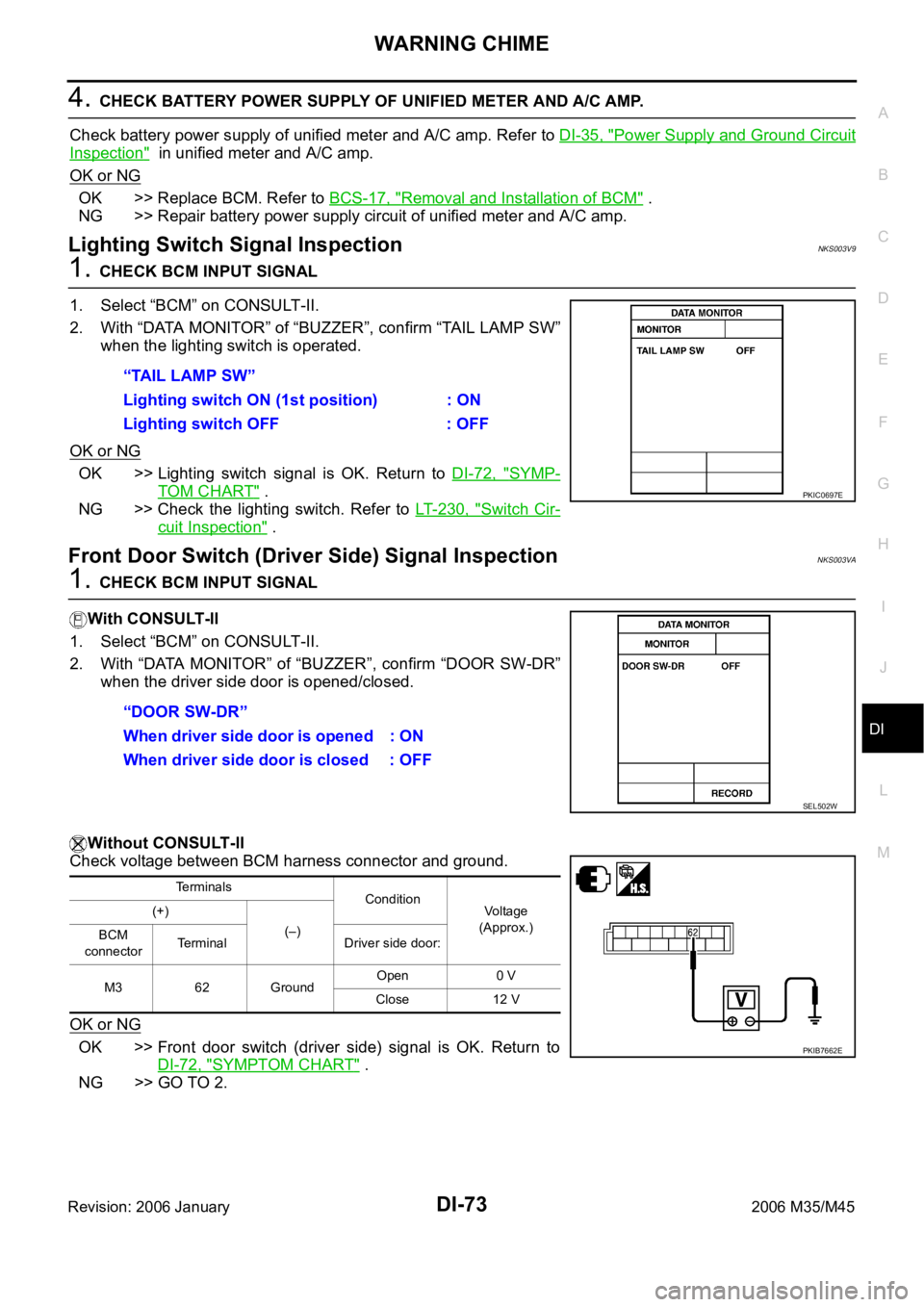
2. With “DATA MONITOR” of “BUZZER”, confirm “DOOR SW-DR”
when the driver side door is opened/closed.
Without CONSULT-ll
Check voltage between BCM harness connector and ground.
OK or NG
OK >> Front door switch (driver side) signal is OK. Return to
DI-72, "
SYMPTOM CHART" .
NG >> GO TO 2.“TAIL LAMP SW”
Lighting switch ON (1st position) : ON
Lighting switch OFF : OFF
PKIC0697E
“DOOR SW-DR”
When driver side door is opened : ON
When driver side door is closed : OFF
SEL502W
Terminals
Condition
Voltage
(Approx.) (+)
(–)
BCM
connectorTerminal Driver side door:
M3 62 GroundOpen 0 V
Close 12 V
PKIB7662E
Page 1601 of 5621
![INFINITI M35 2006 Factory Service Manual EC-58
[VQ35DE]
ON BOARD DIAGNOSTIC (OBD) SYSTEM
Revision: 2006 January2006 M35/M45
*1: 1st trip DTC No. is the same as DTC No.
*2: This number is prescribed by SAE J2012.
*3: In Diagnostic Test Mode I INFINITI M35 2006 Factory Service Manual EC-58
[VQ35DE]
ON BOARD DIAGNOSTIC (OBD) SYSTEM
Revision: 2006 January2006 M35/M45
*1: 1st trip DTC No. is the same as DTC No.
*2: This number is prescribed by SAE J2012.
*3: In Diagnostic Test Mode I](/manual-img/42/57023/w960_57023-1600.png)
EC-58
[VQ35DE]
ON BOARD DIAGNOSTIC (OBD) SYSTEM
Revision: 2006 January2006 M35/M45
*1: 1st trip DTC No. is the same as DTC No.
*2: This number is prescribed by SAE J2012.
*3: In Diagnostic Test Mode II (Self-diagnostic results), this number is controlled by NISSAN.
*4: The troubleshooting for this DTC needs CONSULT-II.
*5: When the fail-safe operations for both self-diagnoses occur at the same time, the MIL illuminates.
*6: Models with ICC.
*7: SRT code will not be set if the self-diagnostic result is NG.
*8: When the ECM is in the mode of displaying SRT status, MIL may flash. For the details, refer to EC-62, "
How to Display SRT Status" .
DTC AND 1ST TRIP DTC
The 1st trip DTC (whose number is the same as the DTC number) is displayed for the latest self-diagnostic
result obtained. If the ECM memory was cleared previously, and the 1st trip DTC did not reoccur, the 1st trip
DTC will not be displayed.
If a malfunction is detected during the 1st trip, the 1st trip DTC is stored in the ECM memory. The MIL will not
light up (two trip detection logic). If the same malfunction is not detected in the 2nd trip (meeting the required
driving pattern), the 1st trip DTC is cleared from the ECM memory. If the same malfunction is detected in the
2nd trip, both the 1st trip DTC and DTC are stored in the ECM memory and the MIL lights up. In other words,
ASCD VHL SPD SEN P1574 1574 — — 1 — EC-593 (Models with ICC)
EC-595
(Models with ASCD)
NATS MALFUNCTIONP1610 -
P16151610 - 1615 — — 2 —EC-53
TP SEN/CIRC A/T P1705 1705 — — 1AT-132
IN PULY SPEED P1715 1715 — — 2 —EC-597
A/T INTERLOCK P1730 1730 — — 1AT-142
I/C SOLENOID/CIRC P1752 1752 — — 1AT-147
I/C SOLENOID FNCTN P1754 1754 — — 1AT-149
FR/B SOLENOID/CIRC P1757 1757 — — 1AT-151
FR/B SOLENOID FNCT P1759 1759 — — 1AT-153
D/C SOLENOID/CIRC P1762 1762 — — 1AT-155
D/C SOLENOID FNCTN P1764 1764 — — 1AT-157
HLR/C SOL/CIRC P1767 1767 — — 1AT-159
HLR/C SOL FNCTN P1769 1769 — — 1AT-161
LC/B SOLENOID/CIRC P1772 1772 — — 1AT-163
LC/B SOLENOID FNCT P1774 1774 — — 1AT-165
BRAKE SW/CIRCUIT P1805 1805 — — 2 —EC-598
ETC MOT PWR P2100 2100 — — 1EC-607
ETC FUNCTION/CIRC P2101 2101 — — 1EC-613
ETC MOT PWR P2103 2103 — — 1EC-607
ETC MOT P2118 2118 — — 1EC-619
ETC ACTR P2119 2119 — — 1EC-624
APP SEN 1/CIRC P2122 2122 — — 1EC-626
APP SEN 1/CIRC P2123 2123 — — 1EC-626
APP SEN 2/CIRC P2127 2127 — — 1EC-633
APP SEN 2/CIRC P2128 2128 — — 1EC-633
TP SENSOR P2135 2135 — — 1EC-640
APP SENSOR P2138 2138 — — 1EC-647
A/F SENSOR1 (B1) P2A00 2A00 —2EC-655
A/F SENSOR1 (B2) P2A03 2A03 —2EC-655
Items
(CONSULT-II screen terms)DTC*
1
SRT codeTest value/
Te s t l i m i t
(GST only)Trip MIL Reference page
CONSULT-II
GST*
2ECM*3
Page 1602 of 5621
![INFINITI M35 2006 Factory Service Manual ON BOARD DIAGNOSTIC (OBD) SYSTEM
EC-59
[VQ35DE]
C
D
E
F
G
H
I
J
K
L
MA
EC
Revision: 2006 January2006 M35/M45
the DTC is stored in the ECM memory and the MIL lights up when the same malfunction occurs INFINITI M35 2006 Factory Service Manual ON BOARD DIAGNOSTIC (OBD) SYSTEM
EC-59
[VQ35DE]
C
D
E
F
G
H
I
J
K
L
MA
EC
Revision: 2006 January2006 M35/M45
the DTC is stored in the ECM memory and the MIL lights up when the same malfunction occurs](/manual-img/42/57023/w960_57023-1601.png)
ON BOARD DIAGNOSTIC (OBD) SYSTEM
EC-59
[VQ35DE]
C
D
E
F
G
H
I
J
K
L
MA
EC
Revision: 2006 January2006 M35/M45
the DTC is stored in the ECM memory and the MIL lights up when the same malfunction occurs in two consec-
utive trips. If a 1st trip DTC is stored and a non-diagnostic operation is performed between the 1st and 2nd
trips, only the 1st trip DTC will continue to be stored. For malfunctions that blink or light up the MIL during the
1st trip, the DTC and 1st trip DTC are stored in the ECM memory.
Procedures for clearing the DTC and the 1st trip DTC from the ECM memory are described in EC-67, "
HOW
TO ERASE EMISSION-RELATED DIAGNOSTIC INFORMATION" .
For malfunctions in which 1st trip DTCs are displayed, refer to EC-55, "
EMISSION-RELATED DIAGNOSTIC
INFORMATION ITEMS" . These items are required by legal regulations to continuously monitor the system/
component. In addition, the items monitored non-continuously are also displayed on CONSULT-II.
1st trip DTC is specified in Service $07 of SAE J1979. 1st trip DTC detection occurs without lighting up the MIL
and therefore does not warn the driver of a malfunction. However, 1st trip DTC detection will not prevent the
vehicle from being tested, for example during Inspection/Maintenance (I/M) tests.
When a 1st trip DTC is detected, check, print out or write down and erase (1st trip) DTC and Freeze Frame
data as specified in Work Flow procedure Step 2, refer to EC-101, "
WORK FLOW" . Then perform DTC Con-
firmation Procedure or Overall Function Check to try to duplicate the malfunction. If the malfunction is dupli-
cated, the item requires repair.
How to Read DTC and 1st Trip DTC
DTC and 1st trip DTC can be read by the following methods.
With CONSULT-II
With GST
CONSULT-II or GST (Generic Scan Tool) Examples: P0340, P0850, P11 4 8 , e t c .
These DTCs are prescribed by SAE J2012.
(CONSULT-II also displays the malfunctioning component or system.)
No Tools
The number of blinks of the MIL in the Diagnostic Test Mode II (Self-Diagnostic Results) indicates the DTC.
Example: 0340, 0850, 1148, etc.
These DTCs are controlled by NISSAN.
1st trip DTC No. is the same as DTC No.
Output of a DTC indicates a malfunction. However, GST or the Diagnostic Test Mode II do not indi-
cate whether the malfunction is still occurring or has occurred in the past and has returned to nor-
mal. CONSULT-II can identify malfunction status as shown below. Therefore, using CONSULT-II (if
available) is recommended.
A sample of CONSULT-II display for DTC and 1st trip DTC is shown below. DTC or 1st trip DTC of a malfunc-
tion is displayed in SELF-DIAGNOSTIC RESULTS mode of CONSULT-II. Time data indicates how many times
the vehicle was driven after the last detection of a DTC.
If the DTC is being detected currently, the time data will be [0].
If a 1st trip DTC is stored in the ECM, the time data will be [1t].
FREEZE FRAME DATA AND 1ST TRIP FREEZE FRAME DATA
The ECM records the driving conditions such as fuel system status, calculated load value, engine coolant tem-
perature, short term fuel trim, long term fuel trim, engine speed, vehicle speed, absolute throttle position, base
fuel schedule and intake air temperature at the moment a malfunction is detected.
Data which are stored in the ECM memory, along with the 1st trip DTC, are called 1st trip freeze frame data.
The data, stored together with the DTC data, are called freeze frame data and displayed on CONSULT-II or
GST. The 1st trip freeze frame data can only be displayed on the CONSULT-II screen, not on the GST. For
details, see EC-137, "
Freeze Frame Data and 1st Trip Freeze Frame Data" .
Only one set of freeze frame data (either 1st trip freeze frame data or freeze frame data) can be stored in the
ECM. 1st trip freeze frame data is stored in the ECM memory along with the 1st trip DTC. There is no priority
PBIB0911E