2006 INFINITI M35 sensor
[x] Cancel search: sensorPage 4566 of 5621

ACTIVE AFS
LT-139
C
D
E
F
G
H
I
J
L
MA
B
LT
Revision: 2006 January2006 M35/M45
HEADLAMP AUTO AIMING OPERATION
The height sensor detects a change in height of rear vehicle with ignition switch ON, and transmits signals to
the AFS control unit:
When ignition switch is turn to ON position, power is supplied
to height sensor terminal 1
through AFS control unit terminal 6.
When ignition switch is turned to ON position, height sensor input signal is supplied
to AFS control unit terminal 28
through height sensor terminal 2.
Ground is supplied
to height sensor terminal 3
through AFS control unit terminal 8.
Aiming motor driving signal (voltage signal that corresponds to the vehicle height) is transmitted depending on
the height sensor signal at the start of the engine
to front combination lamp LH terminal 12
through AFS control unit terminal 40,
to front combination lamp RH terminal 12
through AFS control unit terminal 19.
Output of aiming motor driving signal is maintained unless headlamp (HIGH/LOW) illuminate detected.
Auto aiming control operation starts when headlamps (HIGH/LOW) illuminate detected.
When headlamps (HIGH/LOW) illuminate, output of aiming motor driving signal is changed according to the
height sensor signal. After the change, it is changed according to height sensor signals with predetermined
timing based on driving condition while headlamps are ON.
Auto Aiming Operation
AFS control unit starts outputting aiming motor drive signal when the engine starts, and continues to output it
until the engine stops. Aiming motor drive signal changes output when the specified conditions described
below are met.
Headlamp aiming motors set the low beam projectors according to aiming motor drive signals received from
AFS control unit, both headlamp aiming motors cause the low beam projectors to move to the position com-
manded by the signal.
The aiming motor drive signal level retains when the following conditions are not met.
AFS control unit operation when the vehicle is stopped (low beam headlamps illuminated)
Headlamp aiming motor drive signal is changed when vehicle height is stabilized with a parked condition,
depending on the height sensor signal detected with height sensor signal by AFS control unit.
AFS control unit operation when the vehicle is running (low beam headlamps illuminated)
When vehicle is running, headlamp aiming motor drive signal is changed depending on the height sensor
signal which is detected when AFS control unit detects constant steady speed of vehicle.
When the vehicle is accelerating or decelerating, AFS control unit keeps headlamp aiming motor drive sig-
nal voltage level rather than changing it, so that the low beam projectors of both headlamps do not oper-
ate.
CAN COMMUNICATION SYSTEM DESCRIPTION
CAN (Controller Area Network) is a serial communication line for real time application. It is an on-vehicle mul-
tiplex communication line with high data communication speed and excellent error detection ability. Many elec-
tronic control units are equipped onto a vehicle, and each control unit shares information and links with other
control units during operation (not independent). In CAN communication, control units are connected with 2
communication lines (CAN H line, CAN L line) allowing a high rate of information transmission with less wiring.
Each control unit transmits/receives data but selectively reads required data only.
CAN COMMUNICATION UNIT
Refer to LAN-34, "CAN Communication Unit" .
Page 4567 of 5621
LT-140
ACTIVE AFS
Revision: 2006 January2006 M35/M45
Component Parts DescriptionNKS003QG
AFS CONTROL UNIT
AFS control unit determines current vehicle conditions by received signals and controls AFS and headlamp
auto aiming.
SWIVEL ACTUATOR
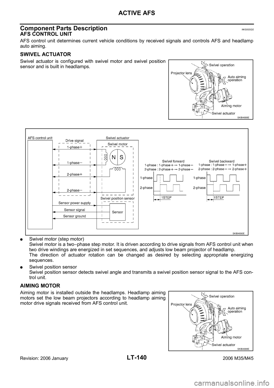
Swivel actuator is configured with swivel motor and swivel position
sensor and is built in headlamps.
Swivel motor (step motor)
Swivel motor is a two
phase step motor. It is driven according to drive signals from AFS control unit when
two drive windings are energized in set sequences, and adjusts low beam projector of headlamp.
The direction of actuator rotation can be changed as desired by selecting appropriate energizing
sequences.
Swivel position sensor
Swivel position sensor detects swivel angle and transmits a swivel position sensor signal to the AFS con-
trol unit.
AIMING MOTOR
Aiming motor is installed outside the headlamps. Headlamp aiming
motors set the low beam projectors according to headlamp aiming
motor drive signals received from AFS control unit.
SKIB4688E
SKIB4690E
SKIB4688E
Page 4568 of 5621
ACTIVE AFS
LT-141
C
D
E
F
G
H
I
J
L
MA
B
LT
Revision: 2006 January2006 M35/M45
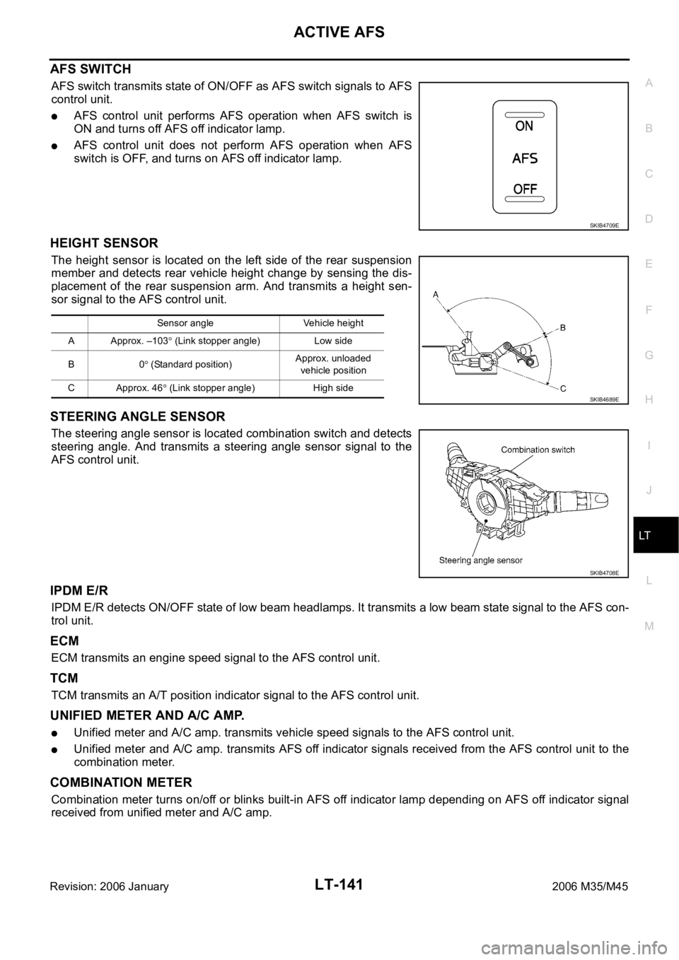
AFS SWITCH
AFS switch transmits state of ON/OFF as AFS switch signals to AFS
control unit.
AFS control unit performs AFS operation when AFS switch is
ON and turns off AFS off indicator lamp.
AFS control unit does not perform AFS operation when AFS
switch is OFF, and turns on AFS off indicator lamp.
HEIGHT SENSOR
The height sensor is located on the left side of the rear suspension
member and detects rear vehicle height change by sensing the dis-
placement of the rear suspension arm. And transmits a height sen-
sor signal to the AFS control unit.
STEERING ANGLE SENSOR
The steering angle sensor is located combination switch and detects
steering angle. And transmits a steering angle sensor signal to the
AFS control unit.
IPDM E/R
IPDM E/R detects ON/OFF state of low beam headlamps. It transmits a low beam state signal to the AFS con-
trol unit.
ECM
ECM transmits an engine speed signal to the AFS control unit.
TCM
TCM transmits an A/T position indicator signal to the AFS control unit.
UNIFIED METER AND A/C AMP.
Unified meter and A/C amp. transmits vehicle speed signals to the AFS control unit.
Unified meter and A/C amp. transmits AFS off indicator signals received from the AFS control unit to the
combination meter.
COMBINATION METER
Combination meter turns on/off or blinks built-in AFS off indicator lamp depending on AFS off indicator signal
received from unified meter and A/C amp.
SKIB4709E
Sensor angle Vehicle height
A Approx. –103
(Link stopper angle) Low side
B0
(Standard position)Approx. unloaded
vehicle position
C Approx. 46
(Link stopper angle) High side SKIB4689E
SKIB4708E
Page 4576 of 5621
ACTIVE AFS
LT-149
C
D
E
F
G
H
I
J
L
MA
B
LT
Revision: 2006 January2006 M35/M45
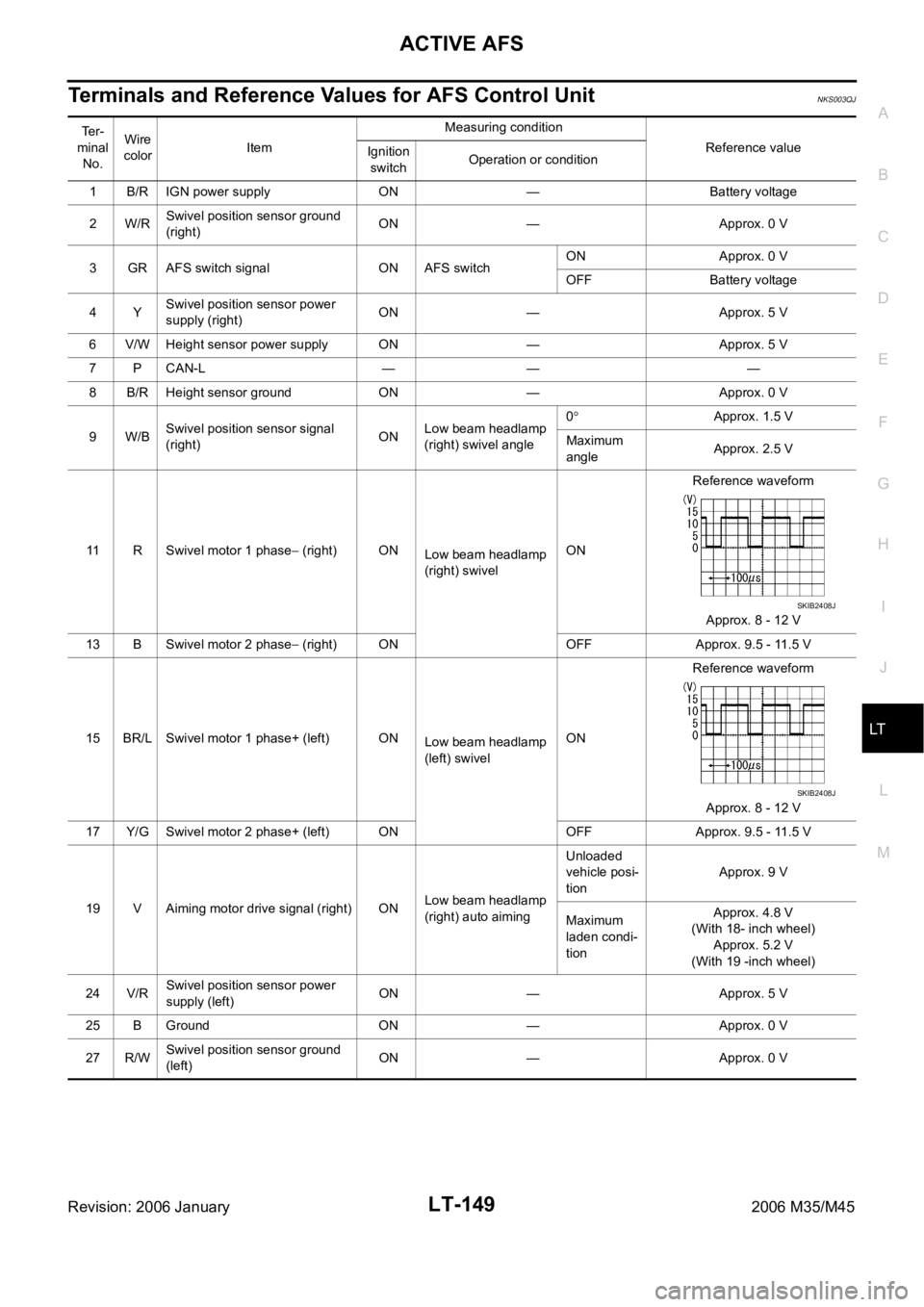
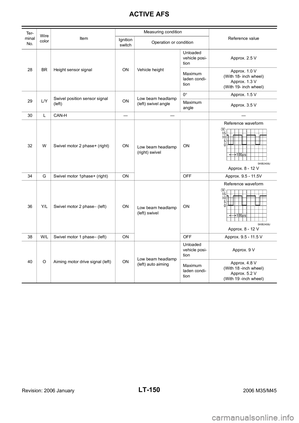
Terminals and Reference Values for AFS Control UnitNKS003QJ
Te r -
minal
No.Wire
colorItemMeasuring condition
Reference value
Ignition
switchOperation or condition
1 B/R IGN power supply ON — Battery voltage
2W/RSwivel position sensor ground
(right)ON — Approx. 0 V
3 GR AFS switch signal ON AFS switchON Approx. 0 V
OFF Battery voltage
4YSwivel position sensor power
supply (right)ON — Approx. 5 V
6 V/W Height sensor power supply ON — Approx. 5 V
7 P CAN-L — — —
8 B/R Height sensor ground ON — Approx. 0 V
9W/BSwivel position sensor signal
(right)ONLow beam headlamp
(right) swivel angle0
Approx. 1.5 V
Maximum
angleApprox. 2.5 V
11 R Swivel motor 1 phase
(right) ON
Low beam headlamp
(right) swivelONReference waveform
Approx. 8 - 12 V
13 B Swivel motor 2 phase
(right) ON OFF Approx. 9.5 - 11.5 V
15 BR/L Swivel motor 1 phase+ (left) ON
Low beam headlamp
(left) swivelONReference waveform
Approx. 8 - 12 V
17 Y/G Swivel motor 2 phase+ (left) ON OFF Approx. 9.5 - 11.5 V
19 V Aiming motor drive signal (right) ONLow beam headlamp
(right) auto aimingUnloaded
vehicle posi-
tionApprox. 9 V
Maximum
laden condi-
tion Approx. 4.8 V
(With 18- inch wheel)
Approx. 5.2 V
(With 19 -inch wheel)
24 V/RSwivel position sensor power
supply (left)ON — Approx. 5 V
25 B Ground ON — Approx. 0 V
27 R/WSwivel position sensor ground
(left)ON — Approx. 0 V
SKIB2408J
SKIB2408J
Page 4577 of 5621
LT-150
ACTIVE AFS
Revision: 2006 January2006 M35/M45
28 BR Height sensor signal ON Vehicle heightUnloaded
vehicle posi-
tionApprox. 2.5 V
Maximum
laden condi-
tion Approx. 1.0 V
(With 18- inch wheel)
Approx. 1.3 V
(With 19- inch wheel)
29 L/YSwivel position sensor signal
(left)ONLow beam headlamp
(left) swivel angle0
Approx. 1.5 V
Maximum
angleApprox. 3.5 V
30 L CAN-H — — —
32 W Swivel motor 2 phase+ (right) ON
Low beam headlamp
(right) swivelONReference waveform
Approx. 8 - 12 V
34 G Swivel motor 1phase+ (right) ON OFF Approx. 9.5 - 11.5V
36 Y/L Swivel motor 2 phase
(left) ON
Low beam headlamp
(left) swivelONReference waveform
Approx. 8 - 12 V
38 W/L Swivel motor 1 phase
(left) ON OFF Approx. 9.5 - 11.5 V
40 O Aiming motor drive signal (left) ONLow beam headlamp
(left) auto aimingUnloaded
vehicle posi-
tionApprox. 9 V
Maximum
laden condi-
tion Approx. 4.8 V
(With 18 -inch wheel)
Approx. 5.2 V
(With 19 -inch wheel) Te r -
minal
No.Wire
colorItemMeasuring condition
Reference value
Ignition
switchOperation or condition
SKIB2408J
SKIB2408J
Page 4579 of 5621
LT-152
ACTIVE AFS
Revision: 2006 January2006 M35/M45
CONSULT-II Function (ADAPTIVE LIGHT)NKS003QM
CONSULT-II can display each diagnostic item using diagnostic test modes shown following.
CONSULT-II BASIC OPERATION
CAUTION:
If CONSULT-II is used with no connection of CONSULT-II CONVERTER, malfunctions might be
detected in self-diagnosis depending on control unit which carry out CAN communication.
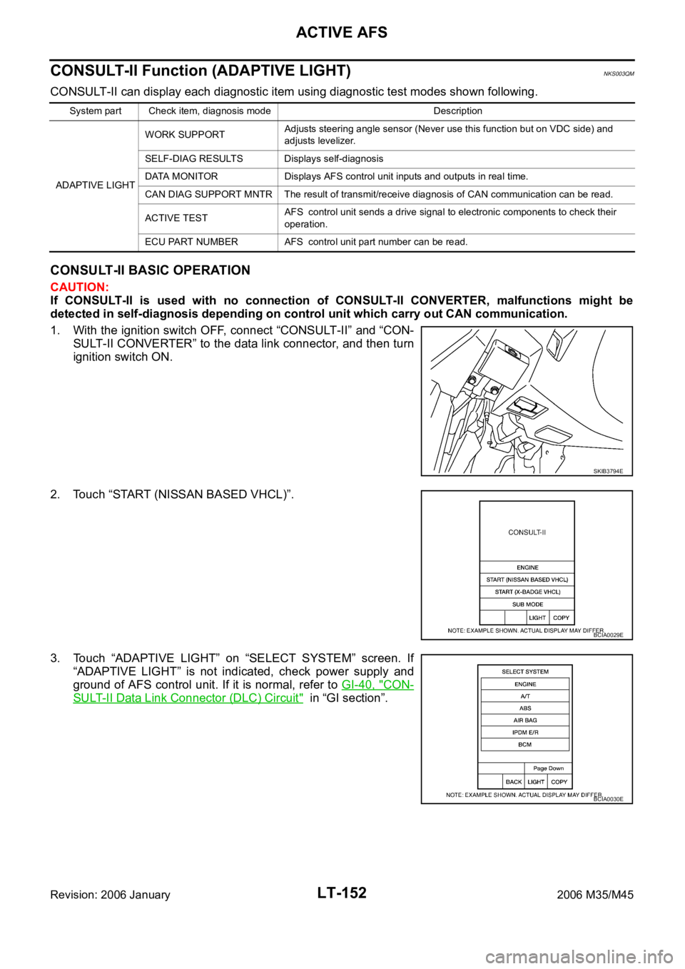
1. With the ignition switch OFF, connect “CONSULT-II” and “CON-
SULT-II CONVERTER” to the data link connector, and then turn
ignition switch ON.
2. Touch “START (NISSAN BASED VHCL)”.
3. Touch “ADAPTIVE LIGHT” on “SELECT SYSTEM” screen. If
“ADAPTIVE LIGHT” is not indicated, check power supply and
ground of AFS control unit. If it is normal, refer to GI-40, "
CON-
SULT-II Data Link Connector (DLC) Circuit" in “GI section”.
System part Check item, diagnosis mode Description
ADAPTIVE LIGHTWORK SUPPORTAdjusts steering angle sensor (Never use this function but on VDC side) and
adjusts levelizer.
SELF-DIAG RESULTS Displays self-diagnosis
DATA MONITOR Displays AFS control unit inputs and outputs in real time.
CAN DIAG SUPPORT MNTR The result of transmit/receive diagnosis of CAN communication can be read.
ACTIVE TESTAFS control unit sends a drive signal to electronic components to check their
operation.
ECU PART NUMBER AFS control unit part number can be read.
SKIB3794E
BCIA0029E
BCIA0030E
Page 4580 of 5621
ACTIVE AFS
LT-153
C
D
E
F
G
H
I
J
L
MA
B
LT
Revision: 2006 January2006 M35/M45
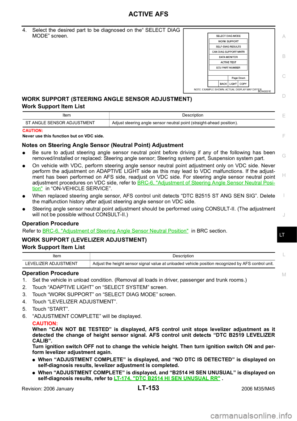
4. Select the desired part to be diagnosed on the“ SELECT DIAG
MODE” screen.
WORK SUPPORT (STEERING ANGLE SENSOR ADJUSTMENT)
Work Support Item List
CAUTION:
Never use this function but on VDC side.
Notes on Steering Angle Sensor (Neutral Point) Adjustment
Be sure to adjust steering angle sensor neutral point before driving if any of the following has been
removed/installed or replaced: Steering angle sensor; Steering system part, Suspension system part.
On vehicle with VDC, perform steering angle sensor neutral point adjustment only on VDC side. Never
perform the adjustment on ADAPTIVE LIGHT side as this may lead to VDC malfunctions. If the adjust-
ment has been performed on AFS side, readjust on VDC side. For steering angle sensor neutral point
adjustment procedures on VDC side, refer to BRC-6, "
Adjustment of Steering Angle Sensor Neutral Posi-
tion" in “ON-VEHICLE SERVICE”.
When replaced steering angle sensor, AFS control unit detects “DTC B2515 ST ANG SEN SIG”. Delete
the malfunction history after adjust steering angle sensor on VDC side.
Steering angle sensor neutral point adjustment should be performed using CONSULT-II. (The adjustment
will not be possible without CONSULT-II.)
Operation Procedure
Refer to BRC-6, "Adjustment of Steering Angle Sensor Neutral Position" in BRC section.
WORK SUPPORT (LEVELIZER ADJUSTMENT)
Work Support Item List
Operation Procedure
1. Set the vehicle in unload condition. (Removal all loads in driver, passenger and trunk rooms.)
2. Touch “ADAPTIVE LIGHT” on “SELECT SYSTEM” screen.
3. Touch “WORK SUPPORT” on “SELECT DIAG MODE” screen.
4. Touch “LEVELIZER ADJUSTMENT”.
5. Touch “START”.
6. “ADJUSTMENT COMPLETE” will be displayed.
CAUTION:
When “CAN NOT BE TESTED” is displayed, AFS control unit stops levelizer adjustment as it
detected the change of height sensor signal. AFS control unit detects “DTC B2519 LEVELIZER
CALIB”.
Turn ignition switch OFF not to change the vehicle height. Then turn ignition switch ON and per-
form levelizer adjustment again.
When “ADJUSTMENT COMPLETE” is displayed, and “NO DTC IS DETECTED” is displayed on
self-diagnosis results, levelizer adjustment is completed.
When “ADJUSTMENT COMPLETE” is displayed, and “B2514 HI SEN UNUSUAL” is displayed on
self-diagnosis results, refer to LT-174, "
DTC B2514 HI SEN UNUSUAL RR" .
BCIA0031E
Item Description
ST ANGLE SENSOR ADJUSTMENT Adjust steering angle sensor neutral point (straight-ahead position).
Item Description
LEVELIZER ADJUSTMENT Adjust the height sensor signal value at unloaded vehicle position recognized by AFS control unit.
Page 4581 of 5621

LT-154
ACTIVE AFS
Revision: 2006 January2006 M35/M45
7. Touch “END”.
8. Turn ignition switch OFF.
SELF-DIAG RESULTS
Operation Procedure
1. Touch “ADAPTIVE LIGHT” on “SELECT SYSTEM” screen.
2. Touch “SELF-DIAG RESULTS” on the “SELECT DIAG MODE” screen.
3. Check display content in self-diagnostic results.
CAUTION:
DTC B2503 and B2504 cannot be detected before the swivel operation. Thus, perform swivel operation
first, and then check the display in self-diagnostic results.
Description of DTC and Solutions after Detection
CONSULT-II can detect DTC (Diagnosis trouble code). The descriptions and solutions of DTC are listed
below.
Details of
error
indication
detected by
CONSULT-
IIConditions of error detectionFail-safe
1. Swivel operation
2. Auto aiming operation
3. AFS OFF indicator operation
4. CancellationReference
CAN
COMM CIR-
CUIT
[U1000]Any of several items below have errors.
TRANSMIT DIAG
Reception from ECM
Reception from unified meter and A/C amp.
Reception from TCM
Reception from steering angle sensor
Reception from IPDM E/R1. Stop the swivel motor RH and
LH when the malfunction
occurred.
2. Stop the aiming motors when the
malfunction occurred.
3. Flash at intervals of approx. 1
second when keeping error state
for 2 seconds or longer.
4. Turn ignition switch OFF.LAN-9,
"TROUBLE
DIAGNOSES
WORK
FLOW" i n L A N
section.
CONTROL
UNIT (CAN)
[U1010]AFS control unit malfunctions.1. Stop the swivel motor RH and
LH when the malfunction
occurred.
2. Stop aiming motors when the
malfunction occurred.
3. Flash at intervals of approx. 1
second when keeping error state
for 2 seconds or longer.
4. Turn ignition switch OFF.Replace
AFS control
unit. LT- 1 9 1