2006 INFINITI M35 sensor
[x] Cancel search: sensorPage 3537 of 5621

GW-18
POWER WINDOW SYSTEM
Revision: 2006 January2006 M35/M45
FAIL-SAFE CONTROL
The encoder signal detects the up / down speed / detection of door glass. If the malfunction is detected to the
encoder signal or the difference between the glass fully closed position (memorized in power window main
switch or power window sub-switch) and the actual glass position is detected, it shifts into the fail-safe control
It is shifts into the fail-safe control, the initialization is not performed and the following function is not activated
Auto up operation
Anti-pinch function
It is shifts into the fail-safe control, performed the initialization to resume normal operation condition.
POWER WINDOW CONTROL BY THE KEY CYLINDER SWITCH
When ignition key switch is OFF, front power window can be opened or closed by turning the key cylinder
switch UNLOCK / LOCK position more than 1.5 second over condition.
Power window can be opened as the door key cylinder is kept fully turning to the UNLOCK position.
Power window can be closed as the door key cylinder is kept fully turning to the LOCK position.
The power window DOWN stops when the following operations are carried out.
While performing open / close the window, power window is stopped at the position as the door key cylin-
der is placed on NEUTRAL.
When the ignition switch is turned ON while the power window DOWN is operated.
DTC Condition
Pulse sensor detects malfunctionDuring the glass opening/closing operation, a pulse signal is continuously
detected for the specified terms or more
Both pulse sensors detect malfunctionDuring the glass opening/closing operation, both pulse signals are not
detected for the specified values or more
Pulse direction malfunctionThe following condition is detected for the specified values or more. The
pulse signal (detected during glass open/close operation) detects the
opposite direction to the driving direction of power window motor.
Glass recognized position malfunction 1During the glass opening/closing operation, the difference between the
glass fully closed position (memorized in power window main switch or
power window sub-switch) and the actual glass position is detected for
the specified values or more.
Glass recognized position malfunction 2During the glass opening/closing operation, a pulse count is detected that
is above the glass full stroke
Glass fully closed position not updated malfunctionContinuously perform the glass open/close operation (with the glass not
fully closed) at the specified value (approx. 10 time) or more
Page 3616 of 5621
![INFINITI M35 2006 Factory Service Manual REVERSE INTERLOCK DOOR MIRROR SYSTEM
GW-97
C
D
E
F
G
H
J
K
L
MA
B
GW
Revision: 2006 January2006 M35/M45
through 10A fuse [No.21, located in the fuse block (J/B)]
to automatic drive positioner control INFINITI M35 2006 Factory Service Manual REVERSE INTERLOCK DOOR MIRROR SYSTEM
GW-97
C
D
E
F
G
H
J
K
L
MA
B
GW
Revision: 2006 January2006 M35/M45
through 10A fuse [No.21, located in the fuse block (J/B)]
to automatic drive positioner control](/manual-img/42/57023/w960_57023-3615.png)
REVERSE INTERLOCK DOOR MIRROR SYSTEM
GW-97
C
D
E
F
G
H
J
K
L
MA
B
GW
Revision: 2006 January2006 M35/M45
through 10A fuse [No.21, located in the fuse block (J/B)]
to automatic drive positioner control unit terminal 34 and
to driver seat control unit terminal 40.
Ground is supplied
to automatic drive positioner control unit terminals 40 and 48.
through body grounds M16 and M70.
to driver seat control unit terminals 32 and 48.
through body grounds B5, B40 and B131.
to door mirror remote control switch terminal 13
through body grounds M16 and M70.
REVERSE INTERLOCK DOOR MIRROR SYSTEM OPERATION
When the ignition switch is in ON position, A/T control device into R position. Then TCM (in A/T assembly)
detects it and sends the A/T shift position signal to the driver seat control unit via DATA LINE (CAN H,
CAN L).
When selecting either left and right changeover switch, the automatic drive position control unit judges
which door mirror is selected according to the voltage of terminals 2 and 18. And then, it sends the signal
to driver seat control unit via communication signal.
When the driver seat control unit receives the A/T shift position signal and changeover switch signal, it
sends the operation signal to the automatic drive positioner control unit using the communication signal so
that the each mirror sensor voltage stays in a specified value.
Door mirror (RH) selected
Supply the power from terminals 14, 15 and 30 to door mirror (RH) terminals 5, 6 and 7 so that the voltage
of terminals 5 and 21 stays in a specified value. Then, adjust the mirror angle.
Door mirror (LH) selected
Supply the power from terminals 16, 31 and 32 to door mirror (LH) terminals 5, 6 and 7 do that the voltage
of terminals 6 and 22 is the specified value. Then, adjust the mirror angle.
CAN Communication System DescriptionNIS00232
CAN (Controller Area Network) is a serial communication line for real time application. It is an on-vehicle mul-
tiplex communication line with high data communication speed and excellent error detection ability. Many elec-
tronic control units are equipped onto a vehicle, and each control unit shares information and links with other
control units during operation (not independent). In CAN communication, control units are connected with 2
communication lines (CAN H line, CAN L line) allowing a high rate of information transmission with less wiring.
Each control unit transmits/receives data but selectively reads required data only.
CAN Communication UnitNIS00233
Refer to LAN-34, "CAN Communication Unit" .
Page 3623 of 5621
GW-104
REVERSE INTERLOCK DOOR MIRROR SYSTEM
Revision: 2006 January2006 M35/M45
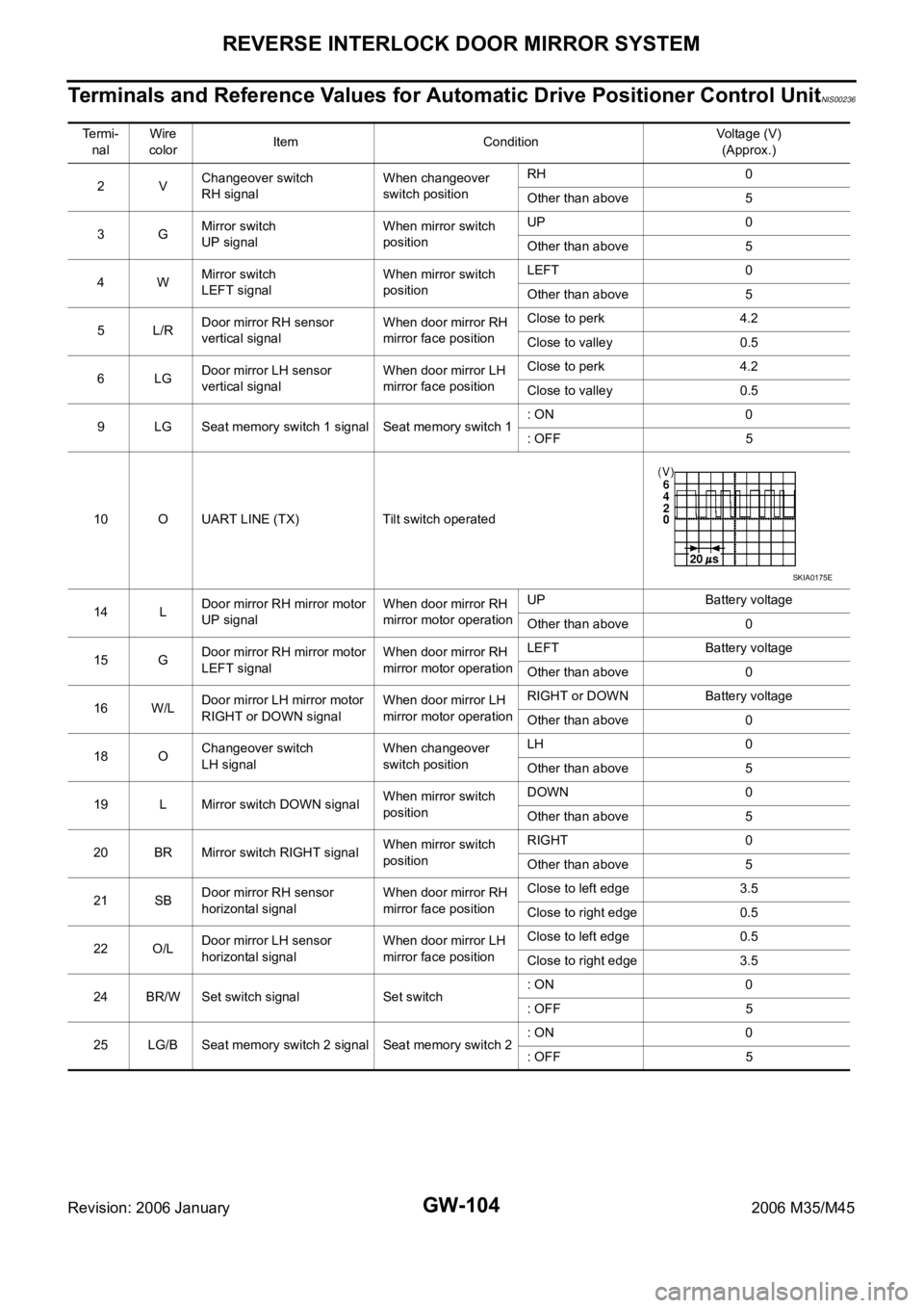
Terminals and Reference Values for Automatic Drive Positioner Control UnitNIS00236
Te r m i -
nalWire
colorItem ConditionVoltage (V)
(Approx.)
2VChangeover switch
RH signalWhen changeover
switch positionRH 0
Other than above 5
3GMirror switch
UP signalWhen mirror switch
positionUP 0
Other than above 5
4WMirror switch
LEFT signalWhen mirror switch
positionLEFT 0
Other than above 5
5L/RDoor mirror RH sensor
vertical signalWhen door mirror RH
mirror face positionClose to perk 4.2
Close to valley 0.5
6LGDoor mirror LH sensor
vertical signalWhen door mirror LH
mirror face positionClose to perk 4.2
Close to valley 0.5
9 LG Seat memory switch 1 signal Seat memory switch 1: ON 0
: OFF 5
10 O UART LINE (TX) Tilt switch operated
14 LDoor mirror RH mirror motor
UP signalWhen door mirror RH
mirror motor operationUP Battery voltage
Other than above 0
15 GDoor mirror RH mirror motor
LEFT signalWhen door mirror RH
mirror motor operationLEFT Battery voltage
Other than above 0
16 W/LDoor mirror LH mirror motor
RIGHT or DOWN signalWhen door mirror LH
mirror motor operationRIGHT or DOWN Battery voltage
Other than above 0
18 OChangeover switch
LH signalWhen changeover
switch positionLH 0
Other than above 5
19 L Mirror switch DOWN signalWhen mirror switch
positionDOWN 0
Other than above 5
20 BR Mirror switch RIGHT signalWhen mirror switch
positionRIGHT 0
Other than above 5
21 SBDoor mirror RH sensor
horizontal signalWhen door mirror RH
mirror face positionClose to left edge 3.5
Close to right edge 0.5
22 O/LDoor mirror LH sensor
horizontal signalWhen door mirror LH
mirror face positionClose to left edge 0.5
Close to right edge 3.5
24 BR/W Set switch signal Set switch: ON 0
: OFF 5
25 LG/B Seat memory switch 2 signal Seat memory switch 2: ON 0
: OFF 5
SKIA0175E
Page 3624 of 5621
REVERSE INTERLOCK DOOR MIRROR SYSTEM
GW-105
C
D
E
F
G
H
J
K
L
MA
B
GW
Revision: 2006 January2006 M35/M45
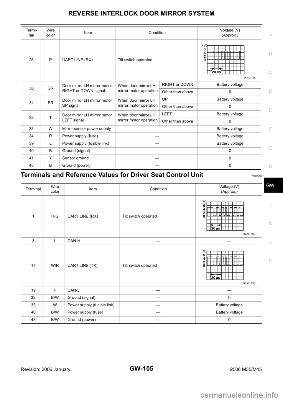
Terminals and Reference Values for Driver Seat Control UnitNIS00237
26 P UART LINE (RX) Tilt switch operated
30 GRDoor mirror LH mirror motor
RIGHT or DOWN signalWhen door mirror LH
mirror motor operationRIGHT or DOWN Battery voltage
Other than above 0
31 BRDoor mirror LH mirror motor
UP signalWhen door mirror LH
mirror motor operationUP Battery voltage
Other than above 0
32 TDoor mirror LH mirror motor
LEFT signalWhen door mirror LH
mirror motor operationLEFT Battery voltage
Other than above 0
33 W Mirror sensor power supply — Battery voltage
34 R Power supply (fuse) — Battery voltage
39 L Power supply (fusible link) — Battery voltage
40 B Ground (signal) — 0
41 Y Sensor ground — 0
48 B Ground (power) — 0 Termi-
nalWire
colorItem ConditionVoltage (V)
(Approx.)
SKIA0175E
Terminal Wire
colorItem ConditionVoltage (V)
(Approx.)
1 R/G UART LINE (RX) Tilt switch operated
3 L CAN-H — —
17 W/R UART LINE (TX) Tilt switch operated
19 P CAN-L — —
32 B/W Ground (signal) — 0
33 W Power supply (fusible link) — Battery voltage
40 B/W Power supply (fuse) — Battery voltage
48 B/W Ground (power) — 0
SKIA0175E
SKIA0175E
Page 3626 of 5621
REVERSE INTERLOCK DOOR MIRROR SYSTEM
GW-107
C
D
E
F
G
H
J
K
L
MA
B
GW
Revision: 2006 January2006 M35/M45
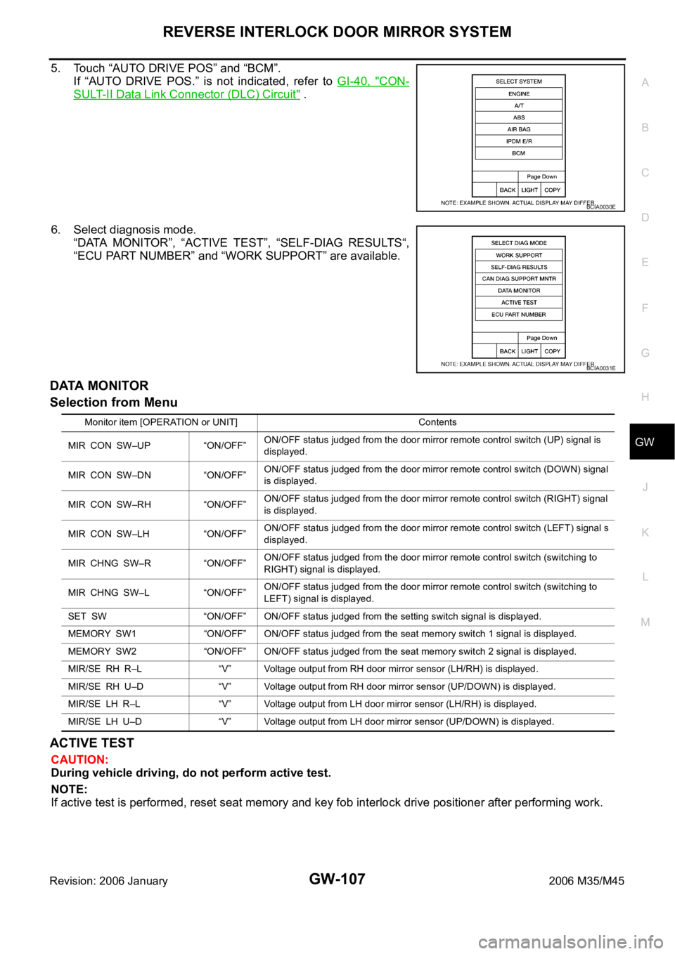
5. Touch “AUTO DRIVE POS” and “BCM”.
If “AUTO DRIVE POS.” is not indicated, refer to GI-40, "
CON-
SULT-II Data Link Connector (DLC) Circuit" .
6. Select diagnosis mode.
“DATA MONITOR”, “ACTIVE TEST”, “SELF-DIAG RESULTS“,
“ECU PART NUMBER” and “WORK SUPPORT” are available.
DATA MONITOR
Selection from Menu
ACTIVE TEST
CAUTION:
During vehicle driving, do not perform active test.
NOTE:
If active test is performed, reset seat memory and key fob interlock drive positioner after performing work.
BCIA0030E
BCIA0031E
Monitor item [OPERATION or UNIT] Contents
MIR CON SW–UP “ON/OFF”ON/OFF status judged from the door mirror remote control switch (UP) signal is
displayed.
MIR CON SW–DN “ON/OFF”ON/OFF status judged from the door mirror remote control switch (DOWN) signal
is displayed.
MIR CON SW–RH “ON/OFF”ON/OFF status judged from the door mirror remote control switch (RIGHT) signal
is displayed.
MIR CON SW–LH “ON/OFF”ON/OFF status judged from the door mirror remote control switch (LEFT) signal s
displayed.
MIR CHNG SW–R “ON/OFF”ON/OFF status judged from the door mirror remote control switch (switching to
RIGHT) signal is displayed.
MIR CHNG SW–L “ON/OFF”ON/OFF status judged from the door mirror remote control switch (switching to
LEFT) signal is displayed.
SET SW “ON/OFF” ON/OFF status judged from the setting switch signal is displayed.
MEMORY SW1 “ON/OFF” ON/OFF status judged from the seat memory switch 1 signal is displayed.
MEMORY SW2 “ON/OFF” ON/OFF status judged from the seat memory switch 2 signal is displayed.
MIR/SE RH R–L “V” Voltage output from RH door mirror sensor (LH/RH) is displayed.
MIR/SE RH U–D “V” Voltage output from RH door mirror sensor (UP/DOWN) is displayed.
MIR/SE LH R–L “V” Voltage output from LH door mirror sensor (LH/RH) is displayed.
MIR/SE LH U–D “V” Voltage output from LH door mirror sensor (UP/DOWN) is displayed.
Page 3627 of 5621
GW-108
REVERSE INTERLOCK DOOR MIRROR SYSTEM
Revision: 2006 January2006 M35/M45
Display Item List
Work Flow NIS00239
1. Check the symptom and customer's requests.
2. Understand the system description. Refer to GW-96, "
System Description" .
3. According to the trouble diagnosis chart, repair or replace the cause of the malfunction. Refer to GW-109,
"Check Changeover Switch Circuit" .
4. Does reverse interlock door mirror system operate normally?
Yes , GO TO 5.
No, GO TO 3.
5. INSPECTION END
Symptom ChartNIS0023A
Test item Description
MIRROR MOTOR RHThe RH mirror motor moves the mirror UP/DOWN and LEFT/RIGHT by receiving the drive
signal.
MIRROR MOTOR LHThe LH mirror motor moves the mirror UP/DOWN and LEFT/RIGHT by receiving the drive
signal.
Symptom Diagnoses / service procedureReference
page
Reverse interlock door mirror does not operate.1. Check seat set switch circuitSE-80
2. Check changeover switch circuitGW-109
3. Check mirror switch circuitGW-111
4. Check A/T control device R position signal circuitGW-119
5. Check mirror motor circuitGW-113
6. Check mirror sensor circuitGW-116
7. Replace automatic drive positioner control unitSE-11
At reverse interlock door mirror system operation, mir-
ror angle is not in the setting position
After finishing the reverse interlock door mirror system.
Operation, mirror angle does not return to the original
position1. Check mirror sensor circuitGW-1162. Check A/T control device R position signal circuitGW-119
3. Replace automatic drive positioner control unitSE-11
Page 3635 of 5621
GW-116
REVERSE INTERLOCK DOOR MIRROR SYSTEM
Revision: 2006 January2006 M35/M45
Check Mirror Sensor Circuit Check NIS0023E
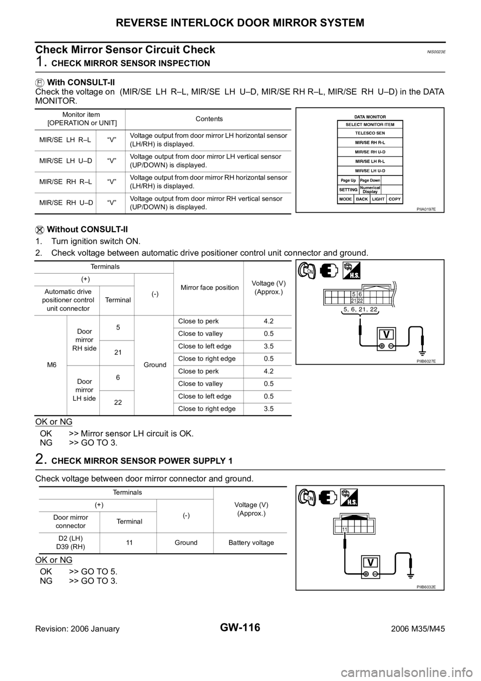
1. CHECK MIRROR SENSOR INSPECTION
With CONSULT-II
Check the voltage on (MIR/SE LH R–L, MIR/SE LH U–D, MIR/SE RH R–L, MIR/SE RH U–D) in the DATA
MONITOR.
Without CONSULT-II
1. Turn ignition switch ON.
2. Check voltage between automatic drive positioner control unit connector and ground.
OK or NG
OK >> Mirror sensor LH circuit is OK.
NG >> GO TO 3.
2. CHECK MIRROR SENSOR POWER SUPPLY 1
Check voltage between door mirror connector and ground.
OK or NG
OK >> GO TO 5.
NG >> GO TO 3.
Monitor item
[OPERATION or UNIT]Contents
MIR/SE LH R–L “V”Voltage output from door mirror LH horizontal sensor
(LH/RH) is displayed.
MIR/SE LH U–D “V”Voltage output from door mirror LH vertical sensor
(UP/DOWN) is displayed.
MIR/SE RH R–L “V”Voltage output from door mirror RH horizontal sensor
(LH/RH) is displayed.
MIR/SE RH U–D “V”Voltage output from door mirror RH vertical sensor
(UP/DOWN) is displayed.
PIIA0197E
Terminals
Mirror face positionVoltage (V)
(Approx.) (+)
(-) Automatic drive
positioner control
unit connectorTerminal
M6Door
mirror
RH side5
GroundClose to perk 4.2
Close to valley 0.5
21Close to left edge 3.5
Close to right edge 0.5
Door
mirror
LH side6Close to perk 4.2
Close to valley 0.5
22Close to left edge 0.5
Close to right edge 3.5
PIIB6027E
Terminals
Voltage (V)
(Approx.) (+)
(-)
Door mirror
connectorTe r m i n a l
D2 (LH)
D39 (RH)11 Ground Battery voltage
PIIB6032E
Page 3636 of 5621
REVERSE INTERLOCK DOOR MIRROR SYSTEM
GW-117
C
D
E
F
G
H
J
K
L
MA
B
GW
Revision: 2006 January2006 M35/M45
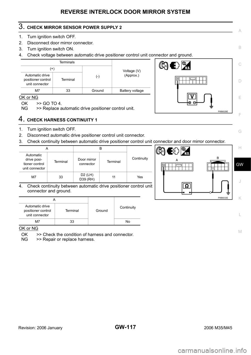
3. CHECK MIRROR SENSOR POWER SUPPLY 2
1. Turn ignition switch OFF.
2. Disconnect door mirror connector.
3. Turn ignition switch ON.
4. Check voltage between automatic drive positioner control unit connector and ground.
OK or NG
OK >> GO TO 4.
NG >> Replace automatic drive positioner control unit.
4. CHECK HARNESS CONTINUITY 1
1. Turn ignition switch OFF.
2. Disconnect automatic drive positioner control unit connector.
3. Check continuity between automatic drive positioner control unit connector and door mirror connector.
4. Check continuity between automatic drive positioner control unit
connector and ground.
OK or NG
OK >> Check the condition of harness and connector.
NG >> Repair or replace harness.
Terminals
Voltage (V)
(Approx.) (+)
(-) Automatic drive
positioner control
unit connectorTerminal
M7 33 Ground Battery voltage
PIIB6028E
AB
Continuity Automatic
drive posi-
tioner control
unit connectorTerminalDoor mirror
connectorTerminal
M7 33D2 (LH)
D39 (RH)11 Ye s
A
GroundContinuity Automatic drive
positioner control
unit connectorTerminal
M7 33 No
PIIB6033E