2006 INFINITI M35 stall
[x] Cancel search: stallPage 5006 of 5621
WHEEL HUB
RAX-7
C
E
F
G
H
I
J
K
L
MA
B
RAX
Revision: 2006 January2006 M35/M45
INSTALLATION
Wheel Hub and Bearing Assembly
Installation is the reverse order of removal. For tightening torque refer to RAX-5, "COMPONENT" .
CAUTION:
Do not reuse non-reusable parts.
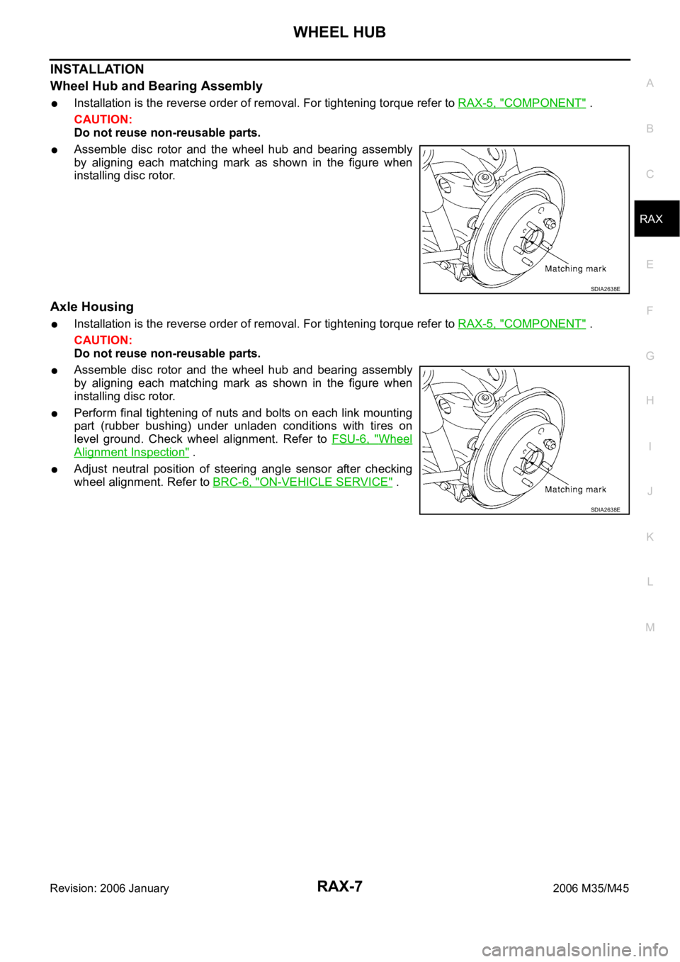
Assemble disc rotor and the wheel hub and bearing assembly
by aligning each matching mark as shown in the figure when
installing disc rotor.
Axle Housing
Installation is the reverse order of removal. For tightening torque refer to RAX-5, "COMPONENT" .
CAUTION:
Do not reuse non-reusable parts.
Assemble disc rotor and the wheel hub and bearing assembly
by aligning each matching mark as shown in the figure when
installing disc rotor.
Perform final tightening of nuts and bolts on each link mounting
part (rubber bushing) under unladen conditions with tires on
level ground. Check wheel alignment. Refer to FSU-6, "
Wheel
Alignment Inspection" .
Adjust neutral position of steering angle sensor after checking
wheel alignment. Refer to BRC-6, "
ON-VEHICLE SERVICE" .
SDIA2638E
SDIA2638E
Page 5007 of 5621
RAX-8
REAR DRIVE SHAFT
Revision: 2006 January2006 M35/M45
REAR DRIVE SHAFTPFP:39600
Removal and InstallationNDS000FS
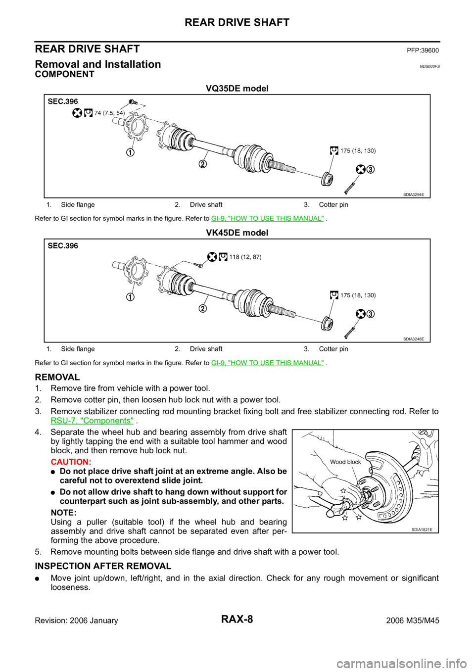
COMPONENT
VQ35DE model
Refer to GI section for symbol marks in the figure. Refer to GI-9, "HOW TO USE THIS MANUAL" .
VK45DE model
Refer to GI section for symbol marks in the figure. Refer to GI-9, "HOW TO USE THIS MANUAL" .
REMOVAL
1. Remove tire from vehicle with a power tool.
2. Remove cotter pin, then loosen hub lock nut with a power tool.
3. Remove stabilizer connecting rod mounting bracket fixing bolt and free stabilizer connecting rod. Refer to
RSU-7, "
Components" .
4. Separate the wheel hub and bearing assembly from drive shaft
by lightly tapping the end with a suitable tool hammer and wood
block, and then remove hub lock nut.
CAUTION:
Do not place drive shaft joint at an extreme angle. Also be
careful not to overextend slide joint.
Do not allow drive shaft to hang down without support for
counterpart such as joint sub-assembly, and other parts.
NOTE:
Using a puller (suitable tool) if the wheel hub and bearing
assembly and drive shaft cannot be separated even after per-
forming the above procedure.
5. Remove mounting bolts between side flange and drive shaft with a power tool.
INSPECTION AFTER REMOVAL
Move joint up/down, left/right, and in the axial direction. Check for any rough movement or significant
looseness.
SDIA3294E
1. Side flange 2. Drive shaft 3. Cotter pin
SDIA3248E
1. Side flange 2. Drive shaft 3. Cotter pin
SDIA1821E
Page 5008 of 5621
REAR DRIVE SHAFT
RAX-9
C
E
F
G
H
I
J
K
L
MA
B
RAX
Revision: 2006 January2006 M35/M45
Check boot for cracks or other damage, and also for grease
leakage.
If a malfunction is found, disassemble drive shaft, and then
replace with new one.
INSTALLATION
Installation is the reverse order of removal. For tightening torque. Refer to RAX-8, "COMPONENT" .
CAUTION:
Do not reuse non-reusable parts.
Disassembly and AssemblyNDS000FT
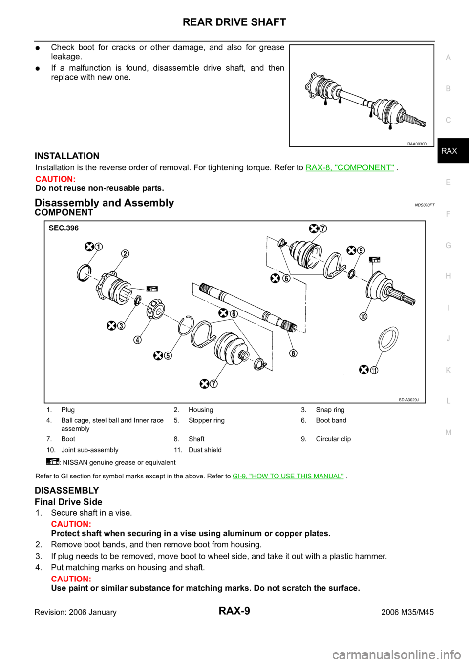
COMPONENT
Refer to GI section for symbol marks except in the above. Refer to GI-9, "HOW TO USE THIS MANUAL" .
DISASSEMBLY
Final Drive Side
1. Secure shaft in a vise.
CAUTION:
Protect shaft when securing in a vise using aluminum or copper plates.
2. Remove boot bands, and then remove boot from housing.
3. If plug needs to be removed, move boot to wheel side, and take it out with a plastic hammer.
4. Put matching marks on housing and shaft.
CAUTION:
Use paint or similar substance for matching marks. Do not scratch the surface.
RAA0030D
1. Plug 2. Housing 3. Snap ring
4. Ball cage, steel ball and Inner race
assembly5. Stopper ring 6. Boot band
7. Boot 8. Shaft 9. Circular clip
10. Joint sub-assembly 11. Dust shield
: NISSAN genuine grease or equivalent
SDIA3029J
Page 5010 of 5621
REAR DRIVE SHAFT
RAX-11
C
E
F
G
H
I
J
K
L
MA
B
RAX
Revision: 2006 January2006 M35/M45
CAUTION:
If there are any irregular conditions of joint sub-assembly components, replace the entire joint sub-
assembly.
Final Drive Side
Make sure there are compression scars, cracks, fractures or unusual wear of ball rolling surface.
Make sure there is no damage to shaft screws.
Make sure there is no deformation of boot installation parts.
Ball Cage
Make sure there are compression scars, cracks, fractures of sliding surface.
Steel Ball
Make sure there are compression scars, cracks, fractures or unusual wear.
Inner Race
Check ball sliding surface for compression scars, cracks or fractures.
Make sure there is no damage to serrated part.
CAUTION:
If there are any irregular conditions in the component, replace with a new set of housing and the
ball cage, steel ball and inner race assembly.
ASSEMBLY
Final Drive Side
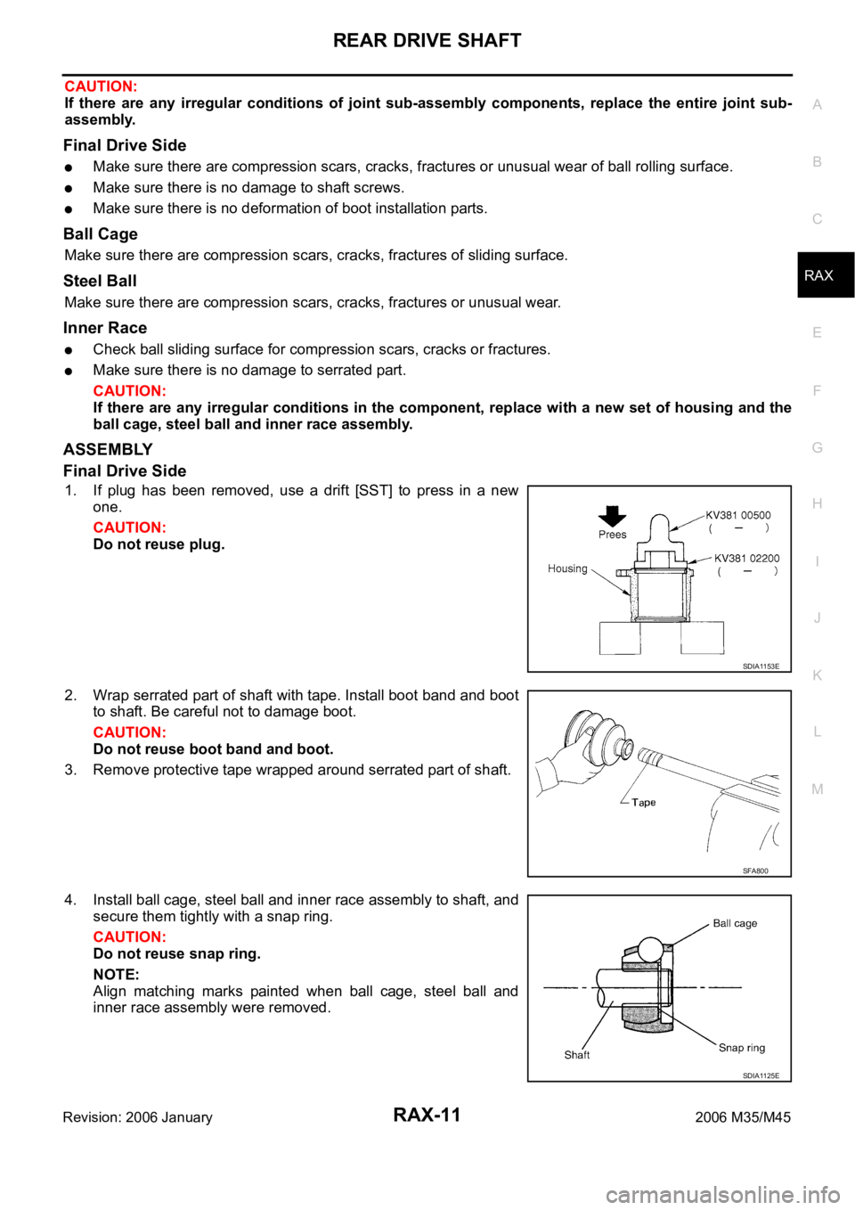
1. If plug has been removed, use a drift [SST] to press in a new
one.
CAUTION:
Do not reuse plug.
2. Wrap serrated part of shaft with tape. Install boot band and boot
to shaft. Be careful not to damage boot.
CAUTION:
Do not reuse boot band and boot.
3. Remove protective tape wrapped around serrated part of shaft.
4. Install ball cage, steel ball and inner race assembly to shaft, and
secure them tightly with a snap ring.
CAUTION:
Do not reuse snap ring.
NOTE:
Align matching marks painted when ball cage, steel ball and
inner race assembly were removed.
SDIA1153E
SFA800
SDIA1125E
Page 5011 of 5621
RAX-12
REAR DRIVE SHAFT
Revision: 2006 January2006 M35/M45
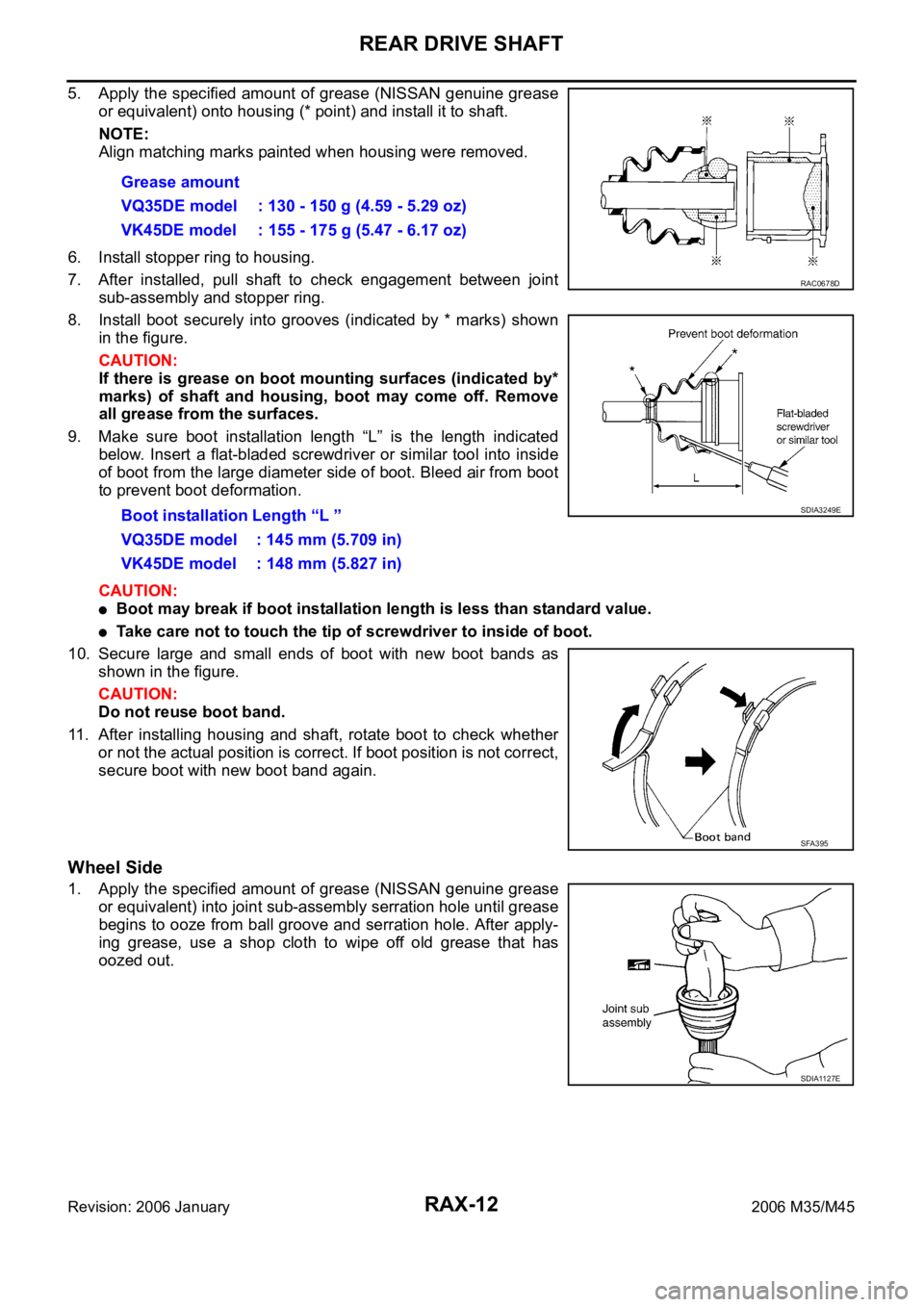
5. Apply the specified amount of grease (NISSAN genuine grease
or equivalent) onto housing (* point) and install it to shaft.
NOTE:
Align matching marks painted when housing were removed.
6. Install stopper ring to housing.
7. After installed, pull shaft to check engagement between joint
sub-assembly and stopper ring.
8. Install boot securely into grooves (indicated by * marks) shown
in the figure.
CAUTION:
If there is grease on boot mounting surfaces (indicated by*
marks) of shaft and housing, boot may come off. Remove
all grease from the surfaces.
9. Make sure boot installation length “L” is the length indicated
below. Insert a flat-bladed screwdriver or similar tool into inside
of boot from the large diameter side of boot. Bleed air from boot
to prevent boot deformation.
CAUTION:
Boot may break if boot installation length is less than standard value.
Take care not to touch the tip of screwdriver to inside of boot.
10. Secure large and small ends of boot with new boot bands as
shown in the figure.
CAUTION:
Do not reuse boot band.
11. After installing housing and shaft, rotate boot to check whether
or not the actual position is correct. If boot position is not correct,
secure boot with new boot band again.
Wheel Side
1. Apply the specified amount of grease (NISSAN genuine grease
or equivalent) into joint sub-assembly serration hole until grease
begins to ooze from ball groove and serration hole. After apply-
ing grease, use a shop cloth to wipe off old grease that has
oozed out.Grease amount
VQ35DE model : 130 - 150 g (4.59 - 5.29 oz)
VK45DE model : 155 - 175 g (5.47 - 6.17 oz)
Boot installation Length “L ”
VQ35DE model : 145 mm (5.709 in)
VK45DE model : 148 mm (5.827 in)
RAC0678D
SDIA3249E
SFA395
SDIA1127E
Page 5012 of 5621
REAR DRIVE SHAFT
RAX-13
C
E
F
G
H
I
J
K
L
MA
B
RAX
Revision: 2006 January2006 M35/M45
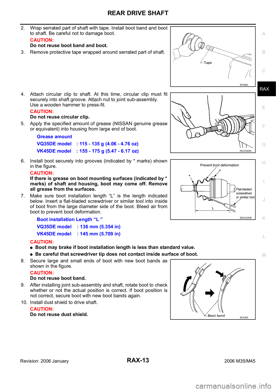
2. Wrap serrated part of shaft with tape. Install boot band and boot
to shaft. Be careful not to damage boot.
CAUTION:
Do not reuse boot band and boot.
3. Remove protective tape wrapped around serrated part of shaft.
4. Attach circular clip to shaft. At this time, circular clip must fit
securely into shaft groove. Attach nut to joint sub-assembly.
Use a wooden hammer to press-fit.
CAUTION:
Do not reuse circular clip.
5. Apply the specified amount of grease (NISSAN genuine grease
or equivalent) into housing from large end of boot.
6. Install boot securely into grooves (indicated by * marks) shown
in the figure.
CAUTION:
If there is grease on boot mounting surfaces (indicated by *
marks) of shaft and housing, boot may come off. Remove
all grease from the surfaces.
7. Make sure boot installation length “L” is the length indicated
below. Insert a flat-bladed screwdriver or similar tool into inside
of boot from the large diameter side of the boot. Bleed air from
boot to prevent boot deformation.
CAUTION:
Boot may brake if boot installation length is less than standard value.
Be careful that screwdriver tip does not contact inside surface of boot.
8. Secure large and small ends of boot with new boot bands as
shown in the figure.
CAUTION:
Do not reuse boot band.
9. After installing joint sub-assembly and shaft, rotate boot to check
whether or not the actual position is correct. If boot position is
not correct, secure boot with new boot bands again.
10. Install dust shield to drive shaft.
CAUTION:
Do not reuse dust shield.
SFA800
Grease amount
VQ35DE model : 115 - 135 g (4.06 - 4.76 oz)
VK45DE model : 155 - 175 g (5.47 - 6.17 oz)
RAC0049D
Boot installation Length “L ”
VQ35DE model : 136 mm (5.354 in)
VK45DE model : 145 mm (5.709 in)SDIA3250E
SFA395
Page 5013 of 5621

RAX-14
SERVICE DATA
Revision: 2006 January2006 M35/M45
SERVICE DATAPFP:00030
Wheel BearingNDS000FU
Drive ShaftNDS000FV
Axial end play 0.05 mm (0.002 in) or less
Joint typeWheel side Final drive side
VQ35DE model VK45DE model VQ35DE model VK45DE model
Grease quantity115 - 135 g
(4.06 - 4.76 oz)155 - 175 g
(5.47 - 6.17 oz)130 - 150 g
(4.59 - 5.29 oz)155 - 175 g
(5.47 - 6.17 oz)
Boots installed length 136 mm (5.354 in) 145 mm (5.709 in) 145 mm (5.709 in) 148 mm (5.827 in)
Page 5014 of 5621
RF-1
ROOF
I BODY
CONTENTS
C
D
E
F
G
H
J
K
L
M
SECTION RF
A
B
RF
Revision: 2006 January2006 M35/M45
ROOF
PRECAUTIONS .......................................................... 2
Precautions for Supplemental Restraint System
(SRS) “AIR BAG” and “SEAT BELT PRE-TEN-
SIONER” .................................................................. 2
Precautions .............................................................. 2
PREPARATION ........................................................... 3
Special Service Tools ............................................... 3
Commercial Service Tools ........................................ 3
SQUEAK AND RATTLE TROUBLE DIAGNOSES ..... 4
Work Flow ................................................................ 4
CUSTOMER INTERVIEW ..................................... 4
DUPLICATE THE NOISE AND TEST DRIVE ....... 5
CHECK RELATED SERVICE BULLETINS ........... 5
LOCATE THE NOISE AND IDENTIFY THE
ROOT CAUSE ...................................................... 5
REPAIR THE CAUSE ........................................... 5
CONFIRM THE REPAIR ....................................... 6
Generic Squeak and Rattle Troubleshooting ........... 6
INSTRUMENT PANEL .......................................... 6
CENTER CONSOLE ............................................. 6
DOORS ................................................................. 6
TRUNK .................................................................. 7
SUNROOF/HEADLINING ..................................... 7
SEATS ................................................................... 7
UNDERHOOD ....................................................... 7
Diagnostic Worksheet .............................................. 8
SUNROOF ................................................................ 10
Component Parts and Harness Connector Location ... 10
System Description ................................................. 11
TILT UP / SLIDE CLOSE OPERATION ................ 11TILT DOWN / SLIDE OPEN OPERATION .......... 11
AUTO OPERATION ............................................. 11
RETAINED POWER OPERATION ...................... 11
ANTI-PINCH FUNCTION .................................... 12
INITIALIZATION PROCEDURE .......................... 12
Wiring Diagram — SROOF — ................................ 13
Terminals and Reference Value for BCM ............... 15
Terminals and Reference Value for Sunroof Motor
Assembly ................................................................ 15
CONSULT-II Function (BCM) ................................. 16
ACTIVE TEST ..................................................... 17
WORK SUPPORT ............................................... 17
DATE MONITOR ................................................. 17
Work Flow ............................................................... 18
Diagnosis Symptom Chart ...................................... 18
BCM Power Supply and Ground Circuit Check ...... 18
Sunroof Motor Assembly Power Supply and Ground
Circuit Check .......................................................... 19
Sunroof Switch Check .........................................
... 21
Door Switch Check ..............................................
... 23
Fitting Adjustment ................................................... 25
RID WEATHERSTRIP OVERLAP ADJUST-
MENT AND SURFACE MISMATCH ADJUST-
MENT .................................................................. 25
Removal and Installation ........................................ 25
SUNROOF UNIT ................................................. 27
Disassembly and Assembly .................................... 28
DISASSEMBLY ................................................... 29
ASSEMBLY ......................................................... 29