Page 4986 of 5621
POWER STEERING OIL PUMP
PS-33
C
D
E
F
H
I
J
K
L
MA
B
PS
Revision: 2006 January2006 M35/M45
When installing rotor, turn mark face on rotor to body assem-
bly.
7. Install vane to rotor so that arc of vane faces cam ring side.
8. Check if drive shaft turns smoothly.
9. Install gasket to body assembly.
10. Install rear cover to body assembly, and then tighten mounting
bolts to the specified torque.
11. Install pulley and washer to drive shaft, and then tighten lock nut
at the specified torque.
12. Install spring, flow control valve and O-ring to body assembly,
and then tighten connector bolt to the specified torque.
13. Install O-ring, joint and copper washer to connector bolt, and
then tighten lock nut to the specified torque.
14. Apply power steering fluid to O-ring, and then install O-ring to
body assembly.
15. Install suction pipe to body assembly.
SGIA0874E
SGIA0613E
SGIA0425E
Page 4989 of 5621

PS-36
POWER STEERING OIL PUMP
Revision: 2006 January2006 M35/M45
ASSEMBLY
NOTE:
Secure oil pump in a vise if necessary.
CAUTION:
Use copper plates when securing in a vise.
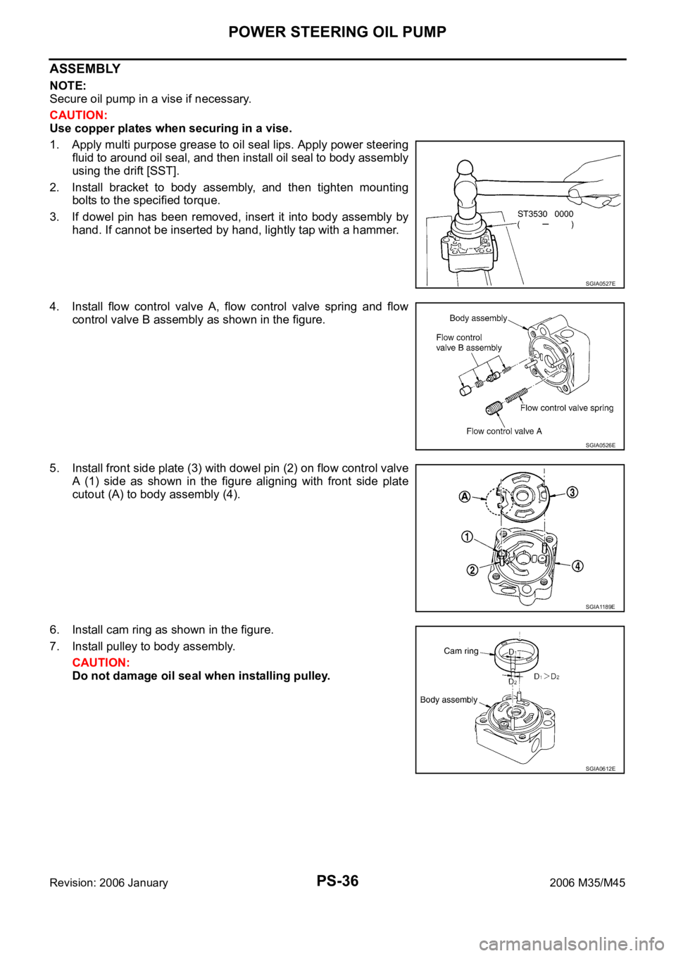
1. Apply multi purpose grease to oil seal lips. Apply power steering
fluid to around oil seal, and then install oil seal to body assembly
using the drift [SST].
2. Install bracket to body assembly, and then tighten mounting
bolts to the specified torque.
3. If dowel pin has been removed, insert it into body assembly by
hand. If cannot be inserted by hand, lightly tap with a hammer.
4. Install flow control valve A, flow control valve spring and flow
control valve B assembly as shown in the figure.
5. Install front side plate (3) with dowel pin (2) on flow control valve
A (1) side as shown in the figure aligning with front side plate
cutout (A) to body assembly (4).
6. Install cam ring as shown in the figure.
7. Install pulley to body assembly.
CAUTION:
Do not damage oil seal when installing pulley.
SGIA0527E
SGIA0526E
SGIA1189E
SGIA0612E
Page 4990 of 5621

POWER STEERING OIL PUMP
PS-37
C
D
E
F
H
I
J
K
L
MA
B
PS
Revision: 2006 January2006 M35/M45
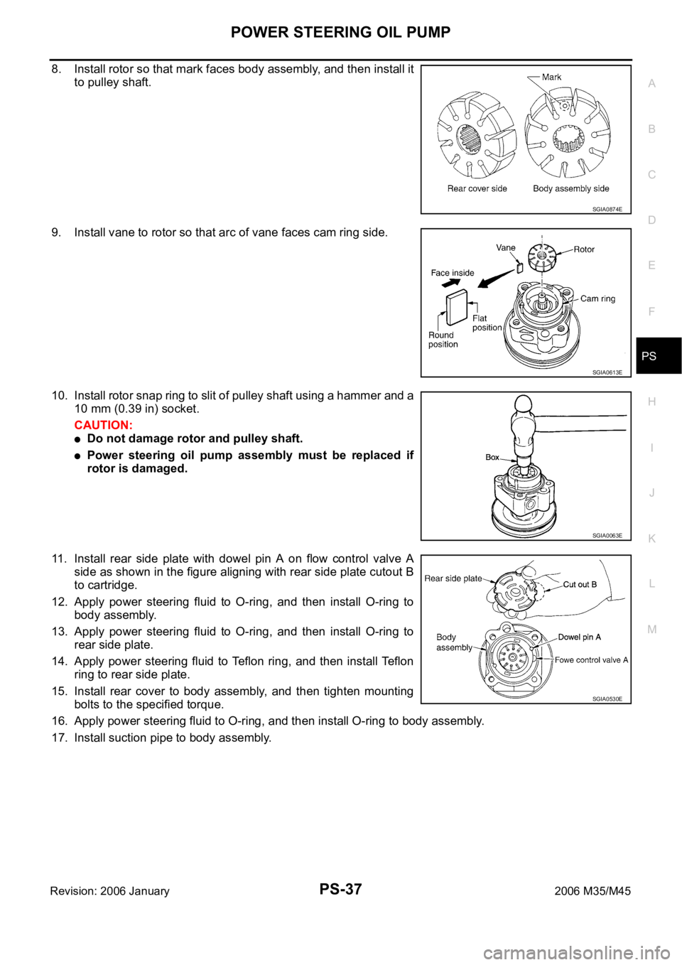
8. Install rotor so that mark faces body assembly, and then install it
to pulley shaft.
9. Install vane to rotor so that arc of vane faces cam ring side.
10. Install rotor snap ring to slit of pulley shaft using a hammer and a
10 mm (0.39 in) socket.
CAUTION:
Do not damage rotor and pulley shaft.
Power steering oil pump assembly must be replaced if
rotor is damaged.
11. Install rear side plate with dowel pin A on flow control valve A
side as shown in the figure aligning with rear side plate cutout B
to cartridge.
12. Apply power steering fluid to O-ring, and then install O-ring to
body assembly.
13. Apply power steering fluid to O-ring, and then install O-ring to
rear side plate.
14. Apply power steering fluid to Teflon ring, and then install Te f l o n
ring to rear side plate.
15. Install rear cover to body assembly, and then tighten mounting
bolts to the specified torque.
16. Apply power steering fluid to O-ring, and then install O-ring to body assembly.
17. Install suction pipe to body assembly.
SGIA0874E
SGIA0613E
SGIA0063E
SGIA0530E
Page 4996 of 5621
HYDRAULIC LINE
PS-43
C
D
E
F
H
I
J
K
L
MA
B
PS
Revision: 2006 January2006 M35/M45
Removal and InstallationNGS000DL
Insert hose securely until it contacts tube spool.
CAUTION:
Do not apply fluid.
Install eye-bolt with eye-joint (assembled to high-pressure hose)
protrusion facing with pump side cutout, and then tighten it to
the specified torque after tightening by hand.
Refer to GI-11, "Components" , and the followings for the symbols in the figure.
: Apply power steering fluid.
SGIA0514E
SGIA0515E
Page 5000 of 5621

RAX-1
REAR AXLE
D DRIVELINE/AXLE
CONTENTS
C
E
F
G
H
I
J
K
L
M
SECTION RAX
A
B
RAX
Revision: 2006 January2006 M35/M45
REAR AXLE
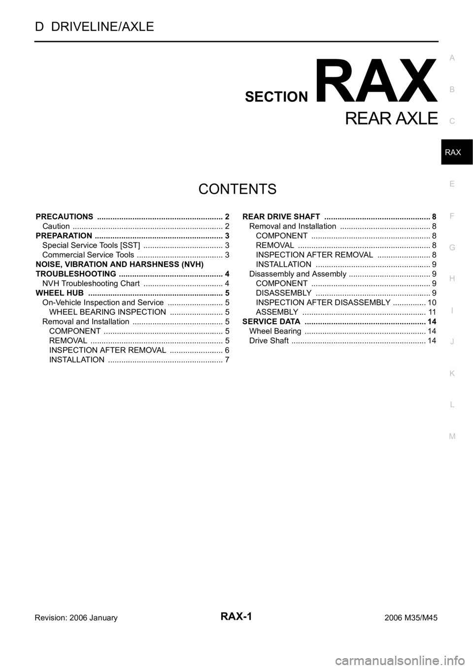
PRECAUTIONS .......................................................... 2
Caution ..................................................................... 2
PREPARATION ........................................................... 3
Special Service Tools [SST] ..................................... 3
Commercial Service Tools ........................................ 3
NOISE, VIBRATION AND HARSHNESS (NVH)
TROUBLESHOOTING ................................................ 4
NVH Troubleshooting Chart ..................................... 4
WHEEL HUB .............................................................. 5
On-Vehicle Inspection and Service .......................... 5
WHEEL BEARING INSPECTION ......................... 5
Removal and Installation .......................................... 5
COMPONENT ....................................................... 5
REMOVAL ........................................................
..... 5
INSPECTION AFTER REMOVAL ......................... 6
INSTALLATION ..................................................... 7REAR DRIVE SHAFT ................................................. 8
Removal and Installation .......................................... 8
COMPONENT ....................................................... 8
REMOVAL ........................................................
..... 8
INSPECTION AFTER REMOVAL ......................... 8
INSTALLATION ..................................................... 9
Disassembly and Assembly ...................................... 9
COMPONENT ....................................................... 9
DISASSEMBLY ..................................................... 9
INSPECTION AFTER DISASSEMBLY ................ 10
ASSEMBLY ......................................................... 11
SERVICE DATA ........................................................ 14
Wheel Bearing ........................................................ 14
Drive Shaft .............................................................. 14
Page 5002 of 5621
PREPARATION
RAX-3
C
E
F
G
H
I
J
K
L
MA
B
RAX
Revision: 2006 January2006 M35/M45
PREPARATIONPFP:00002
Special Service Tools [SST]NDS000FN
The actual shapes of Kent-Moore tools may differ from those of special service tools illustrated here.
Commercial Service ToolsNDS000FO
Tool number
(Kent-Moore No.)
Tool nameDescription
KV38100500
(—)
Drift
a: 80 mm (3.15 in) dia.
b: 60 mm (2.36 in) dia.Installing drive shaft plug
KV38102200
(—)
Drift
a: 90 mm (3.54 in) dia.
b: 31 mm (1.22 in) dia.Installing drive shaft plug
ZZA0701D
ZZA0920D
Tool nameDescription
Power tool
Removing wheel nuts
Removing brake caliper assembly
Removing suspension links
Removing drive shaft
PBIC0190E
Page 5003 of 5621
RAX-4
NOISE, VIBRATION AND HARSHNESS (NVH) TROUBLESHOOTING
Revision: 2006 January2006 M35/M45
NOISE, VIBRATION AND HARSHNESS (NVH) TROUBLESHOOTINGPFP:00003
NVH Troubleshooting ChartNDS000FP
Use chart below to help you find the cause of the symptom. If necessary, repair or replace these parts.
: ApplicableReference page
—
RAX-10—
RAX-8—
NVH in PR section.
NVH in RFD section.
NVH in RAX and RSU sections.
Refer to REAR AXLE in this chart.
NVH in WT section.
NVH in WT section.
Refer to DRIVE SHAFT in this chart.
NVH in BR section.
NVH in PS section.
Possible cause and SUSPECTED PARTS
Excessive joint angle
Joint sliding resistance
Imbalance
Improper installation, looseness
Parts interference
PROPELLER SHAFT
DIFFERENTIAL
REAR AXLE AND REAR SUSPENSION
REAR AXLE
TIRES
ROAD WHEEL
DRIVE SHAFT
BRAKES
STEERING
SymptomDRIVE
SHAFTNoise
Shake
REAR
AXLENoise
Shake
Vibration
Shimmy
Judder
Poor quality ride or handling
Page 5004 of 5621

WHEEL HUB
RAX-5
C
E
F
G
H
I
J
K
L
MA
B
RAX
Revision: 2006 January2006 M35/M45
WHEEL HUBPFP:43202
On-Vehicle Inspection and ServiceNDS000FQ
Make sure the mounting conditions (looseness, back lash) of each component and component conditions
(wear, damage) are normal.
WHEEL BEARING INSPECTION
Move wheel hub and bearing assembly in the axial direction by hand. Make sure there is no looseness of
wheel bearing.
Rotate wheel hub, and make sure that is no unusual noise or other irregular conditions. If there is any of
irregular conditions, replace wheel hub and bearing assembly.
Removal and InstallationNDS000FR
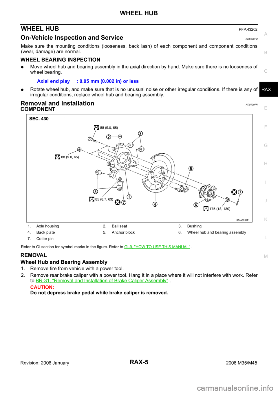
COMPONENT
Refer to GI section for symbol marks in the figure. Refer to GI-9, "HOW TO USE THIS MANUAL" .
REMOVAL
Wheel Hub and Bearing Assembly
1. Remove tire from vehicle with a power tool.
2. Remove rear brake caliper with a power tool. Hang it in a place where it will not interfere with work. Refer
to BR-31, "
Removal and Installation of Brake Caliper Assembly" .
CAUTION:
Do not depress brake pedal while brake caliper is removed. Axial end play : 0.05 mm (0.002 in) or less
1. Axle housing 2. Ball seat 3. Bushing
4. Back plate 5. Anchor block 6. Wheel hub and bearing assembly
7. Cotter pin
SDIA3251E