2006 INFINITI M35 Panel
[x] Cancel search: PanelPage 3520 of 5621
GW-1
GLASSES, WINDOW SYSTEM & MIRRORS
I BODY
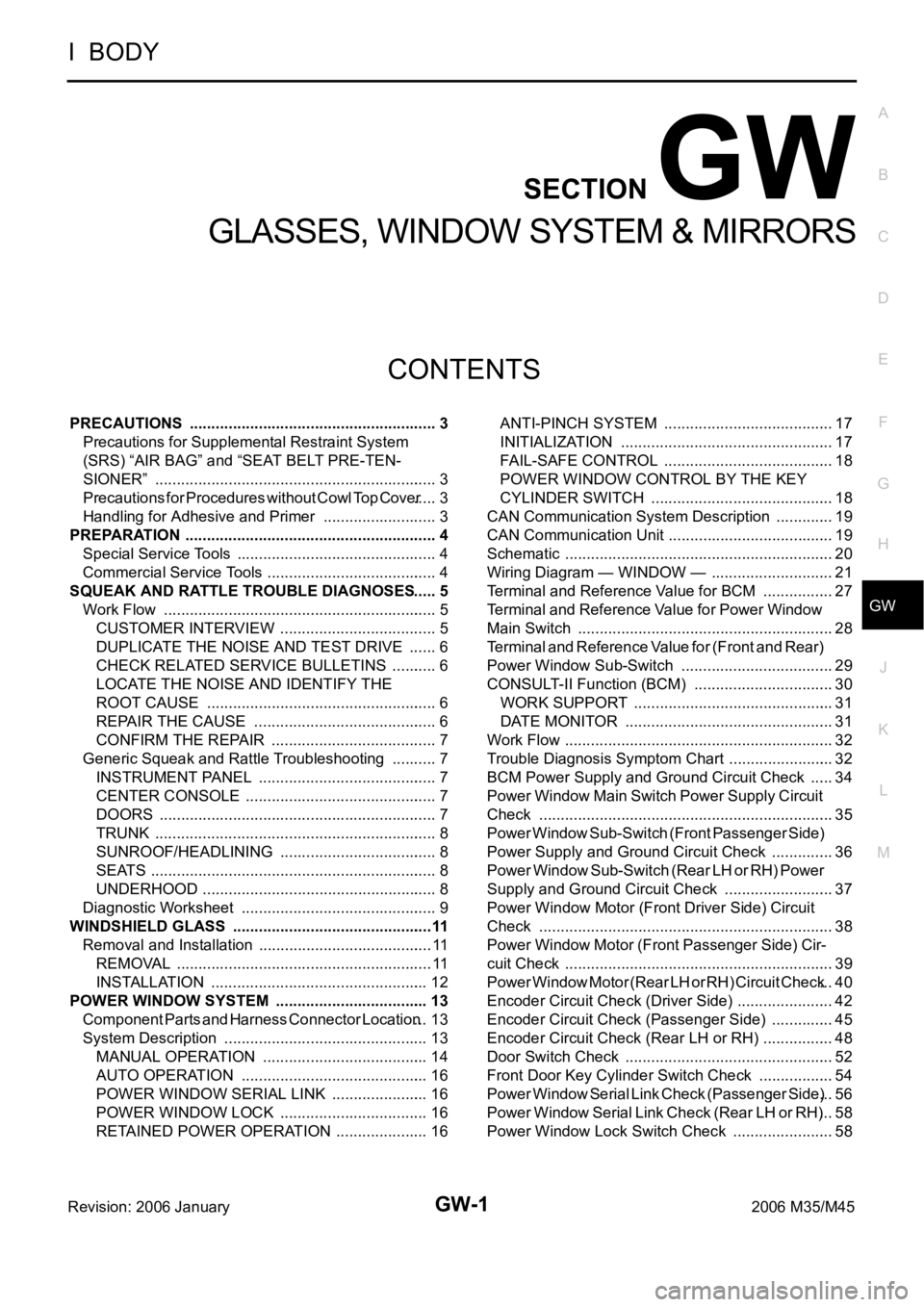
CONTENTS
C
D
E
F
G
H
J
K
L
M
SECTION GW
A
B
GW
Revision: 2006 January2006 M35/M45
GLASSES, WINDOW SYSTEM & MIRRORS
PRECAUTIONS .......................................................... 3
Precautions for Supplemental Restraint System
(SRS) “AIR BAG” and “SEAT BELT PRE-TEN-
SIONER” .................................................................. 3
Precautions for Procedures without Cowl Top Cover ..... 3
Handling for Adhesive and Primer ........................... 3
PREPARATION ........................................................... 4
Special Service Tools ............................................... 4
Commercial Service Tools ........................................ 4
SQUEAK AND RATTLE TROUBLE DIAGNOSES ..... 5
Work Flow ................................................................ 5
CUSTOMER INTERVIEW ..................................... 5
DUPLICATE THE NOISE AND TEST DRIVE ....... 6
CHECK RELATED SERVICE BULLETINS ........... 6
LOCATE THE NOISE AND IDENTIFY THE
ROOT CAUSE ...................................................... 6
REPAIR THE CAUSE ........................................... 6
CONFIRM THE REPAIR ....................................... 7
Generic Squeak and Rattle Troubleshooting ........... 7
INSTRUMENT PANEL .......................................... 7
CENTER CONSOLE ............................................. 7
DOORS ................................................................. 7
TRUNK .................................................................. 8
SUNROOF/HEADLINING ..................................... 8
SEATS ................................................................... 8
UNDERHOOD ....................................................... 8
Diagnostic Worksheet .............................................. 9
WINDSHIELD GLASS ...............................................11
Removal and Installation ......................................... 11
REMOVAL ........................................................
.... 11
INSTALLATION ................................................... 12
POWER WINDOW SYSTEM .................................... 13
Component Parts and Harness Connector Location ... 13
System Description ................................................ 13
MANUAL OPERATION ....................................... 14
AUTO OPERATION ............................................ 16
POWER WINDOW SERIAL LINK ....................... 16
POWER WINDOW LOCK ................................... 16
RETAINED POWER OPERATION ...................... 16ANTI-PINCH SYSTEM ........................................ 17
INITIALIZATION .................................................. 17
FAIL-SAFE CONTROL ........................................ 18
POWER WINDOW CONTROL BY THE KEY
CYLINDER SWITCH ........................................... 18
CAN Communication System Description .............. 19
CAN Communication Unit ....................................... 19
Schematic ............................................................... 20
Wiring Diagram — WINDOW — ............................. 21
Terminal and Reference Value for BCM ................. 27
Terminal and Reference Value for Power Window
Main Switch ............................................................ 28
Terminal and Reference Value for (Front and Rear)
Power Window Sub-Switch .................................... 29
CONSULT-II Function (BCM) ................................. 30
WORK SUPPORT ............................................... 31
DATE MONITOR ................................................. 31
Work Flow ............................................................... 32
Trouble Diagnosis Symptom Chart ......................... 32
BCM Power Supply and Ground Circuit Check ...... 34
Power Window Main Switch Power Supply Circuit
Check ..................................................................... 35
Power Window Sub-Switch (Front Passenger Side)
Power Supply and Ground Circuit Check ............... 36
Power Window Sub-Switch (Rear LH or RH) Power
Supply and Ground Circuit Check .......................... 37
Power Window Motor (Front Driver Side) Circuit
Check ..................................................................... 38
Power Window Motor (Front Passenger Side) Cir-
cuit Check ............................................................... 39
Power Window Motor (Rear LH or RH) Circuit Check ... 40
Encoder Circuit Check (Driver Side) ....................... 42
Encoder Circuit Check (Passenger Side) ............... 45
Encoder Circuit Check (Rear LH or RH) ................. 48
Door Switch Check ..............................................
... 52
Front Door Key Cylinder Switch Check .................. 54
Power Window Serial Link Check (Passenger Side) ... 56
Power Window Serial Link Check (Rear LH or RH) ... 58
Power Window Lock Switch Check ........................ 58
Page 3525 of 5621
GW-6
SQUEAK AND RATTLE TROUBLE DIAGNOSES
Revision: 2006 January2006 M35/M45
DUPLICATE THE NOISE AND TEST DRIVE
If possible, drive the vehicle with the customer until the noise is duplicated. Note any additional information on
the Diagnostic Worksheet regarding the conditions or location of the noise. This information can be used to
duplicate the same conditions when you confirm the repair.
If the noise can be duplicated easily during the test drive, to help identify the source of the noise, try to dupli-
cate the noise with the vehicle stopped by doing one or all of the following:
1) Close a door.
2) Tap or push/pull around the area where the noise appears to be coming from.
3) Rev the engine.
4) Use a floor jack to recreate vehicle “twist”.
5) At idle, apply engine load (electrical load, half-clutch on M/T models, drive position on A/T models).
6) Raise the vehicle on a hoist and hit a tire with a rubber hammer.
Drive the vehicle and attempt to duplicate the conditions the customer states exist when the noise occurs.
If it is difficult to duplicate the noise, drive the vehicle slowly on an undulating or rough road to stress the
vehicle body.
CHECK RELATED SERVICE BULLETINS
After verifying the customer concern or symptom, check ASIST for Technical Service Bulletins (TSBs) related
to that concern or symptom.
If a TSB relates to the symptom, follow the procedure to repair the noise.
LOCATE THE NOISE AND IDENTIFY THE ROOT CAUSE
1. Narrow down the noise to a general area. To help pinpoint the source of the noise, use a listening tool
(Chassis Ear: J-39570, Engine Ear and mechanics stethoscope).
2. Narrow down the noise to a more specific area and identify the cause of the noise by:
removing the components in the area that you suspect the noise is coming from.
Do not use too much force when removing clips and fasteners, otherwise clips and fastener can be broken
or lost during the repair, resulting in the creation of new noise.
tapping or pushing/pulling the component that you suspect is causing the noise.
Do not tap or push/pull the component with excessive force, otherwise the noise will be eliminated only
temporarily.
feeling for a vibration with your hand by touching the component(s) that you suspect is (are) causing the
noise.
placing a piece of paper between components that you suspect are causing the noise.
looking for loose components and contact marks.
Refer to GW-7, "
Generic Squeak and Rattle Troubleshooting" .
REPAIR THE CAUSE
If the cause is a loose component, tighten the component securely.
If the cause is insufficient clearance between components:
–separate components by repositioning or loosening and retightening the component, if possible.
–insulate components with a suitable insulator such as urethane pads, foam blocks, felt cloth tape or ure-
thane tape. A Nissan Squeak and Rattle Kit (J-43980) is available through your authorized Nissan Parts
Department.
CAUTION:
Do not use excessive force as many components are constructed of plastic and may be damaged.
NOTE:
Always check with the Parts Department for the latest parts information.
The following materials are contained in the Nissan Squeak and Rattle Kit (J-43980). Each item can be
ordered separately as needed.
URETHANE PADS [1.5 mm (0.059 in) thick]
Insulates connectors, harness, etc.
76268-9E005: 100
135 mm (3.945.31 in)/76884-71L01: 6085 mm (2.363.35 in)/76884-
71L02: 15
25 mm (0.590.98 in)
INSULATOR (Foam blocks)
Insulates components from contact. Can be used to fill space behind a panel.
73982-9E000: 45 mm (1.77 in) thick, 50
50 mm (1.971.97 in)/73982-
50Y00: 10 mm (0.39 in) thick, 50
50 mm (1.971.97 in)
Page 3526 of 5621
SQUEAK AND RATTLE TROUBLE DIAGNOSES
GW-7
C
D
E
F
G
H
J
K
L
MA
B
GW
Revision: 2006 January2006 M35/M45
INSULATOR (Light foam block)
80845-71L00: 30 mm (1.18 in) thick, 30
50 mm (1.181.97 in)
FELT CLOTHTAPE
Used to insulate where movement does not occur. Ideal for instrument panel applications.
68370-4B000: 15
25 mm (0.590.98 in) pad/68239-13E00: 5 mm (0.20 in) wide tape roll
The following materials, not found in the kit, can also be used to repair squeaks and rattles.
UHMW (TEFLON) TAPE
Insulates where slight movement is present. Ideal for instrument panel applications.
SILICONE GREASE
Used in place of UHMW tape that will be visible or not fit. Will only last a few months.
SILICONE SPRAY
Use when grease cannot be applied.
DUCT TAPE
Use to eliminate movement.
CONFIRM THE REPAIR
Confirm that the cause of a noise is repaired by test driving the vehicle. Operate the vehicle under the same
conditions as when the noise originally occurred. Refer to the notes on the Diagnostic Worksheet.
Generic Squeak and Rattle TroubleshootingNIS0021C
Refer to Table of Contents for specific component removal and installation information.
INSTRUMENT PANEL
Most incidents are caused by contact and movement between:
1. The cluster lid A and instrument panel
2. Acrylic lens and combination meter housing
3. Instrument panel to front pillar garnish
4. Instrument panel to windshield
5. Instrument panel mounting pins
6. Wiring harnesses behind the combination meter
7. A/C defroster duct and duct joint
These incidents can usually be located by tapping or moving the components to duplicate the noise or by
pressing on the components while driving to stop the noise. Most of these incidents can be repaired by apply-
ing felt cloth tape or silicon spray (in hard to reach areas). Urethane pads can be used to insulate wiring har-
ness.
CAUTION:
Do not use silicone spray to isolate a squeak or rattle. If you saturate the area with silicone, you will
not be able to recheck the repair.
CENTER CONSOLE
Components to pay attention to include:
1. Shifter assembly cover to finisher
2. A/C control unit and cluster lid C
3. Wiring harnesses behind audio and A/C control unit
The instrument panel repair and isolation procedures also apply to the center console.
DOORS
Pay attention to the:
1. Finisher and inner panel making a slapping noise
2. Inside handle escutcheon to door finisher
3. Wiring harnesses tapping
4. Door striker out of alignment causing a popping noise on starts and stops
Tapping or moving the components or pressing on them while driving to duplicate the conditions can isolate
many of these incidents. You can usually insulate the areas with felt cloth tape or insulator foam blocks from
the Nissan Squeak and Rattle Kit (J-43980) to repair the noise.
Page 3530 of 5621

WINDSHIELD GLASS
GW-11
C
D
E
F
G
H
J
K
L
MA
B
GW
Revision: 2006 January2006 M35/M45
WINDSHIELD GLASSPFP:72712
Removal and InstallationNIS0021E
REMOVAL
1. Remove the front pillar garnish. Refer to EI-37, "BODY SIDE TRIM" .
2. Partially remove the headlining (front edge). Refer to EI-52, "
HEADLINING" .
3. Remove the front wiper arms. Refer to WW-42, "
Removal and Installation of Front Wiper Arms, Adjust-
ment of Wiper Arms Stop Location" .
PIIB3284J
1. Roof side molding 2. Windshield molding (upper) 3. Windshield glass
4. Spacer 5. Dam rubber 6. Insulator
7. Adhesive 8. Primer 9. Mirror base
10. Rivet 11. Fastener 12. Roof panel
13. Body side outer panel
Page 3578 of 5621
SIDE WINDOW GLASS
GW-59
C
D
E
F
G
H
J
K
L
MA
B
GW
Revision: 2006 January2006 M35/M45
SIDE WINDOW GLASSPFP:83300
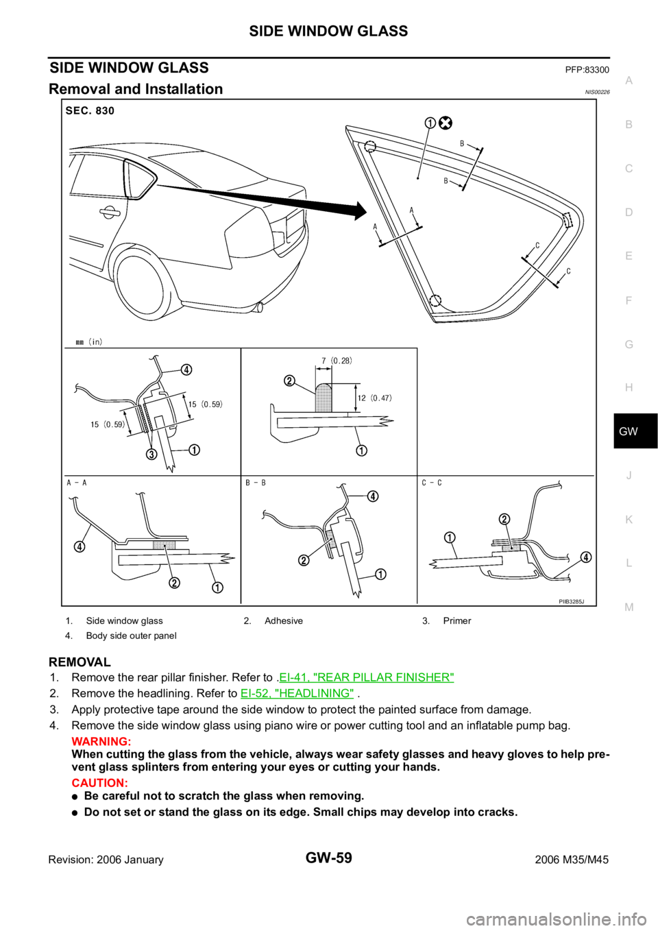
Removal and InstallationNIS00226
REMOVAL
1. Remove the rear pillar finisher. Refer to .EI-41, "REAR PILLAR FINISHER"
2. Remove the headlining. Refer to EI-52, "HEADLINING" .
3. Apply protective tape around the side window to protect the painted surface from damage.
4. Remove the side window glass using piano wire or power cutting tool and an inflatable pump bag.
WAR NING :
When cutting the glass from the vehicle, always wear safety glasses and heavy gloves to help pre-
vent glass splinters from entering your eyes or cutting your hands.
CAUTION:
Be careful not to scratch the glass when removing.
Do not set or stand the glass on its edge. Small chips may develop into cracks.
PIIB3285J
1. Side window glass 2. Adhesive 3. Primer
4. Body side outer panel
Page 3580 of 5621
REAR WINDOW GLASS AND MOLDING
GW-61
C
D
E
F
G
H
J
K
L
MA
B
GW
Revision: 2006 January2006 M35/M45
REAR WINDOW GLASS AND MOLDINGPFP:79712
Removal and InstallationNIS00227
REMOVAL
1. Remove rear seatback and rear seat cushion. Refer to SE-172, "REAR SEAT" .
2. Remove the rear pillar finisher. Refer to EI-41, "
REAR PILLAR FINISHER" .
3. Remove the rear parcel shelf finisher. Refer to EI-42, "
REAR PARCEL SHELF FINISHER" .
4. Remove the rear of the headlining. Refer to EI-52, "
HEADLINING" .
5. Remove the connectors and grounds for the rear window defogger and printed antenna.
6. Remove the roof side molding. Refer to EI-25, "
ROOF SIDE MOLDING" .
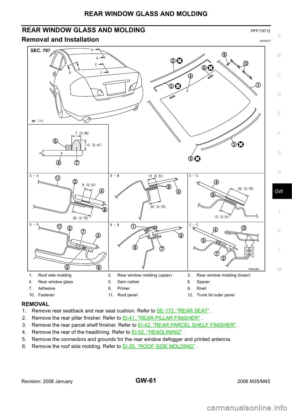
1. Roof side molding 2. Rear window molding (upper) 3. Rear window molding (lower)
4. Rear window glass 5. Dam rubber 6. Spacer
7. Adhesive 8. Primer 9. Rivet
10. Fastener 11. Roof panel 12. Trunk lid outer panel
PIIB3286J
Page 3587 of 5621
GW-68
REAR DOOR GLASS AND REGULATOR
Revision: 2006 January2006 M35/M45
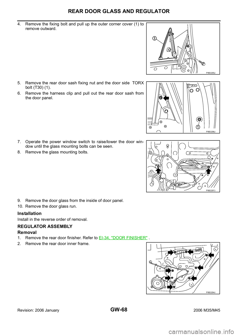
4. Remove the fixing bolt and pull up the outer corner cover (1) to
remove outward.
5. Remove the rear door sash fixing nut and the door side TORX
bolt (T30) (1).
6. Remove the harness clip and pull out the rear door sash from
the door panel.
7. Operate the power window switch to raise/lower the door win-
dow until the glass mounting bolts can be seen.
8. Remove the glass mounting bolts.
9. Remove the door glass from the inside of door panel.
10. Remove the door glass run.
Installation
Install in the reverse order of removal.
REGULATOR ASSEMBLY
Removal
1. Remove the rear door finisher. Refer to EI-34, "DOOR FINISHER" .
2. Remove the rear door inner frame.
PIIB3295J
PIIB3296J
PIIB3297J
PIIB3294J
Page 3588 of 5621
REAR DOOR GLASS AND REGULATOR
GW-69
C
D
E
F
G
H
J
K
L
MA
B
GW
Revision: 2006 January2006 M35/M45
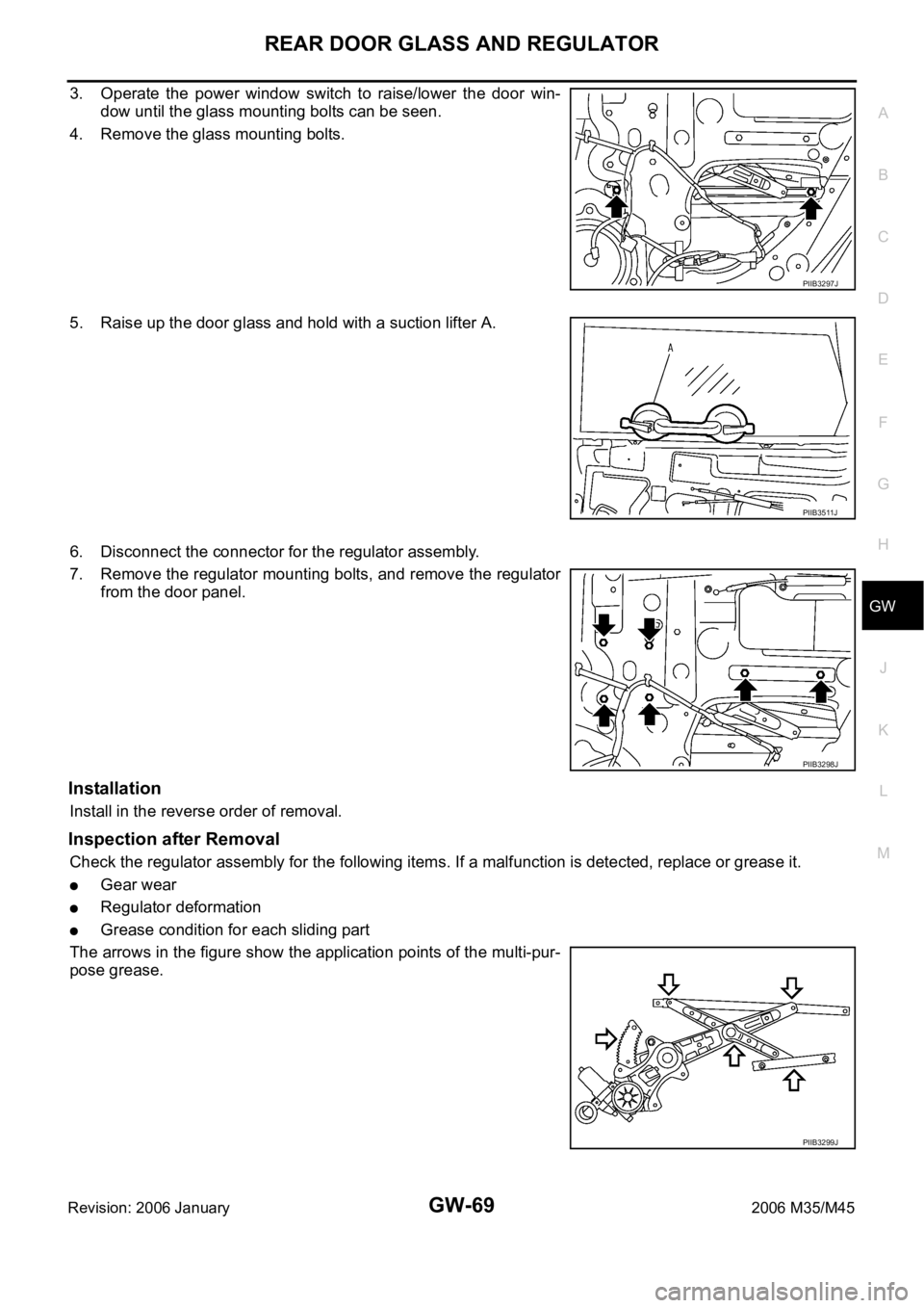
3. Operate the power window switch to raise/lower the door win-
dow until the glass mounting bolts can be seen.
4. Remove the glass mounting bolts.
5. Raise up the door glass and hold with a suction lifter A.
6. Disconnect the connector for the regulator assembly.
7. Remove the regulator mounting bolts, and remove the regulator
from the door panel.
Installation
Install in the reverse order of removal.
Inspection after Removal
Check the regulator assembly for the following items. If a malfunction is detected, replace or grease it.
Gear wear
Regulator deformation
Grease condition for each sliding part
The arrows in the figure show the application points of the multi-pur-
pose grease.
PIIB3297J
PIIB3511J
PIIB3298J
PIIB3299J