Page 4618 of 5621
ACTIVE AFS
LT-191
C
D
E
F
G
H
I
J
L
MA
B
LT
Revision: 2006 January2006 M35/M45
Removal and Installation of AFS Control UnitNKS003QZ
REMOVAL
1. Remove dash side finisher RH. Refer to EI-37, "BODY SIDE TRIM" in EI section.
2. Remove screw (A).
3. Disconnect AFS control unit connector.
4. Remove AFS control unit (1).
INSTALLATION
Installation is the reverse order of removal.
Removal and Installation of AFS SwitchNKS003R0
REMOVAL
1. Remove instrument lower driver panel. Refer to IP-10, "INSTRUMENT PANEL ASSEMBLY" in IP section.
2. Press AFS switch fixing pawls (A) and remove unit (1) from
instrument lower driver panel.
INSTALLATION
Installation is the reverse order of removal.
SKIB4766E
SKIB4768E
Page 4657 of 5621
LT-230
LIGHTING AND TURN SIGNAL SWITCH
Revision: 2006 January2006 M35/M45
LIGHTING AND TURN SIGNAL SWITCHPFP:25540
Removal and InstallationNKS003S2
REMOVAL
1. Remove steering column lower cover. Refer to IP-10, "INSTRUMENT PANEL ASSEMBLY" .
2. While pressing pawls (A) in direction as shown in the figure, pull
lighting and turn signal switch (1) toward driver door and discon-
nect from the base.
INSTALLATION
Installation is the reverse order of removal.
Switch Circuit InspectionNKS003S3
Refer to LT- 2 4 0 , "Combination Switch Inspection" .
SKIB4186E
Page 4740 of 5621
ILLUMINATION
LT-313
C
D
E
F
G
H
I
J
L
MA
B
LT
Revision: 2006 January2006 M35/M45
Glove Box LampNKS003TM
BULB REPLACEMENT, REMOVAL AND INSTALLATION
Removal
1. Remove glove box cover. Refer to IP-10, "INSTRUMENT PANEL ASSEMBLY" .
2. Turn globe box lamp bulb socket (1) counterclockwise and
unlock it.
3. Remove bulb (2).
Installation
Installation is the reverse order of removal.
Cigarette Lighter IlluminationNKS003TN
BULB REPLACEMENT, REMOVAL AND INSTALLATION
Removal
1. Remove A/T console finisher. Refer to IP-11, "Removal and Installation of Instrument Panel & Pad" .
2. Remove screws (A).
3. Use a screwdriver to undo hooks, remove bulb sockets (1).
4. Remove bulb (2).
Installation
Installation is the reverse order of removal.Glove box lamp : 12V - 1.4W
SKIB4206E
SKIB4207E
Front ashtray and cigarette lighter
illumination: 12V - 1.4W
SKIB4209E
Page 4823 of 5621

PB-4
PARKING BRAKE CONTROL
Revision: 2006 January2006 M35/M45
Removal and InstallationNFS000PT
REMOVAL
1. Remove rear tires from vehicle with power tool.
2. Remove instrument driver lower panel. Refer to IP-10, "
INSTRUMENT PANEL ASSEMBLY" .
3. Disconnect parking brake switch connector.
4. Remove adjusting nut and loosen front cable.
5. Remove device assembly mounting nuts and remove device assembly from vehicle.
6. Remove center console. Refer to IP-19, "
CENTER CONSOLE ASSEMBLY" .
7. Separate rear cable from front cable, remove front cable from vehicle.
8. Remove heat insulator of the exhaust center tube from vehicle.
9. Remove parking brake shoe, and remove rear cable from toggle lever. Refer to PB-6, "
Removal and
Installation" .
10. Remove rear cable mounting bolts and nuts, pull out rear cable from vehicle.
INSTALLATION
1. Install in the reverse order of the removal. Refer to PB-3, "Components" for tightening torque.
CAUTION:
Do not reuse adjusting nut.
2. Adjust parking brake. Refer to PB-2, "
ADJUSTMENT" .
Page 4892 of 5621
HARNESS
PG-65
C
D
E
F
G
H
I
J
L
MA
B
PG
Revision: 2006 January2006 M35/M45
MAIN HARNESS
Instrument Panel
TKIT0442E
Page 4967 of 5621

PS-14
STEERING COLUMN
Revision: 2006 January2006 M35/M45
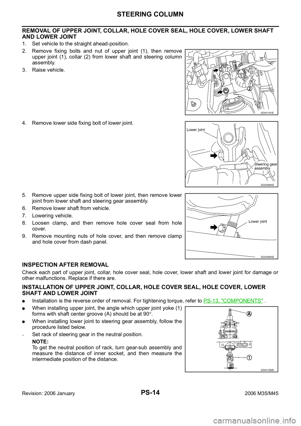
REMOVAL OF UPPER JOINT, COLLAR, HOLE COVER SEAL, HOLE COVER, LOWER SHAFT
AND LOWER JOINT
1. Set vehicle to the straight ahead-position.
2. Remove fixing bolts and nut of upper joint (1), then remove
upper joint (1), collar (2) from lower shaft and steering column
assembly.
3. Raise vehicle.
4. Remove lower side fixing bolt of lower joint.
5. Remove upper side fixing bolt of lower joint, then remove lower
joint from lower shaft and steering gear assembly.
6. Remove lower shaft from vehicle.
7. Lowering vehicle.
8. Loosen clamp, and then remove hole cover seal from hole
cover.
9. Remove mounting nuts of hole cover, and then remove clamp
and hole cover from dash panel.
INSPECTION AFTER REMOVAL
Check each part of upper joint, collar, hole cover seal, hole cover, lower shaft and lower joint for damage or
other malfunctions. Replace if there are.
INSTALLATION OF UPPER JOINT, COLLAR, HOLE COVER SEAL, HOLE COVER, LOWER
SHAFT AND LOWER JOINT
Installation is the reverse order of removal. For tightening torque, refer to PS-13, "COMPONENTS" .
When installing upper joint, the angle which upper joint yoke (1)
forms with shaft center groove (A) should be at 90
.
When installing lower joint to steering gear assembly, follow the
procedure listed below.
–Set rack of steering gear in the neutral position.
NOTE:
To get the neutral position of rack, turn gear-sub assembly and
measure the distance of inner socket, and then measure the
intermediate position of the distance.
SGIA1181E
SGIA0844E
SGIA0845E
SGIA1290E
Page 4968 of 5621

STEERING COLUMN
PS-15
C
D
E
F
H
I
J
K
L
MA
B
PS
Revision: 2006 January2006 M35/M45
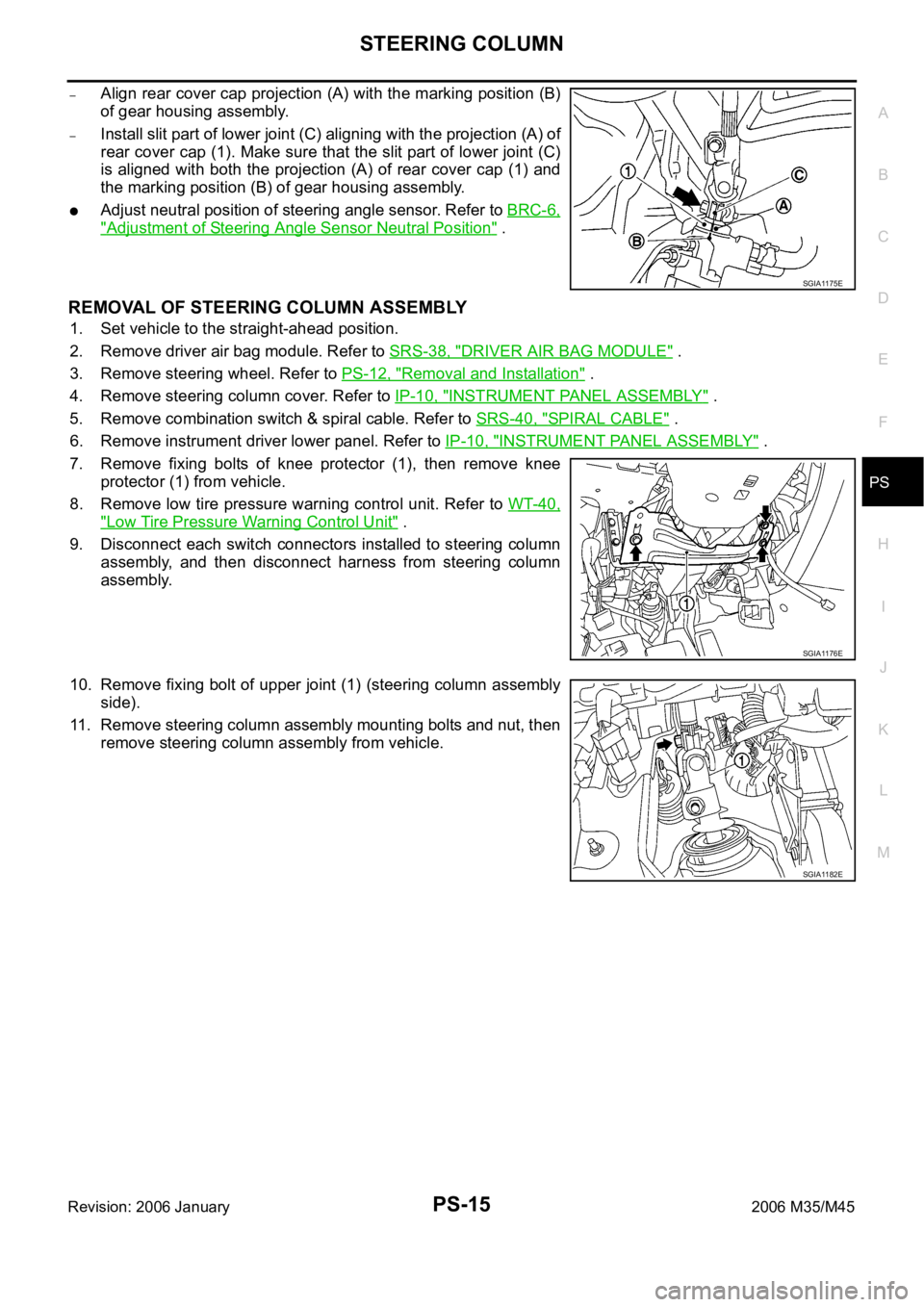
–Align rear cover cap projection (A) with the marking position (B)
of gear housing assembly.
–Install slit part of lower joint (C) aligning with the projection (A) of
rear cover cap (1). Make sure that the slit part of lower joint (C)
is aligned with both the projection (A) of rear cover cap (1) and
the marking position (B) of gear housing assembly.
Adjust neutral position of steering angle sensor. Refer to BRC-6,
"Adjustment of Steering Angle Sensor Neutral Position" .
REMOVAL OF STEERING COLUMN ASSEMBLY
1. Set vehicle to the straight-ahead position.
2. Remove driver air bag module. Refer to SRS-38, "
DRIVER AIR BAG MODULE" .
3. Remove steering wheel. Refer to PS-12, "
Removal and Installation" .
4. Remove steering column cover. Refer to IP-10, "
INSTRUMENT PANEL ASSEMBLY" .
5. Remove combination switch & spiral cable. Refer to SRS-40, "
SPIRAL CABLE" .
6. Remove instrument driver lower panel. Refer to IP-10, "
INSTRUMENT PANEL ASSEMBLY" .
7. Remove fixing bolts of knee protector (1), then remove knee
protector (1) from vehicle.
8. Remove low tire pressure warning control unit. Refer to WT-40,
"Low Tire Pressure Warning Control Unit" .
9. Disconnect each switch connectors installed to steering column
assembly, and then disconnect harness from steering column
assembly.
10. Remove fixing bolt of upper joint (1) (steering column assembly
side).
11. Remove steering column assembly mounting bolts and nut, then
remove steering column assembly from vehicle.
SGIA1175E
SGIA1176E
SGIA1182E
Page 5014 of 5621

RF-1
ROOF
I BODY
CONTENTS
C
D
E
F
G
H
J
K
L
M
SECTION RF
A
B
RF
Revision: 2006 January2006 M35/M45
ROOF
PRECAUTIONS .......................................................... 2
Precautions for Supplemental Restraint System
(SRS) “AIR BAG” and “SEAT BELT PRE-TEN-
SIONER” .................................................................. 2
Precautions .............................................................. 2
PREPARATION ........................................................... 3
Special Service Tools ............................................... 3
Commercial Service Tools ........................................ 3
SQUEAK AND RATTLE TROUBLE DIAGNOSES ..... 4
Work Flow ................................................................ 4
CUSTOMER INTERVIEW ..................................... 4
DUPLICATE THE NOISE AND TEST DRIVE ....... 5
CHECK RELATED SERVICE BULLETINS ........... 5
LOCATE THE NOISE AND IDENTIFY THE
ROOT CAUSE ...................................................... 5
REPAIR THE CAUSE ........................................... 5
CONFIRM THE REPAIR ....................................... 6
Generic Squeak and Rattle Troubleshooting ........... 6
INSTRUMENT PANEL .......................................... 6
CENTER CONSOLE ............................................. 6
DOORS ................................................................. 6
TRUNK .................................................................. 7
SUNROOF/HEADLINING ..................................... 7
SEATS ................................................................... 7
UNDERHOOD ....................................................... 7
Diagnostic Worksheet .............................................. 8
SUNROOF ................................................................ 10
Component Parts and Harness Connector Location ... 10
System Description ................................................. 11
TILT UP / SLIDE CLOSE OPERATION ................ 11TILT DOWN / SLIDE OPEN OPERATION .......... 11
AUTO OPERATION ............................................. 11
RETAINED POWER OPERATION ...................... 11
ANTI-PINCH FUNCTION .................................... 12
INITIALIZATION PROCEDURE .......................... 12
Wiring Diagram — SROOF — ................................ 13
Terminals and Reference Value for BCM ............... 15
Terminals and Reference Value for Sunroof Motor
Assembly ................................................................ 15
CONSULT-II Function (BCM) ................................. 16
ACTIVE TEST ..................................................... 17
WORK SUPPORT ............................................... 17
DATE MONITOR ................................................. 17
Work Flow ............................................................... 18
Diagnosis Symptom Chart ...................................... 18
BCM Power Supply and Ground Circuit Check ...... 18
Sunroof Motor Assembly Power Supply and Ground
Circuit Check .......................................................... 19
Sunroof Switch Check .........................................
... 21
Door Switch Check ..............................................
... 23
Fitting Adjustment ................................................... 25
RID WEATHERSTRIP OVERLAP ADJUST-
MENT AND SURFACE MISMATCH ADJUST-
MENT .................................................................. 25
Removal and Installation ........................................ 25
SUNROOF UNIT ................................................. 27
Disassembly and Assembly .................................... 28
DISASSEMBLY ................................................... 29
ASSEMBLY ......................................................... 29