2006 INFINITI M35 ground
[x] Cancel search: groundPage 3633 of 5621
GW-114
REVERSE INTERLOCK DOOR MIRROR SYSTEM
Revision: 2006 January2006 M35/M45
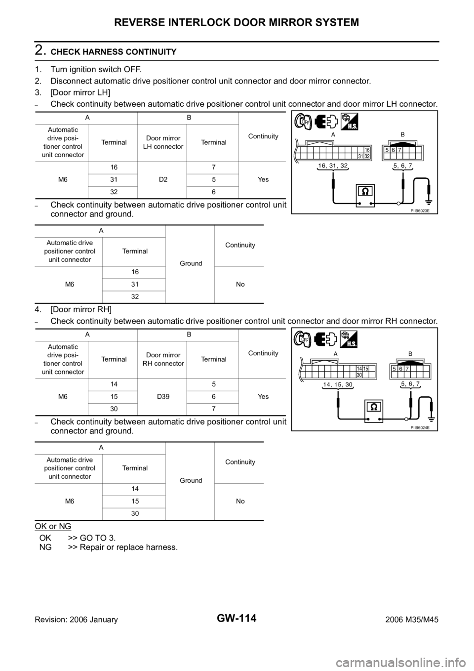
2. CHECK HARNESS CONTINUITY
1. Turn ignition switch OFF.
2. Disconnect automatic drive positioner control unit connector and door mirror connector.
3. [Door mirror LH]
–Check continuity between automatic drive positioner control unit connector and door mirror LH connector.
–Check continuity between automatic drive positioner control unit
connector and ground.
4. [Door mirror RH]
–Check continuity between automatic drive positioner control unit connector and door mirror RH connector.
–Check continuity between automatic drive positioner control unit
connector and ground.
OK or NG
OK >> GO TO 3.
NG >> Repair or replace harness.
AB
Continuity Automatic
drive posi-
tioner control
unit connectorTerminalDoor mirror
LH connectorTerminal
M616
D27
Ye s 31 5
32 6
A
GroundContinuity Automatic drive
positioner control
unit connectorTerminal
M616
No 31
32
AB
Continuity Automatic
drive posi-
tioner control
unit connectorTerminalDoor mirror
RH connectorTerminal
M614
D395
Ye s 15 6
30 7
A
GroundContinuity Automatic drive
positioner control
unit connectorTerminal
M614
No 15
30
PIIB6023E
PIIB6024E
Page 3634 of 5621
REVERSE INTERLOCK DOOR MIRROR SYSTEM
GW-115
C
D
E
F
G
H
J
K
L
MA
B
GW
Revision: 2006 January2006 M35/M45
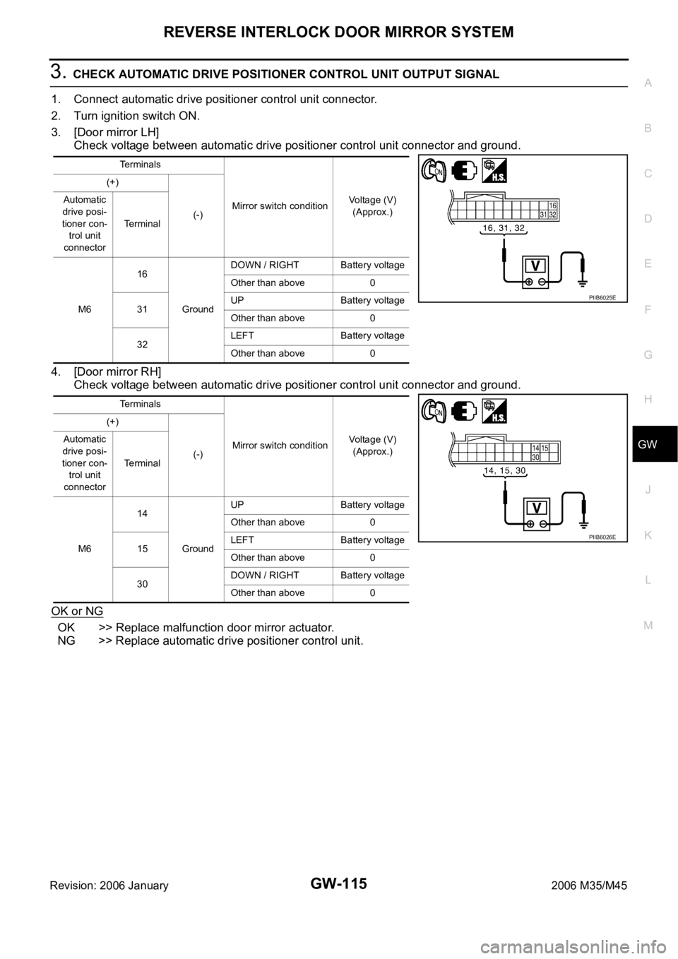
3. CHECK AUTOMATIC DRIVE POSITIONER CONTROL UNIT OUTPUT SIGNAL
1. Connect automatic drive positioner control unit connector.
2. Turn ignition switch ON.
3. [Door mirror LH]
Check voltage between automatic drive positioner control unit connector and ground.
4. [Door mirror RH]
Check voltage between automatic drive positioner control unit connector and ground.
OK or NG
OK >> Replace malfunction door mirror actuator.
NG >> Replace automatic drive positioner control unit.
Terminals
Mirror switch conditionVoltage (V)
(Approx.) (+)
(-) Automatic
drive posi-
tioner con-
trol unit
connectorTerminal
M616
GroundDOWN / RIGHT Battery voltage
Other than above 0
31UP Battery voltage
Other than above 0
32LEFT Battery voltage
Other than above 0
Terminals
Mirror switch conditionVoltage (V)
(Approx.) (+)
(-) Automatic
drive posi-
tioner con-
trol unit
connectorTerminal
M614
GroundUP Battery voltage
Other than above 0
15LEFT Battery voltage
Other than above 0
30DOWN / RIGHT Battery voltage
Other than above 0
PIIB6025E
PIIB6026E
Page 3635 of 5621
GW-116
REVERSE INTERLOCK DOOR MIRROR SYSTEM
Revision: 2006 January2006 M35/M45
Check Mirror Sensor Circuit Check NIS0023E
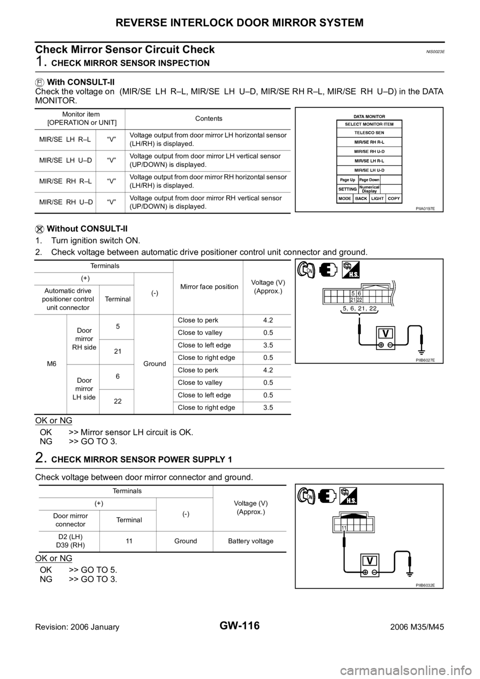
1. CHECK MIRROR SENSOR INSPECTION
With CONSULT-II
Check the voltage on (MIR/SE LH R–L, MIR/SE LH U–D, MIR/SE RH R–L, MIR/SE RH U–D) in the DATA
MONITOR.
Without CONSULT-II
1. Turn ignition switch ON.
2. Check voltage between automatic drive positioner control unit connector and ground.
OK or NG
OK >> Mirror sensor LH circuit is OK.
NG >> GO TO 3.
2. CHECK MIRROR SENSOR POWER SUPPLY 1
Check voltage between door mirror connector and ground.
OK or NG
OK >> GO TO 5.
NG >> GO TO 3.
Monitor item
[OPERATION or UNIT]Contents
MIR/SE LH R–L “V”Voltage output from door mirror LH horizontal sensor
(LH/RH) is displayed.
MIR/SE LH U–D “V”Voltage output from door mirror LH vertical sensor
(UP/DOWN) is displayed.
MIR/SE RH R–L “V”Voltage output from door mirror RH horizontal sensor
(LH/RH) is displayed.
MIR/SE RH U–D “V”Voltage output from door mirror RH vertical sensor
(UP/DOWN) is displayed.
PIIA0197E
Terminals
Mirror face positionVoltage (V)
(Approx.) (+)
(-) Automatic drive
positioner control
unit connectorTerminal
M6Door
mirror
RH side5
GroundClose to perk 4.2
Close to valley 0.5
21Close to left edge 3.5
Close to right edge 0.5
Door
mirror
LH side6Close to perk 4.2
Close to valley 0.5
22Close to left edge 0.5
Close to right edge 3.5
PIIB6027E
Terminals
Voltage (V)
(Approx.) (+)
(-)
Door mirror
connectorTe r m i n a l
D2 (LH)
D39 (RH)11 Ground Battery voltage
PIIB6032E
Page 3636 of 5621
REVERSE INTERLOCK DOOR MIRROR SYSTEM
GW-117
C
D
E
F
G
H
J
K
L
MA
B
GW
Revision: 2006 January2006 M35/M45
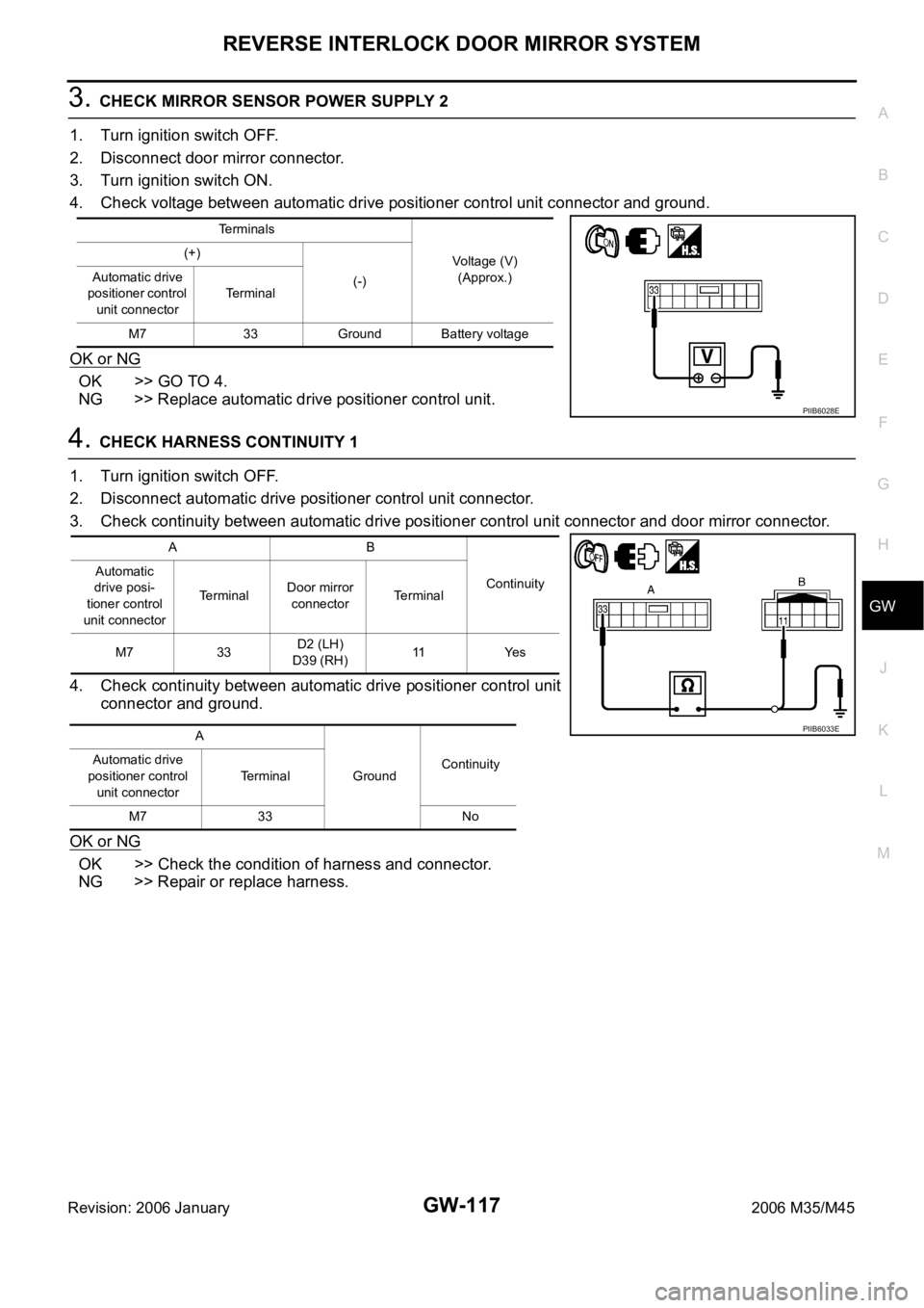
3. CHECK MIRROR SENSOR POWER SUPPLY 2
1. Turn ignition switch OFF.
2. Disconnect door mirror connector.
3. Turn ignition switch ON.
4. Check voltage between automatic drive positioner control unit connector and ground.
OK or NG
OK >> GO TO 4.
NG >> Replace automatic drive positioner control unit.
4. CHECK HARNESS CONTINUITY 1
1. Turn ignition switch OFF.
2. Disconnect automatic drive positioner control unit connector.
3. Check continuity between automatic drive positioner control unit connector and door mirror connector.
4. Check continuity between automatic drive positioner control unit
connector and ground.
OK or NG
OK >> Check the condition of harness and connector.
NG >> Repair or replace harness.
Terminals
Voltage (V)
(Approx.) (+)
(-) Automatic drive
positioner control
unit connectorTerminal
M7 33 Ground Battery voltage
PIIB6028E
AB
Continuity Automatic
drive posi-
tioner control
unit connectorTerminalDoor mirror
connectorTerminal
M7 33D2 (LH)
D39 (RH)11 Ye s
A
GroundContinuity Automatic drive
positioner control
unit connectorTerminal
M7 33 No
PIIB6033E
Page 3637 of 5621
GW-118
REVERSE INTERLOCK DOOR MIRROR SYSTEM
Revision: 2006 January2006 M35/M45
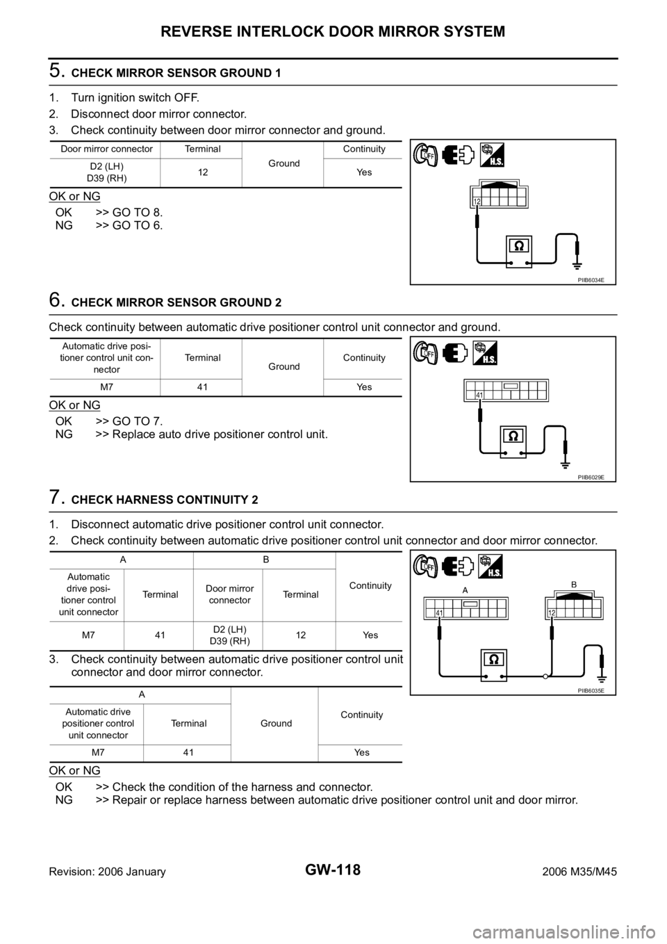
5. CHECK MIRROR SENSOR GROUND 1
1. Turn ignition switch OFF.
2. Disconnect door mirror connector.
3. Check continuity between door mirror connector and ground.
OK or NG
OK >> GO TO 8.
NG >> GO TO 6.
6. CHECK MIRROR SENSOR GROUND 2
Check continuity between automatic drive positioner control unit connector and ground.
OK or NG
OK >> GO TO 7.
NG >> Replace auto drive positioner control unit.
7. CHECK HARNESS CONTINUITY 2
1. Disconnect automatic drive positioner control unit connector.
2. Check continuity between automatic drive positioner control unit connector and door mirror connector.
3. Check continuity between automatic drive positioner control unit
connector and door mirror connector.
OK or NG
OK >> Check the condition of the harness and connector.
NG >> Repair or replace harness between automatic drive positioner control unit and door mirror.
Door mirror connector Terminal
GroundContinuity
D2 (LH)
D39 (RH)12 Yes
PIIB6034E
Automatic drive posi-
tioner control unit con-
nectorTerminal
GroundContinuity
M7 41 Yes
PIIB6029E
AB
Continuity Automatic
drive posi-
tioner control
unit connectorTerminalDoor mirror
connectorTerminal
M7 41D2 (LH)
D39 (RH)12 Yes
A
GroundContinuity Automatic drive
positioner control
unit connectorTerminal
M7 41 Yes
PIIB6035E
Page 3638 of 5621
REVERSE INTERLOCK DOOR MIRROR SYSTEM
GW-119
C
D
E
F
G
H
J
K
L
MA
B
GW
Revision: 2006 January2006 M35/M45
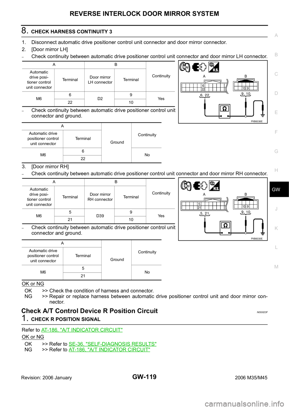
8. CHECK HARNESS CONTINUITY 3
1. Disconnect automatic drive positioner control unit connector and door mirror connector.
2. [Door mirror LH]
–Check continuity between automatic drive positioner control unit connector and door mirror LH connector.
–Check continuity between automatic drive positioner control unit
connector and ground.
3. [Door mirror RH]
–Check continuity between automatic drive positioner control unit connector and door mirror RH connector.
–Check continuity between automatic drive positioner control unit
connector and ground.
OK or NG
OK >> Check the condition of harness and connector.
NG >> Repair or replace harness between automatic drive positioner control unit and door mirror con-
nector.
Check A/T Control Device R Position CircuitNIS0023F
1. CHECK R POSITION SIGNAL
Refer to AT-186, "
A/T INDICATOR CIRCUIT"
OK or NG
OK >> Refer to SE-36, "SELF-DIAGNOSIS RESULTS"
NG >> Refer to AT-186, "A/T INDICATOR CIRCUIT"
AB
Continuity Automatic
drive posi-
tioner control
unit connectorTerminalDoor mirror
LH connectorTerminal
M66
D29
Ye s
22 10
A
GroundContinuity Automatic drive
positioner control
unit connectorTerminal
M66
No
22
AB
Continuity Automatic
drive posi-
tioner control
unit connectorTerminalDoor mirror
RH connectorTerminal
M65
D399
Ye s
21 10
A
GroundContinuity Automatic drive
positioner control
unit connectorTerminal
M65
No
21
PIIB6036E
PIIB6030E
Page 3645 of 5621
IDX-4
ALPHABETICAL INDEX
Electronic ignition (EI) system ............. EC-33, EC-743
Engine control module (ECM) .......... EC-496, EC-1215
Engine control system diagram ........... EC-30, EC-740
Engine coolant temperature sensor (ECTS) ... EC-226,
EC-238
, EC-948, EC-961
Engine coolant(VK45DE) .................................. CO-40
Engine coolant(VQ35DE) ................................. CO-11
Engine oil filter replacement ............................. MA-26
Engine oil filter replacement(VQ35DE) ............. MA-19
Engine oil precautions .......................................... GI-8
Engine oil replacement(VQ35DE) ..................... MA-18
Engine oil(VK45DE) ........................................... LU-26
Engine oil(VQ35DE) ............................................ LU-7
Engine removal(VK45DE) ............................... EM-244
Engine removal(VQ35DE) .............................. EM-113
Engine room cover ............................................ EM-14
Engine room cover(VK45DE) ......................... EM-173
ETC1 - Wiring diagram .................... EC-614, EC-1345
ETC2 - Wiring diagram .................... EC-609, EC-1340
ETC3 - Wiring diagram .................... EC-620, EC-1352
EVAP canister ...................................... EC-42, EC-752
EVAP canister purge volume control solenoid valve ....
EC-412
, EC-420, EC-1132, EC-1140
EVAP canister vent control valve ...... EC-427, EC-434,
EC-1147
, EC-1154
EVAP control system (small leak) diagnosis .. EC-403,
EC-466
, EC-1124, EC-1185
EVAP control system pressure sensor ........... EC-440,
EC-443
, EC-450, EC-1160, EC-1163, EC-1170
EVAP control system purge flow monitoring diagnosis
EC-398
, EC-1119
EVAP vapor lines inspection ................. MA-21, MA-28
Evaporative emission (EVAP) system . EC-39, EC-749
Evaporator ..................................................... ATC-168
Exhaust manifold(VK45DE) ............................ EM-183
Exhaust system ................................................... EX-3
Exhaust system inspection ..................... EX-3, MA-29
Expansion valve ............................................. ATC-169
F
F/FOG - Wiring diagram ................................... LT-197
F/PUMP - Wiring diagram ................ EC-686, EC-1428
Final drive pre-inspection .................. FFD-16, RFD-19
Final drive removal and installation .. FFD-13, RFD-16
Floor trim ............................................................. EI-50
Flow charts ......................................................... GI-28
Fluid temperature sensor (A/T) ........................ AT-135
Fluorescent leak detector .............................. ATC-170
FPCM - Wiring diagram ................... EC-527, EC-1253
Freeze frame data ............................... EC-59, EC-770
Front brake solenoid valve ................. AT-151, AT-153
Front bumper ...................................................... EI-11
Front combination lamp removal and installation LT-76
Front door ............................. BL-190, BL-196, GW-63
Front passenger air bag .................................. SRS-42
Front seat belt .................................................... SB-30
Front seat belt pre-tensioner ..... SB-2, SRS-3, SRS-47
Front washer ...................................................... WW-4
Front wiper ......................................................... WW-4
FTS - Wiring diagram ....................................... AT-136
FTTS - Wiring diagram .... EC-345, EC-350, EC-1068,
EC-1073
Fuel cut control (at no load high engine speed) EC-34,
EC-744
Fuel filter replacement ......................................... FL-4
Fuel gauge ............................................................ DI-5
Fuel injection system (Bank 1) ......... EC-321, EC-332,
EC-1044
, EC-1055
Fuel injection system (Bank 2) ......... EC-321, EC-332,
EC-1044
, EC-1055
Fuel injector ................................................... EC-1420
Fuel injector and fuel tube(VK45DE) .............. EM-193
Fuel injector and fuel tube(VQ35DE) ................ EM-45
Fuel level sensor EC-475, EC-477, EC-479, EC-1194,
EC-1196
, EC-1198
Fuel line inspection .................................. FL-3, MA-25
Fuel line inspection(VQ35DE) .......................... MA-18
Fuel precautions ................................................... GI-6
Fuel pressure check ........................... EC-98, EC-809
Fuel pressure release ......................... EC-98, EC-809
Fuel pump ....................................... EC-685, EC-1427
Fuel pump and gauge .......................................... FL-4
Fuel pump control module .............. EC-525, EC-1251
Fuel pump dropping resistor ........... EC-525, EC-1251
Fuel system ......................................................... FL-3
Fuel tank ............................................................ FL-10
Fuel tank temperature sensor .......... EC-343, EC-349,
EC-1066
, EC-1072
Fuel tank vacuum relief valve ............. EC-42, EC-752
FUELB1 - Wiring diagram EC-323, EC-334, EC-1046,
EC-1057
FUELB2 - Wiring diagram EC-325, EC-336, EC-1048,
EC-1059
Fuse .................................................................. PG-17
Fuse and fusible link box ................................ PG-112
Fusible link ........................................................ PG-17
G
Gauges ................................................................. DI-5
Generator ........................................................... SC-23
Generator - See Alternator ................................ SC-23
Glass ........................ GW-11, GW-61, GW-63, GW-67
Grille - See Exterior ............................................ EI-16
Ground distribution ........................................... PG-46
H
H/LAMP - Wiring diagram ....................... LT-13
, LT-48
Harness connector .......................................... PG-102
Harness layout .................................................. PG-63
Hazard warning lamp ....................................... LT-211
Headlamp removal and installation .................... LT-76
Headlining - See Roof trim .................................. EI-52
Heated oxygen sensor 2 (bank 1) .... EC-286, EC-297,
EC-310
, EC-1009, EC-1020, EC-1033
Heated oxygen sensor 2 (bank 2) .... EC-286, EC-297,
Page 3678 of 5621
![INFINITI M35 2006 Factory Service Manual TROUBLE DIAGNOSES WORK FLOW
LAN-9
[CAN]
C
D
E
F
G
H
I
J
L
MA
B
LAN
Revision: 2006 January2006 M35/M45
TROUBLE DIAGNOSES WORK FLOWPFP:00004
When Displaying CAN Communication System ErrorsNKS003XS
WHEN INFINITI M35 2006 Factory Service Manual TROUBLE DIAGNOSES WORK FLOW
LAN-9
[CAN]
C
D
E
F
G
H
I
J
L
MA
B
LAN
Revision: 2006 January2006 M35/M45
TROUBLE DIAGNOSES WORK FLOWPFP:00004
When Displaying CAN Communication System ErrorsNKS003XS
WHEN](/manual-img/42/57023/w960_57023-3677.png)
TROUBLE DIAGNOSES WORK FLOW
LAN-9
[CAN]
C
D
E
F
G
H
I
J
L
MA
B
LAN
Revision: 2006 January2006 M35/M45
TROUBLE DIAGNOSES WORK FLOWPFP:00004
When Displaying CAN Communication System ErrorsNKS003XS
WHEN A MALFUNCTION IS DETECTED BY CAN COMMUNICATION SYSTEM
CAN communication line is open. (CAN H, CAN L, or both)
CAN communication line is shorted. (Ground, between CAN lines, or other harnesses)
The areas related to CAN communication of unit is malfunctioning.
WHEN A MALFUNCTION IS DETECTED EXCEPT CAN COMMUNICATION SYSTEM
Removal and installation of parts: When the units that perform CAN communication or the sensors related
to CAN communication are removed and installed, malfunction may be detected (or DTC other than CAN
communication may be detected).
Fuse blown out (removed): CAN communication of the unit may be stopped at such time.
Low voltage: If the voltage decreases because of battery discharge when IGN is ON, malfunction may be
detected by self-diagnosis according to the units.