2006 INFINITI M35 radiator
[x] Cancel search: radiatorPage 3647 of 5621
IDX-6
ALPHABETICAL INDEX
Meter ..................................................................... DI-5
METER - Wiring diagram .................................... DI-13
MIL data link connectors circuit ....... EC-722, EC-1459
MIL/DL - Wiring diagram .................. EC-722, EC-1459
MIRROR - Wiring diagram ................................ GW-99
Mirror, door ..................................................... GW-120
Mirror, out side ................................................ GW-120
Misfire .............................................. EC-361, EC-1084
MMSW - Wiring diagram .................................. AT-168
Mode door control linkage adjustment ATC-79, ATC-82
Mode door motor .............. ATC-75, ATC-80, ATC-140
Molding - See Exterior .............................. EI-25, EI-29
Mud guard - See Exterior .................................... EI-22
Multiport fuel injection (MFI) system .... EC-31, EC-741
Multiport fuel injection precautions ....................... GI-7
N
NATS - Wiring diagram .................................... BL-256
NONDTC - Wiring diagram .............................. AT-187
NVH troubleshooting (EM) .............................. EM-171
NVH troubleshooting (EM)(VQ35DE) ............... EM-12
NVH troubleshooting (Final drive) ......... FFD-6, RFD-7
NVH troubleshooting (Propeller shaft) ................. PR-3
NVH troubleshooting (Transfer) ........................... TF-8
NVIS (Nissan vehicle immobilizer system) precautions
GI-3
O
O2H2B1 - Wiring diagram .................. EC-191
, EC-913
O2H2B2 - Wiring diagram .................. EC-193, EC-915
O2S2B1 - Wiring diagram .. EC-289, EC-300, EC-313,
EC-1012
, EC-1023, EC-1036
O2S2B2 - Wiring diagram .. EC-291, EC-302, EC-315,
EC-1014
, EC-1025, EC-1038
Oil cooler (engine)(VQ35DE) ............................. LU-14
Oil filter(VK45DE) .............................................. LU-29
Oil filter(VQ35DE) .............................................. LU-10
Oil pan (engine)(VK45DE) .............................. EM-187
Oil pan (engine)(VQ35DE) ................................ EM-29
Oil pressure (engine)(VK45DE) ......................... LU-26
Oil pressure (engine)(VQ35DE) ........................... LU-8
Oil pressure relief valve (engine)(VQ35DE) ........ LU-6
Oil pump (A/T) ................................................. AT-318
Oil pump (engine)(VK45DE) .............................. LU-30
Oil pump (engine)(VQ35DE) .............................. LU-18
Oil pump regulator valve (engine)(VK45DE) ..... LU-30
Oil pump regulator valve (engine)(VQ35DE) ..... LU-18
Oil seal replacement (engine)(VK45DE) ......... EM-229
Oil seal replacement (engine)(VQ35DE) .......... EM-98
Oil seal replacement (front of final drive) .......... FFD-9,
RFD-10
Oil seal replacement (side of final drive) ......... FFD-11,
RFD-14
On board diagnostic system ................ EC-54, EC-764
ORVR (On-board Refueling Vapor Recovery) .. EC-46,
EC-756
Out side mirror ................................................ GW-120
Overheat ......................................... EC-512, EC-1239
P
P/SCKT - Wiring diagram ................................ WW-51
Park/Neutral position switch ........... EC-504, EC-1223
Park/neutral position switch (A/T) .................... AT-113
Parking brake control ........................................... PB-3
Parking lamp .................................................... LT-249
PCV (positive crankcase ventilation) .. EC-51, EC-761
PGC/V - Wiring diagram .. EC-414, EC-422, EC-1134,
EC-1142
PHASE - Wiring diagram ............................... EC-1108
PHSB1 - Wiring diagram .................................. EC-385
PHSB2 - Wiring diagram .................................. EC-387
Pilot bushing replacement - See Pilot
converter(VQ35DE) ........................................ EM-124
Piston assembly(VK45DE) ............................. EM-260
Piston assembly(VQ35DE) ............................. EM-135
Piston pin inspection(VK45DE) ....................... EM-266
Piston pin inspection(VQ35DE) ...................... EM-140
Piston ring inspection(VK45DE) ..................... EM-267
Piston ring inspection(VQ35DE) ..................... EM-141
Piston to bore clearance(VK45DE) ................. EM-270
Piston to bore clearance(VQ35DE) ................ EM-144
PNP/SW - Wiring diagram . EC-506, EC-1225, AT-114
POS - Wiring diagram ..................... EC-378, EC-1101
POWER - Wiring diagram ................................... PG-5
Power door mirror .............................................. BL-24
Power socket ................................................... WW-51
Power steering fluid level ........................ PS-8, MA-37
Power steering gear ........................................... PS-18
Power steering hydraulic pressure .................... PS-29
Power steering oil pump .................................... PS-29
Power steering system bleeding .......................... PS-8
Power supply routing .......................................... PG-3
Power window .................................................. GW-13
PRE/SE - Wiring diagram EC-445, EC-452, EC-1165,
EC-1172
Precations for Leak detection dye .................. ATC-15
Precautions (General) ........................................... GI-4
Pressure switch 1 .............................. AT-153, AT-172
Pressure switch 2 ............................................ AT-165
Pressure switch 3 .............................. AT-149, AT-174
Pressure switch 5 .............................. AT-157, AT-176
Pressure switch 6 .............................. AT-161, AT-178
Pressure test (A/T) ............................................. AT-55
Propeller shaft ........................................... PR-4, PR-6
Propeller shaft on vehicle service ............. PR-4, PR-6
Propeller shaft vibration ............................ PR-4, PR-6
PS/SEN - Wiring diagram ............... EC-488, EC-1207
R
Radiator(VK45DE) ............................................ CO-43
Radiator(VQ35DE) ............................................ CO-14
Rear axle .......................................................... RAX-5
Rear bumper ....................................................... EI-14
Rear combination lamp removal and installation ..........
Page 3656 of 5621

SQUEAK AND RATTLE TROUBLE DIAGNOSES
IP-7
C
D
E
F
G
H
J
K
L
MA
B
IP
Revision: 2006 January2006 M35/M45
TRUNK
Trunk noises are often caused by a loose jack or loose items put into the trunk by the owner.
In addition look for:
1. Trunk lid dumpers out of adjustment
2. Trunk lid striker out of adjustment
3. The trunk lid torsion bars knocking together
4. A loose license plate or bracket
Most of these incidents can be repaired by adjusting, securing or insulating the item(s) or component(s) caus-
ing the noise.
SUNROOF/HEADLINING
Noises in the sunroof/headlining area can often be traced to one of the following:
1. Sunroof lid, rail, linkage or seals making a rattle or light knocking noise
2. Sunvisor shaft shaking in the holder
3. Front or rear windshield touching headlining and squeaking
Again, pressing on the components to stop the noise while duplicating the conditions can isolate most of these
incidents. Repairs usually consist of insulating with felt cloth tape.
SEATS
When isolating seat noise it's important to note the position the seat is in and the load placed on the seat when
the noise is present. These conditions should be duplicated when verifying and isolating the cause of the
noise.
Cause of seat noise include:
1. Headrest rods and holder
2. A squeak between the seat pad cushion and frame
3. The rear seatback lock and bracket
These noises can be isolated by moving or pressing on the suspected components while duplicating the con-
ditions under which the noise occurs. Most of these incidents can be repaired by repositioning the component
or applying urethane tape to the contact area.
UNDERHOOD
Some interior noise may be caused by components under the hood or on the engine wall. The noise is then
transmitted into the passenger compartment.
Causes of transmitted underhood noise include:
1. Any component mounted to the engine wall
2. Components that pass through the engine wall
3. Engine wall mounts and connectors
4. Loose radiator mounting pins
5. Hood bumpers out of adjustment
6. Hood striker out of adjustment
These noises can be difficult to isolate since they cannot be reached from the interior of the vehicle. The best
method is to secure, move or insulate one component at a time and test drive the vehicle. Also, engine RPM
or load can be changed to isolate the noise. Repairs can usually be made by moving, adjusting, securing, or
insulating the component causing the noise.
Page 4758 of 5621
![INFINITI M35 2006 Factory Service Manual OIL COOLER
LU-15
[VQ35DE]
C
D
E
F
G
H
I
J
K
L
MA
LU
Revision: 2006 January2006 M35/M45
AWD models
Removal and InstallationNBS004Q2
REMOVAL
WAR NING :
Be careful not to get burn yourself, as engine oil INFINITI M35 2006 Factory Service Manual OIL COOLER
LU-15
[VQ35DE]
C
D
E
F
G
H
I
J
K
L
MA
LU
Revision: 2006 January2006 M35/M45
AWD models
Removal and InstallationNBS004Q2
REMOVAL
WAR NING :
Be careful not to get burn yourself, as engine oil](/manual-img/42/57023/w960_57023-4757.png)
OIL COOLER
LU-15
[VQ35DE]
C
D
E
F
G
H
I
J
K
L
MA
LU
Revision: 2006 January2006 M35/M45
AWD models
Removal and InstallationNBS004Q2
REMOVAL
WAR NING :
Be careful not to get burn yourself, as engine oil and engine coolant may be hot.
NOTE:
When removing oil cooler only, step 2 is unnecessary.
1. Remove front engine undercover with power tool.
2. Drain engine coolant from radiator and cylinder block. Refer to CO-11, "
Changing Engine Coolant" and
EM-124, "
DISASSEMBLY" .
NOTE:
Perform this step when removing water pipes.
3. Disconnect water hoses from oil cooler.
When removing oil cooler only, pinching water hoses near oil cooler to prevent engine coolant from
spilling out.
Remaining engine coolant in piping will come out. Use a tray to collect it.
CAUTION:
Perform this step when the engine is cold.
Do not spill engine coolant on drive belts.
4. Using oil filter wrench [SST: KV10115801 (J38956)], remove oil filter. Refer to LU-10, "
OIL FILTER" .
CAUTION:
Do not spill engine oil on drive belts.
5. Remove connector bolt, and remove oil cooler.
PBIC3392E
1. Oil filter 2. Connector bolt 3. Oil cooler
4. O-ring 5. Relief valve 6. Oil filter bracket
7. Water hose 8. Water hose 9. Water pipe
10. Water hose
Page 4779 of 5621

MA-2Revision: 2006 January2006 M35/M45 ROTOR ................................................................ 36
CALIPER ............................................................. 36
PAD ..................................................................... 36
Checking Steering Gear and Linkage ..................... 36
STEERING GEAR ............................................... 36
STEERING LINKAGE .......................................... 36
Checking Power Steering Fluid and Lines .............. 37
Axle and Suspension Parts ..................................... 37
Drive Shaft .............................................................. 38
Lubricating Locks, Hinges and Hood Latch ............ 38
Checking Seat Belt, Buckles, Retractors, Anchors
and Adjusters .......................................................... 39
SERVICE DATA AND SPECIFICATIONS (SDS) ...... 40
Standard and Limit .................................................. 40
BELT DEFLECTION AND TENSION (VQ35DE) ... 40
BELT DEFLECTION AND TENSION (VK45DE) ... 40
ENGINE COOLANT CAPACITY (APPROXI-MATE) (VQ35DE) ................................................ 40
ENGINE COOLANT CAPACITY (APPROXI-
MATE) (VK45DE) ................................................. 40
RADIATOR ........................................................... 40
ENGINE OIL CAPACITY (APPROXIMATE)
(VQ35DE) ............................................................ 40
ENGINE OIL CAPACITY (APPROXIMATE)
(VK45DE) ............................................................. 41
SPARK PLUG (PLATINUM-TIPPED TYPE)
(VQ35DE) ............................................................ 41
SPARK PLUG (PLATINUM-TIPPED TYPE)
(VK45DE) ............................................................. 41
WHEEL BALANCE .............................................. 41
Page 4783 of 5621
MA-6
GENERAL MAINTENANCE
Revision: 2006 January2006 M35/M45
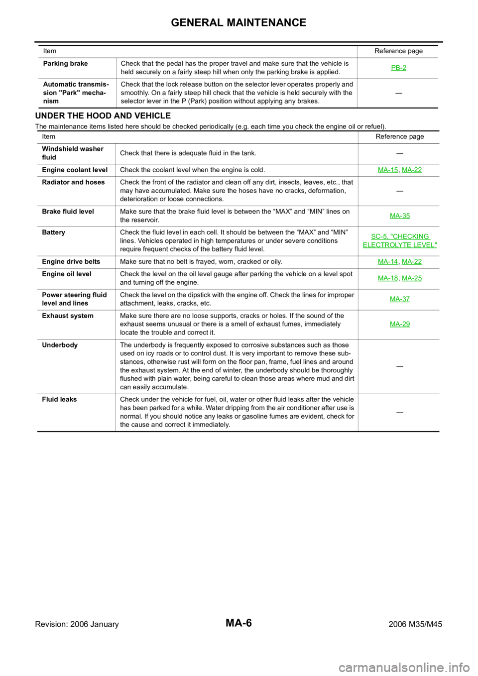
UNDER THE HOOD AND VEHICLE
The maintenance items listed here should be checked periodically (e.g. each time you check the engine oil or refuel). Parking brakeCheck that the pedal has the proper travel and make sure that the vehicle is
held securely on a fairly steep hill when only the parking brake is applied.PB-2
Automatic transmis-
sion "Park" mecha-
nismCheck that the lock release button on the selector lever operates properly and
smoothly. On a fairly steep hill check that the vehicle is held securely with the
selector lever in the P (Park) position without applying any brakes.— ItemReference page
ItemReference page
Windshield washer
fluidCheck that there is adequate fluid in the tank. —
Engine coolant levelCheck the coolant level when the engine is cold.MA-15
, MA-22
Radiator and hosesCheck the front of the radiator and clean off any dirt, insects, leaves, etc., that
may have accumulated. Make sure the hoses have no cracks, deformation,
deterioration or loose connections.—
Brake fluid levelMake sure that the brake fluid level is between the “MAX” and “MIN” lines on
the reservoir.MA-35
BatteryCheck the fluid level in each cell. It should be between the “MAX” and “MIN”
lines. Vehicles operated in high temperatures or under severe conditions
require frequent checks of the battery fluid level.SC-5, "
CHECKING
ELECTROLYTE LEVEL"
Engine drive beltsMake sure that no belt is frayed, worn, cracked or oily.MA-14, MA-22
Engine oil levelCheck the level on the oil level gauge after parking the vehicle on a level spot
and turning off the engine.MA-18, MA-25
Power steering fluid
level and linesCheck the level on the dipstick with the engine off. Check the lines for improper
attachment, leaks, cracks, etc.MA-37
Exhaust systemMake sure there are no loose supports, cracks or holes. If the sound of the
exhaust seems unusual or there is a smell of exhaust fumes, immediately
locate the trouble and correct it.MA-29
UnderbodyThe underbody is frequently exposed to corrosive substances such as those
used on icy roads or to control dust. It is very important to remove these sub-
stances, otherwise rust will form on the floor pan, frame, fuel lines and around
the exhaust system. At the end of winter, the underbody should be thoroughly
flushed with plain water, being careful to clean those areas where mud and dirt
can easily accumulate.—
Fluid leaksCheck under the vehicle for fuel, oil, water or other fluid leaks after the vehicle
has been parked for a while. Water dripping from the air conditioner after use is
normal. If you should notice any leaks or gasoline fumes are evident, check for
the cause and correct it immediately.—
Page 4792 of 5621
ENGINE MAINTENANCE (VQ35DE ENGINE)
MA-15
C
D
E
F
G
H
I
J
K
MA
B
MA
Revision: 2006 January2006 M35/M45
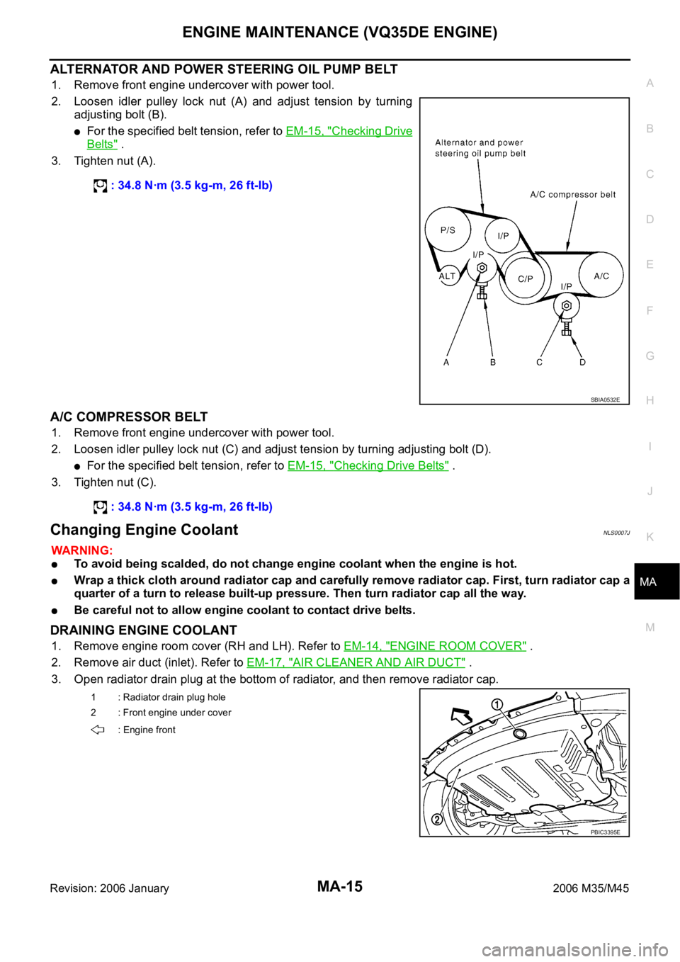
ALTERNATOR AND POWER STEERING OIL PUMP BELT
1. Remove front engine undercover with power tool.
2. Loosen idler pulley lock nut (A) and adjust tension by turning
adjusting bolt (B).
For the specified belt tension, refer to EM-15, "Checking Drive
Belts" .
3. Tighten nut (A).
A/C COMPRESSOR BELT
1. Remove front engine undercover with power tool.
2. Loosen idler pulley lock nut (C) and adjust tension by turning adjusting bolt (D).
For the specified belt tension, refer to EM-15, "Checking Drive Belts" .
3. Tighten nut (C).
Changing Engine CoolantNLS0007J
WAR NING :
To avoid being scalded, do not change engine coolant when the engine is hot.
Wrap a thick cloth around radiator cap and carefully remove radiator cap. First, turn radiator cap a
quarter of a turn to release built-up pressure. Then turn radiator cap all the way.
Be careful not to allow engine coolant to contact drive belts.
DRAINING ENGINE COOLANT
1. Remove engine room cover (RH and LH). Refer to EM-14, "ENGINE ROOM COVER" .
2. Remove air duct (inlet). Refer to EM-17, "
AIR CLEANER AND AIR DUCT" .
3. Open radiator drain plug at the bottom of radiator, and then remove radiator cap. : 34.8 Nꞏm (3.5 kg-m, 26 ft-lb)
SBIA0532E
: 34.8 Nꞏm (3.5 kg-m, 26 ft-lb)
1 : Radiator drain plug hole
2 : Front engine under cover
: Engine front
PBIC3395E
Page 4793 of 5621
MA-16
ENGINE MAINTENANCE (VQ35DE ENGINE)
Revision: 2006 January2006 M35/M45
When draining all of engine coolant in the system, open water drain plugs on cylinder block. Refer
to EM-124, "
DISASSEMBLY" .
4. Remove reservoir tank as necessary, and drain engine coolant and clean reservoir tank before installing.
5. Check drained engine coolant for contaminants such as rust, corrosion or discoloration.
If contaminated, flush the engine cooling system. Refer to CO-13, "
FLUSHING COOLING SYSTEM" .
REFILLING ENGINE COOLANT
1. Install reservoir tank if removed, and radiator drain plug.
CAUTION:
Be sure to clean drain plug and install with new O-ring.
If water drain plugs on cylinder block are removed, close and tighten them. Refer to EM-128,
"ASSEMBLY" .
2. Make sure that each hose clamp has been firmly tightened.
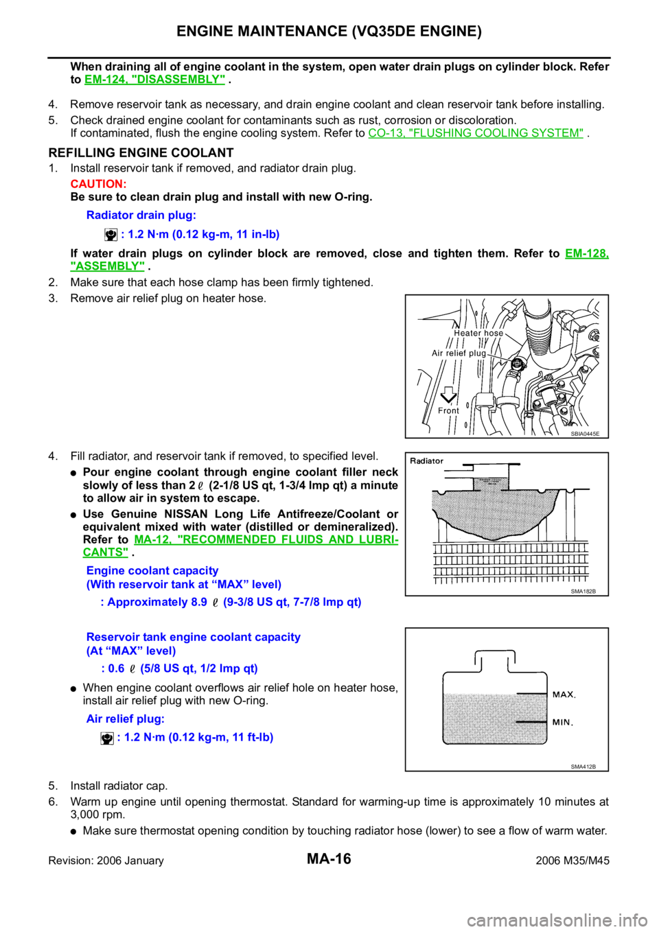
3. Remove air relief plug on heater hose.
4. Fill radiator, and reservoir tank if removed, to specified level.
Pour engine coolant through engine coolant filler neck
slowly of less than 2 (2-1/8 US qt, 1-3/4 lmp qt) a minute
to allow air in system to escape.
Use Genuine NISSAN Long Life Antifreeze/Coolant or
equivalent mixed with water (distilled or demineralized).
Refer to MA-12, "
RECOMMENDED FLUIDS AND LUBRI-
CANTS" .
When engine coolant overflows air relief hole on heater hose,
install air relief plug with new O-ring.
5. Install radiator cap.
6. Warm up engine until opening thermostat. Standard for warming-up time is approximately 10 minutes at
3,000 rpm.
Make sure thermostat opening condition by touching radiator hose (lower) to see a flow of warm water. Radiator drain plug:
: 1.2 Nꞏm (0.12 kg-m, 11 in-lb)
SBIA0445E
Engine coolant capacity
(With reservoir tank at “MAX” level)
: Approximately 8.9 (9-3/8 US qt, 7-7/8 lmp qt)
SMA182B
Reservoir tank engine coolant capacity
(At “MAX” level)
: 0.6 (5/8 US qt, 1/2 lmp qt)
Air relief plug:
: 1.2 Nꞏm (0.12 kg-m, 11 ft-lb)
SMA412B
Page 4794 of 5621
ENGINE MAINTENANCE (VQ35DE ENGINE)
MA-17
C
D
E
F
G
H
I
J
K
MA
B
MA
Revision: 2006 January2006 M35/M45
CAUTION:
Watch water temperature gauge so as not to overheat engine.
7. Stop the engine and cool down to less than approximately 50
C (122F).
Cool down using fan to reduce the time.
If necessary, refill radiator up to filler neck with engine coolant.
8. Refill reservoir tank to “MAX” level line with engine coolant.
9. Repeat steps 4 through 7 two or more times with radiator cap installed until engine coolant level no longer
drops.
10. Check cooling system for leaks with engine running.
11. Warm up the engine, and check for sound of engine coolant flow while running engine from idle up to
3,000 rpm with heater temperature controller set at several position between “COOL” and “WARM”.
Sound may be noticeable at heater unit.
12. Repeat step 11 three times.
13. If sound is heard, bleed air from cooling system by repeating step 4 through 7 until engine coolant level no
longer drops.
FLUSHING COOLING SYSTEM
1. Install reservoir tank if removed, and radiator drain plug.
CAUTION:
Be sure to clean drain plug and install with new O-ring.
If water drain plugs on cylinder block are removed, close and tighten them. Refer to EM-128,
"ASSEMBLY" .
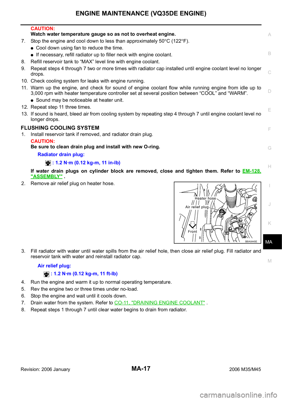
2. Remove air relief plug on heater hose.
3. Fill radiator with water until water spills from the air relief hole, then close air relief plug. Fill radiator and
reservoir tank with water and reinstall radiator cap.
4. Run the engine and warm it up to normal operating temperature.
5. Rev the engine two or three times under no-load.
6. Stop the engine and wait until it cools down.
7. Drain water from the system. Refer to CO-11, "
DRAINING ENGINE COOLANT" .
8. Repeat steps 1 through 7 until clear water begins to drain from radiator. Radiator drain plug:
: 1.2 Nꞏm (0.12 kg-m, 11 in-lb)
SBIA0445E
Air relief plug:
: 1.2 Nꞏm (0.12 kg-m, 11 ft-lb)