2006 INFINITI M35 tires
[x] Cancel search: tiresPage 5095 of 5621

RSU-14
RADIUS ROD
Revision: 2006 January2006 M35/M45
RADIUS RODPFP:55110
Removal and InstallationNES000JD
REMOVAL
1. Remove tire with a power tool.
2. Remove brake caliper with a power tool. Hang it in a place where it will not interfere with work. Refer to
BR-29, "
REAR DISC BRAKE" .
CAUTION:
Do not depressing brake pedal while brake caliper is removed.
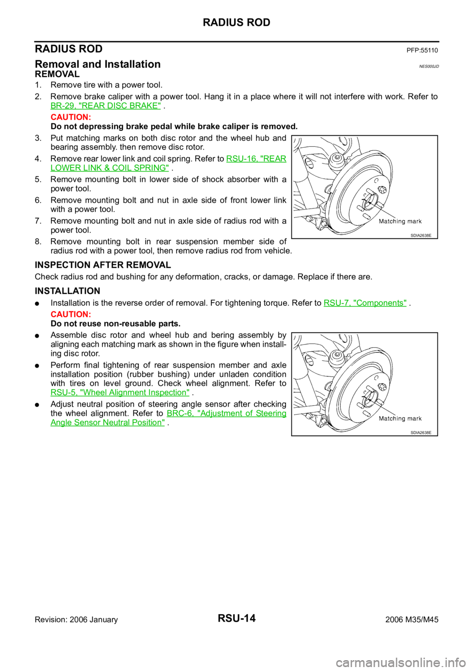
3. Put matching marks on both disc rotor and the wheel hub and
bearing assembly. then remove disc rotor.
4. Remove rear lower link and coil spring. Refer to RSU-16, "
REAR
LOWER LINK & COIL SPRING" .
5. Remove mounting bolt in lower side of shock absorber with a
power tool.
6. Remove mounting bolt and nut in axle side of front lower link
with a power tool.
7. Remove mounting bolt and nut in axle side of radius rod with a
power tool.
8. Remove mounting bolt in rear suspension member side of
radius rod with a power tool, then remove radius rod from vehicle.
INSPECTION AFTER REMOVAL
Check radius rod and bushing for any deformation, cracks, or damage. Replace if there are.
INSTALLATION
Installation is the reverse order of removal. For tightening torque. Refer to RSU-7, "Components" .
CAUTION:
Do not reuse non-reusable parts.
Assemble disc rotor and wheel hub and bering assembly by
aligning each matching mark as shown in the figure when install-
ing disc rotor.
Perform final tightening of rear suspension member and axle
installation position (rubber bushing) under unladen condition
with tires on level ground. Check wheel alignment. Refer to
RSU-5, "
Wheel Alignment Inspection" .
Adjust neutral position of steering angle sensor after checking
the wheel alignment. Refer to BRC-6, "
Adjustment of Steering
Angle Sensor Neutral Position" .
SDIA2638E
SDIA2638E
Page 5096 of 5621

FRONT LOWER LINK
RSU-15
C
D
F
G
H
I
J
K
L
MA
B
RSU
Revision: 2006 January2006 M35/M45
FRONT LOWER LINKPFP:55110
Removal and InstallationNES000JE
REMOVAL
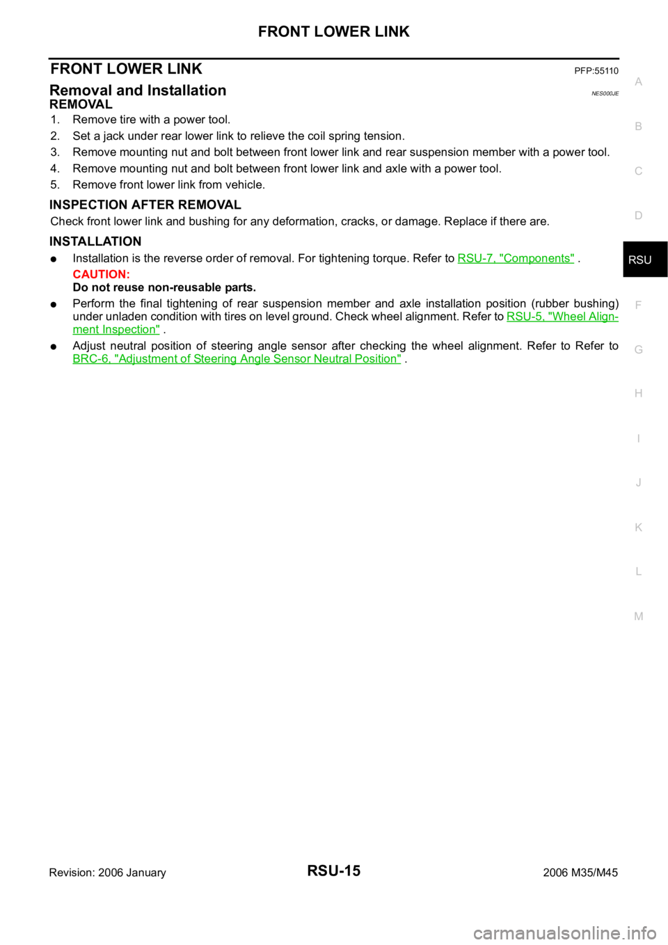
1. Remove tire with a power tool.
2. Set a jack under rear lower link to relieve the coil spring tension.
3. Remove mounting nut and bolt between front lower link and rear suspension member with a power tool.
4. Remove mounting nut and bolt between front lower link and axle with a power tool.
5. Remove front lower link from vehicle.
INSPECTION AFTER REMOVAL
Check front lower link and bushing for any deformation, cracks, or damage. Replace if there are.
INSTALLATION
Installation is the reverse order of removal. For tightening torque. Refer to RSU-7, "Components" .
CAUTION:
Do not reuse non-reusable parts.
Perform the final tightening of rear suspension member and axle installation position (rubber bushing)
under unladen condition with tires on level ground. Check wheel alignment. Refer to RSU-5, "
Wheel Align-
ment Inspection" .
Adjust neutral position of steering angle sensor after checking the wheel alignment. Refer to Refer to
BRC-6, "
Adjustment of Steering Angle Sensor Neutral Position" .
Page 5097 of 5621

RSU-16
REAR LOWER LINK & COIL SPRING
Revision: 2006 January2006 M35/M45
REAR LOWER LINK & COIL SPRINGPFP:551B0
Removal and InstallationNES000JF
REMOVAL
1. Remove tire with a power tool.
2. Set a jack under rear lower link to relieve the coil spring tension.
3. Loosen mounting bolt and nut of rear lower link inside of suspension member, and then remove mounting
bolt and nut inside of axle with a power tool.
4. Slowly lower jack, then remove upper seat, coil spring and rubber sheet from rear lower link.
5. Remove mounting bolt and nut inside of suspension member to remove rear lower link with a power tool.
INSPECTION AFTER REMOVAL
Check rear lower link, bushing and coil spring for deformation, cracks, and damage. Replace rear lower link
and coil spring if there are.
INSTALLATION
Installation is the reverse order of removal. For tightening torque. Refer to RSU-7, "Components" .
CAUTION:
Do not reuse non-reusable parts.
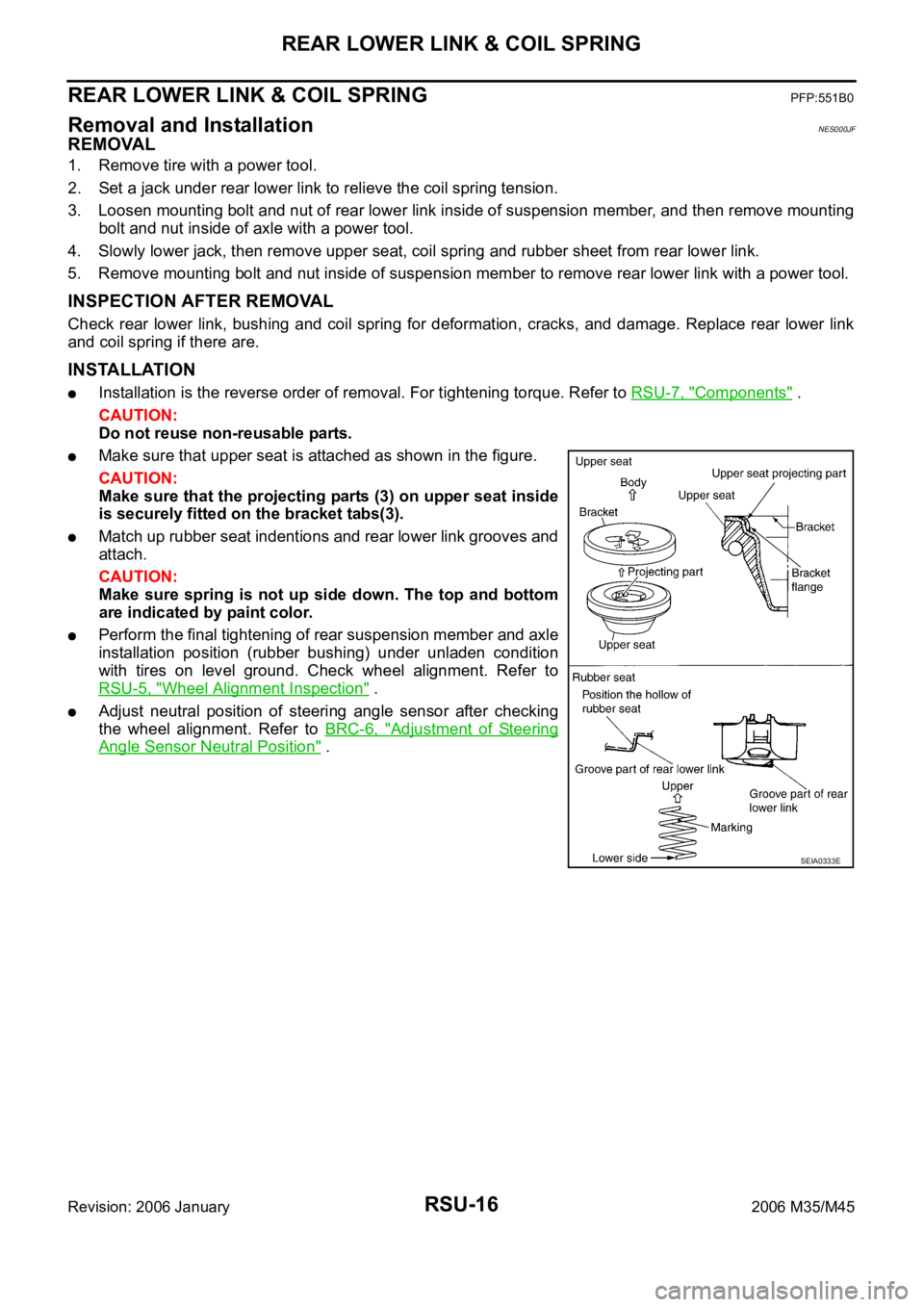
Make sure that upper seat is attached as shown in the figure.
CAUTION:
Make sure that the projecting parts (3) on upper seat inside
is securely fitted on the bracket tabs(3).
Match up rubber seat indentions and rear lower link grooves and
attach.
CAUTION:
Make sure spring is not up side down. The top and bottom
are indicated by paint color.
Perform the final tightening of rear suspension member and axle
installation position (rubber bushing) under unladen condition
with tires on level ground. Check wheel alignment. Refer to
RSU-5, "
Wheel Alignment Inspection" .
Adjust neutral position of steering angle sensor after checking
the wheel alignment. Refer to BRC-6, "
Adjustment of Steering
Angle Sensor Neutral Position" .
SEIA0333E
Page 5424 of 5621
![INFINITI M35 2006 Factory Service Manual TROUBLE DIAGNOSIS
STC-9
[EPS]
C
D
E
F
H
I
J
K
L
MA
B
STC
Revision: 2006 January2006 M35/M45
For Fast and Accurate Trouble DiagnosisNGS000E1
Check the following items with the vehicle stopped
Is air pr INFINITI M35 2006 Factory Service Manual TROUBLE DIAGNOSIS
STC-9
[EPS]
C
D
E
F
H
I
J
K
L
MA
B
STC
Revision: 2006 January2006 M35/M45
For Fast and Accurate Trouble DiagnosisNGS000E1
Check the following items with the vehicle stopped
Is air pr](/manual-img/42/57023/w960_57023-5423.png)
TROUBLE DIAGNOSIS
STC-9
[EPS]
C
D
E
F
H
I
J
K
L
MA
B
STC
Revision: 2006 January2006 M35/M45
For Fast and Accurate Trouble DiagnosisNGS000E1
Check the following items with the vehicle stopped
Is air pressure and size of tires proper?
Is the specified part used for the steering wheel?
Is control unit a genuine part?
Are there any fluid leakage from steering gear assembly, power steering oil pump, and hydraulic pipes,
etc? Refer to PS-8, "
POWER STEERING FLUID" .
Is the fluid level proper? Refer to PS-8, "POWER STEERING FLUID" .
Is the wheel alignment adjusted properly? Refer to FSU-19, "SERVICE DATA AND SPECIFICATIONS
(SDS)" (2WD), FSU-36, "SERVICE DATA AND SPECIFICATIONS (SDS)" (AWD).
Are there any damage or modification to suspension or body resulting in increased weight or altered
ground clearance?
Check each link installation condition of suspension and axle.
Check each connector connection condition.
Check the following items while driving the vehicle
Check conditions when the malfunction occurred (5W 1H).
Is the engine condition normal?
Basic InspectionNGS000E2
POWER SUPPLY CIRCUIT TERMINAL LOOSENESS AND BATTERY
Check battery terminals for looseness on both positive and negative ones and ground connection. Also make
sure that battery voltage does not drop.
Inspection: Power Steering Control Unit Power Supply Circuit and GroundNGS000E3
1. CHECK POWER STEERING CONTROL UNIT CONNECTOR
Turn ignition switch OFF, disconnect power steering control unit harness connector, and check terminal for
deformation, disconnection, looseness, etc.
OK or NG
OK >> GO TO 2.
NG >> Connector terminal connection is loose, damaged, open, or shorted. Repair or replace the termi-
nal.
2. CHECK POWER STEERING CONTROL UNIT GROUND CIRCUIT
Disconnect power steering control unit harness connector M8, and
then check continuity between power steering control unit harness
connector M8 and ground.
OK or NG
OK >> GO TO 3.
NG >> Ground circuit open or shorted. Repair or replace any
inoperative parts. Terminal 2 – Ground : Continuity exist.
SGIA1231E
Page 5442 of 5621
![INFINITI M35 2006 Factory Service Manual TROUBLE DIAGNOSIS
STC-27
[RAS]
C
D
E
F
H
I
J
K
L
MA
B
STC
Revision: 2006 January2006 M35/M45
STANDARD BY CONSULT-II
CAUTION:
The output signal indicates the RAS control unit calculation data. The norm INFINITI M35 2006 Factory Service Manual TROUBLE DIAGNOSIS
STC-27
[RAS]
C
D
E
F
H
I
J
K
L
MA
B
STC
Revision: 2006 January2006 M35/M45
STANDARD BY CONSULT-II
CAUTION:
The output signal indicates the RAS control unit calculation data. The norm](/manual-img/42/57023/w960_57023-5441.png)
TROUBLE DIAGNOSIS
STC-27
[RAS]
C
D
E
F
H
I
J
K
L
MA
B
STC
Revision: 2006 January2006 M35/M45
STANDARD BY CONSULT-II
CAUTION:
The output signal indicates the RAS control unit calculation data. The normal values will be displayed
even in the event that the output circuit (harness) is open.
Monitor itemDATA MONITOR
Malfunction inspection
checklist
Condition Reference values
VHCL SPEED SE (km/h)Ignition switch ON or engine
running Almost in accordance with the speed-
ometer display. It is not a malfunction,
through it might not be corresponding
just after ignition switch is turned ON.STC-38, "
Inspection 4:
Vehicle Speed Signal"
STEERING ANG ()Turning steering wheel clock-
wise or counterclockwise.Displays the angle when the steering
wheel turns from the neutral positionSTC-38, "
Inspection 5:
Steering Angle Signal
Malfunction"
ENGINE SPEED (rpm) Engine runningAlmost in accordance with tachometer
displaySTC-43, "
Inspection 8:
Engine Speed Signal
Malfunction"
POWER STR SOL (A)Accelerate the vehicle from 0
to 100 km/h (0 to 62 MPH)0 km/h (0 MPH): Approx. 1.10 A
100 km/h (62 MPH): Approx. 0.54 ASTC-46, "Diagnosis
Chart by Symptom 2"
RR ST ANG-MAI (V)
Perform the ACTIVE TEST
and stroke the actuator (with
tires off the ground)Neutral: Approx. 2.4 V
Turn steering wheel to right for full
stroke: Approx. 4.4 V
Turn steering wheel to left for full
stroke: Approx. 0.4 VSTC-40, "Inspection 6:
Rear Main Signal and
Rear Sub Signal Mal-
function"RR ST ANG- SUB (V)
RR ST ANG-VOL (V)
Ignition switch ON or engine
runningApprox. 5 VSTC-40, "
Inspection 6:
Rear Main Signal and
Rear Sub Signal Mal-
function"
C/U VOLTAGE (V) Battery voltage (Approx. 12 V)STC-35, "
Inspection 1:
RAS Control Unit Mal-
function"
MOTOR VOLTAGE (V) Battery voltage (Approx. 12V)STC-35, "
Inspection 2:
Motor Power Supply
System"
MOTOR CURRENT (A)Perform the ACTIVE TEST
and stroke the actuator.It is normal when there is the current
output at strokeSTC-35, "
Inspection 2:
Motor Power Supply
System"
MTR CRNT OPE (A)Turning steering wheel clock-
wise or counterclockwise
while ignition switch is ON or
running the engineNeutral (Steering force is zero and
straight-ahead position): Approx. 0 A
The value is changed according to
steering left or right STC-37, "
Inspection 3:
RAS Motor Output
Malfunction"
STOP LAMP SWDepressing or releasing brake
pedalBrake pedal depressed: ONSTC-44, "
Inspection
10: Stop Lamp Switch
Harness"Brake pedal not depressed: OFF
RAS RELAY
Ignition switch ON or engine
runningIgnition switch ON: ONSTC-35, "
Inspection 2:
Motor Power Supply
System"
FAIL SAFE Not activatedSelf-diagnosis and
suspect system
inspection on DATA
MONITOR
WARNING LAMP (ON/OFF)RAS warning lamp ON: ON
RAS warning lamp OFF: OFFWarning lamp circuit
inspection
Page 5447 of 5621
![INFINITI M35 2006 Factory Service Manual STC-32
[RAS]
TROUBLE DIAGNOSIS
Revision: 2006 January2006 M35/M45
For Fast and Accurate Trouble DiagnosisNGS000EN
Check the following items with the vehicle stopped
Is air pressure and size of tires p INFINITI M35 2006 Factory Service Manual STC-32
[RAS]
TROUBLE DIAGNOSIS
Revision: 2006 January2006 M35/M45
For Fast and Accurate Trouble DiagnosisNGS000EN
Check the following items with the vehicle stopped
Is air pressure and size of tires p](/manual-img/42/57023/w960_57023-5446.png)
STC-32
[RAS]
TROUBLE DIAGNOSIS
Revision: 2006 January2006 M35/M45
For Fast and Accurate Trouble DiagnosisNGS000EN
Check the following items with the vehicle stopped
Is air pressure and size of tires proper?
Is the specified part used for the steering wheel?
Is control unit a genuine part?
Are there any fluid leakage from steering gear assembly, power steering oil pump, and hydraulic pipes,
etc? Refer to PS-8, "
POWER STEERING FLUID" .
Is the fluid level proper? Refer to PS-8, "POWER STEERING FLUID" .
Is the wheel alignment is adjusted properly? Refer to FSU-19, "SERVICE DATA AND SPECIFICATIONS
(SDS)" (2WD), FSU-36, "SERVICE DATA AND SPECIFICATIONS (SDS)" (AWD).
Are there any damage or modification to suspension or body resulting in increased weight or altered
ground clearance?
Check each link installation condition of suspension and axle.
Is the battery voltage proper?
Check each connector connection condition.
Check the following items while driving the vehicle
Conditions when the error occurred (5W 1H).
Is the engine is normal?
Basic InspectionNGS000EO
BASIC INSPECTION 1: POWER SUPPLY CIRCUIT TERMINAL LOOSENESS AND BATTERY
Check battery terminals for looseness on both positive and negative ones and ground connection. Also make
sure that battery voltage does not drop.
BASIC INSPECTION 2: RAS WARNING LAMP INSPECTION
1. Make sure RAS warning lamp turns on when ignition switch is turned ON.
If it does not turn on, refer to STC-33, "Trouble Diagnosis Chart" .
2. Make sure that RAS warning lamp turns off when the engine is started after ignition switch is turned ON. If
it does not turn off, perform self-diagnosis. Refer to STC-28, "
SELF-DIAG RESULT MODE" .
3. Always erase DTC memory after completing self-diagnosis. Refer to STC-29, "
How to Erase Self-Diag-
nostic Results" .
BASIC INSPECTION 3: RAS CONTROL UNIT POWER SUPPLY CIRCUIT AND GROUND CIR-
CUIT INSPECTION
1. CHECK RAS CONTROL UNIT CONNECTOR
Turn ignition switch OFF, disconnect RAS control unit harness connector, and check terminal for deformation,
disconnection, looseness, etc.
OK or NG
OK >> GO TO 2.
NG >> Poor connection of connector terminal. Repair or replace the terminal.
2. CHECK RAS CONTROL UNIT GROUND CIRCUIT
1. Disconnect RAS control unit harness connector B127, and then
check continuity between RAS control unit harness connector
B127 and ground.
OK or NG
OK >> GO TO 3.
NG >> Ground circuit open or shorted. Repair or replace any
inoperative parts. Terminal 34 – Ground : Continuity
SGIA1244E
Page 5469 of 5621

TF-4
PRECAUTIONS
Revision: 2006 January2006 M35/M45
Service Notice or PrecautionsNDS000D5
Do not reuse transfer fluid, once it has been drained.
Check the fluid level or replace the fluid only with the vehicle parked on level ground.
During removal or installation, keep inside of transfer clear of dust or dirt.
Replace all tires at the same time. Always use tires of the proper size and the same brand and pattern.
Fitting improper size and unusual wear tires applies excessive force to vehicle mechanism and can cause
longitudinal vibration.
Disassembly should be done in a clean work area, it is preferable to work in dustproof area.
Before proceeding with disassembly, thoroughly clean the transfer. It is important to prevent the internal
parts from becoming contaminated by dirt or other foreign matter.
All parts should be carefully cleaned with a general purpose, non-flammable solvent before inspection or
reassembly.
Check for the correct installation status prior to removal or disassembly. If matching marks are required,
be certain they do not interfere with the function of the parts when applied.
Check appearance of the disassembled parts for damage, deformation, and unusual wear. Replace them
with a new ones if necessary.
Gaskets, seals and O-rings should be replaced any time when the transfer is disassembled.
In principle, tighten bolts or nuts gradually in several steps working diagonally from inside to outside. If
tightening sequence is specified, use it.
Observe the specified torque when assembling.
Clean and flush the parts sufficiently and blow-dry them.
Be careful not to damage sliding surfaces and mating surfaces.
Clean innerparts with lint-free cloth or towels. Do not use cotton work gloves and rags to prevent adhering
fibers.
Page 5475 of 5621

TF-10
AWD SYSTEM
Revision: 2006 January2006 M35/M45
AWD SYSTEMPFP:41650
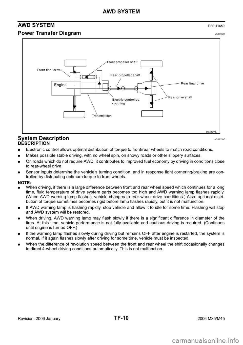
Power Transfer DiagramNDS000DB
System DescriptionNDS000DC
DESCRIPTION
Electronic control allows optimal distribution of torque to front/rear wheels to match road conditions.
Makes possible stable driving, with no wheel spin, on snowy roads or other slippery surfaces.
On roads which do not require AWD, it contributes to improved fuel economy by driving in conditions close
to rear-wheel drive.
Sensor inputs determine the vehicle's turning condition, and in response tight cornering/braking are con-
trolled by distributing optimum torque to front wheels.
NOTE:
When driving, if there is a large difference between front and rear wheel speed which continues for a long
time, fluid temperature of drive system parts becomes too high and AWD warning lamp flashes rapidly.
(When AWD warning lamp flashes, vehicle changes to rear-wheel drive conditions.) Also, optional distri-
bution of torque sometimes becomes rigid before lamp flashes rapidly, but it is not malfunction.
If AWD warning lamp is flashing rapidly, stop vehicle and allow it to idle for some time. Flashing will stop
and AWD system will be restored.
When driving, AWD warning lamp may flash slowly if there is a significant difference in diameter of the
tires. At this time, vehicle performance is not fully available and cautious driving is required. (Continues
until engine is turned OFF.)
If the warning lamp flashes slowly during driving but remains OFF after engine is restarted, the system is
normal. If it again flashes slowly after driving for some time, vehicle must be inspected.
When the difference of revolution speed between the front and rear wheel the shift occasionally changes
to direct 4-wheel driving conditions automatically. This is not malfunction.
SDIA1611E