Page 4244 of 4462
SE-106
REAR SEAT
Revision: 2006 December 2006 FX35/FX45
1. Headrest (side) 2. Headrest holder (free) 3. Headrest holder (locked)
4. Seatback trim (RH) 5. Seatback pad (RH) 6. Seatback frame (RH)
7. Nut 8. Seat hinge cover (RH) 9. Screw
10. Reclining lever (RH) 11. Reclining device outer cover (RH) 12. Reclining device inner cover (RH)
13. Bolt 14. Seatback garnish (RH) 15. Trunk net hook
16. Clip (C101) 17. Headrest (center) 18. Seatback trim (LH)
19. Seatback pad (LH) 20. Seatback frame (LH) 21. Seatback garnish (LH)
22. Armrest bracket cover 23. Armrest bracket 24. Armrest
25. Reclining device inner cover (LH) 26. Reclining device outer cover (LH) 27. Reclining lever (LH)
28. Seat hinge cover (LH) 29. Seat cushion trim 30. Seat cushion pad
31. Cup holder bracket 32. Cup holder
Page 4245 of 4462
REAR SEAT SE-107
C
D E
F
G H
J
K L
M A
B
SE
Revision: 2006 December 2006 FX35/FX45
REMOVAL
1. Pull the lock at the front bottom of the seat cushion forward (1 for each side), and pull the seat cushion upward to release the
wire from the plastic hook, then pull the seat cushion forward to
remove.
2. Remove the seatback mounting nuts.
3. Remove the seatback mounting bolt and nut. Remove the remote control wire.
INSTALLATION
Install in the reverse order of removal.
NOTE:
After rear wheel house finisher assembly is remove the seatback is installed. Refer to EI-44, "
Removal and
Installation" .
REMOVAL OF SEAT CUSHION TRIM AND PAD
1. Remove the cup holder in the back of the seat cushion.
2. Removal the hog rings to separate the trim and pad.
PIIA6034E
PIIA6035E
PIIA6036E
PIIA4985E
Page 4284 of 4462

SRS-36
TROUBLE DIAGNOSIS
Revision: 2006 December 2006 FX35/FX45
Trouble Diagnosis: “AIR BAG” Warning Lamp Does Not Turn OFFNHS0007J
DIAGNOSTIC PROCEDURE 7
1. CHECK THE DEPLOYMENT OF AIR BAG MODULE
Is air bag module deployed?
YES or NO
YES >> Refer to SRS-50, "COLLISION DIAGNOSIS" .
NO >> GO TO 2.
2. CHECK THE AIR BAG FUSE
Check 10A fuse [No. 13, located in fuse block (J/B)].
Refer to PG-3, "
POWER SUPPLY ROUTING CIRCUIT" .
OK or NG
OK >> GO TO 4.
NG >> GO TO 3.
3. CHECK AIR BAG FUSE AGAIN
Replace “AIR BAG” fuse and turn ignition switch ON.
Does the
“AIR BAG” fuse blow again?
YES >> Repair or replace main harness.
NO >> INSPECTION END
4. CHECK DIAGNOSIS SENSOR UNIT
Connect CONSULT-II and touch “START”.
Is “AIR BAG” displayed on CONSULT-II?
YES or NO
YES >> GO TO 5.
NO >> Visually check the wiring harness connection of diagno- sis sensor unit. If the harness connection check result is
OK, replace diagnosis sensor unit.
5. CHECK HARNESS CONNECTION
Is harness connection between warning lamp and diagnosis sensor unit OK?
OK or NG
OK >> Replace diagnosis sensor unit.
NG >> Connect “AIR BAG” warning lamp and diagnosis sensor unit connector properly. If “AIR BAG” warning lamp still does not go off, replace harness.
BCIA0030E
Page 4285 of 4462
TROUBLE DIAGNOSIS SRS-37
C
D E
F
G
I
J
K L
M A
B
SRS
Revision: 2006 December 2006 FX35/FX45
Trouble Diagnosis: “AIR BAG” Warning Lamp Does Not Turn ONNHS0007K
DIAGNOSTIC PROCEDURE 8
1. CHECK METER FUSE
Check 10A fuse [No. 14, located in fuse block (J/B)].
Refer to PG-3, "
POWER SUPPLY ROUTING CIRCUIT" .
OK or NG
OK >> GO TO 3.
NG >> GO TO 2.
2. CHECK METER FUSE AGAIN
Replace 10A fuse [No. 14, located in fuse block (J/B)] and turn ignition switch ON.
Does the meter fuse blow again?
YES >> Repair or replace the related harness.
NO >> INSPECTION END
3. CHECK HARNESS CONNECTION BETWEEN DIAGNOSIS SENSOR UNIT AND COMBINATION
METER
Disconnect diagnosis sensor unit connector and turn ignition switch ON.
Does “AIR BAG” warning lamp turn on?
YES or NO
YES >> Replace diagnosis sensor unit.
NO >> Replace combination meter assembly.
Page 4286 of 4462
SRS-38
DRIVER AIR BAG MODULE
Revision: 2006 December 2006 FX35/FX45
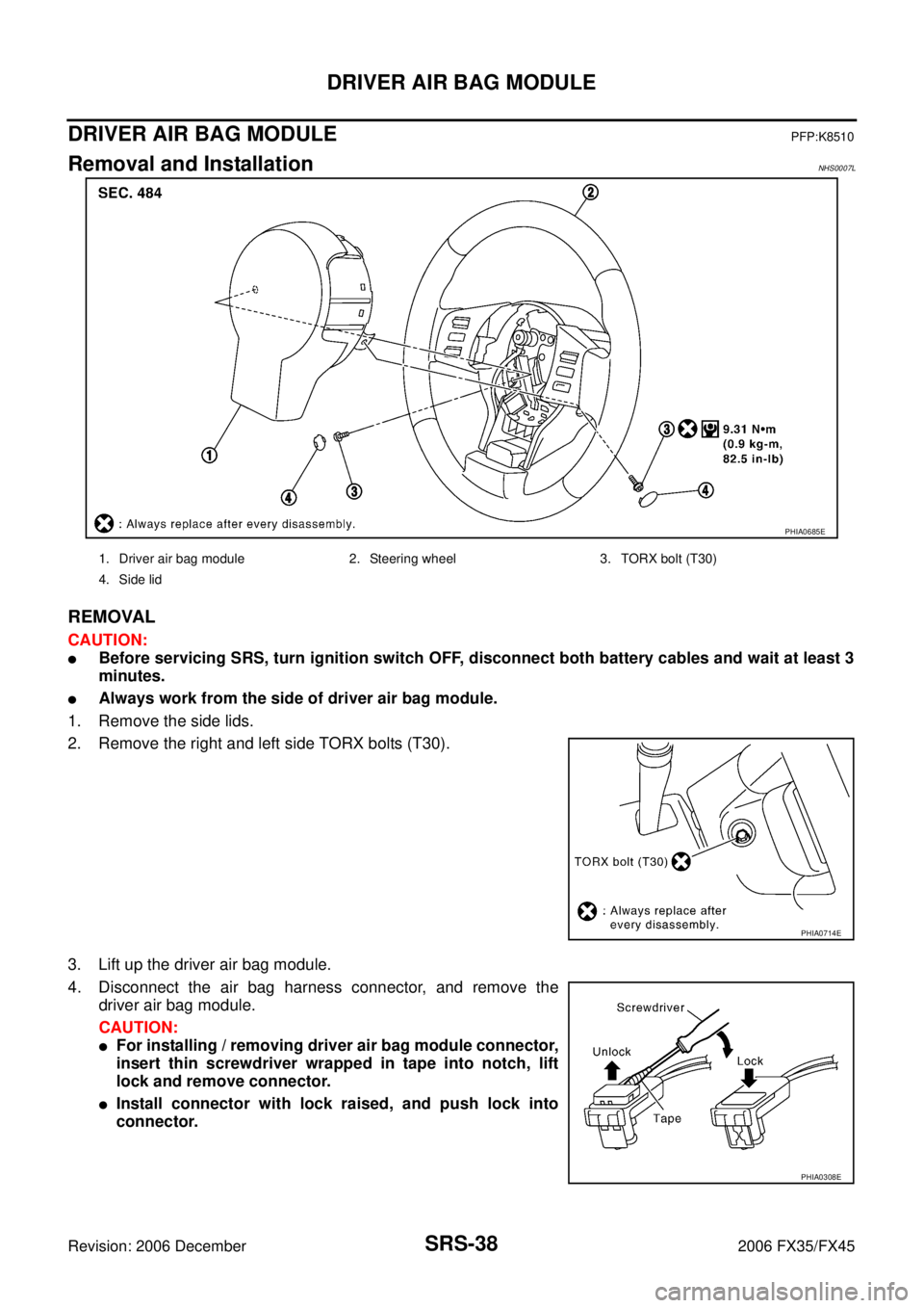
DRIVER AIR BAG MODULEPFP:K8510
Removal and InstallationNHS0007L
REMOVAL
CAUTION:
�Before servicing SRS, turn ignition switch OFF, disconnect both battery cables and wait at least 3
minutes.
�Always work from the side of driver air bag module.
1. Remove the side lids.
2. Remove the right and left side TORX bolts (T30).
3. Lift up the driver air bag module.
4. Disconnect the air bag harness connector, and remove the driver air bag module.
CAUTION:
�For installing / removing driver air bag module connector,
insert thin screwdriver wrapped in tape into notch, lift
lock and remove connector.
�Install connector with lock raised, and push lock into
connector.
PHIA0685E
1. Driver air bag module 2. Steering wheel 3. TORX bolt (T30)
4. Side lid
PHIA0714E
PHIA0308E
Page 4289 of 4462
SPIRAL CABLE SRS-41
C
D E
F
G
I
J
K L
M A
B
SRS
Revision: 2006 December 2006 FX35/FX45
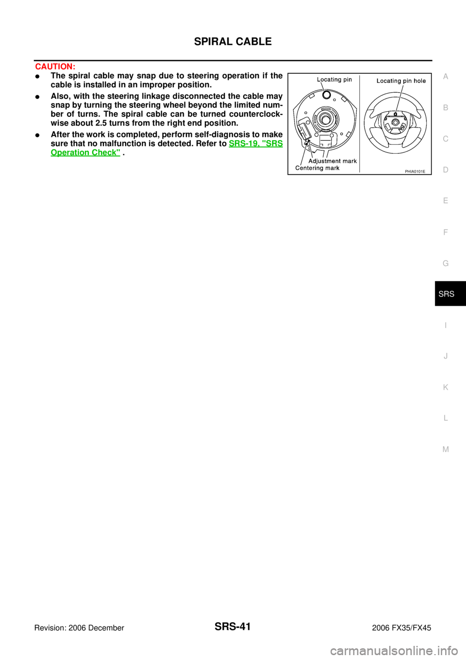
CAUTION:
�The spiral cable may snap due to steering operation if the
cable is installed in an improper position.
�Also, with the steering linkage disconnected the cable may
snap by turning the steering wheel beyond the limited num-
ber of turns. The spiral cable can be turned counterclock-
wise about 2.5 turns from the right end position.
�After the work is completed, perform self-diagnosis to make
sure that no malfunction is detected. Refer to SRS-19, "
SRS
Operation Check" .
PHIA0101E
Page 4309 of 4462
PREPARATION TF-7
C E F
G H
I
J
K L
M A
B
TF
Revision: 2006 December 2006 FX35/FX45
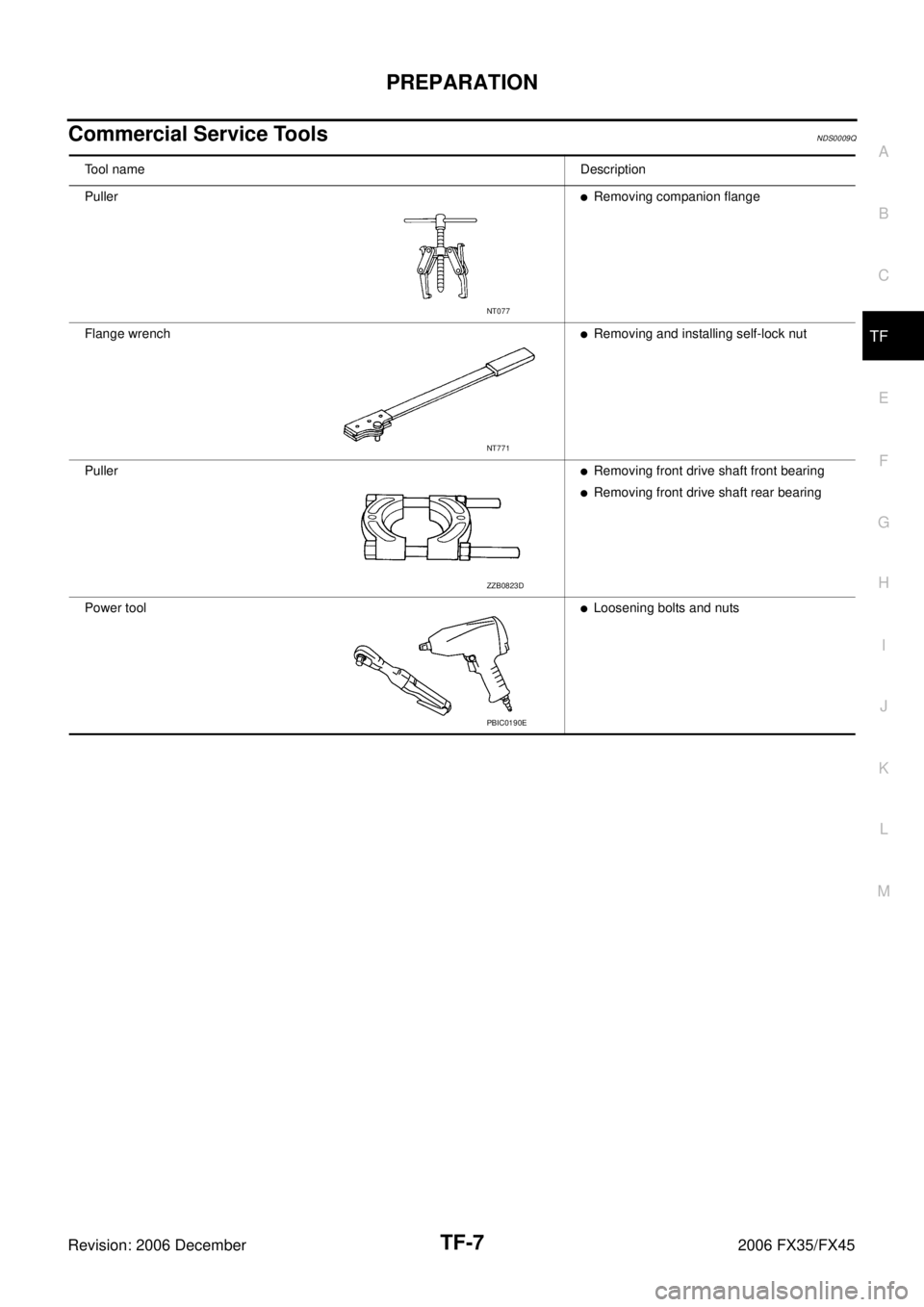
Commercial Service ToolsNDS0009Q
Tool name Description
Puller
�Removing companion flange
Flange wrench
�Removing and installing self-lock nut
Puller
�Removing front drive shaft front bearing
�Removing front drive shaft rear bearing
Power tool
�Loosening bolts and nuts
NT077
NT771
ZZB0823D
PBIC0190E
Page 4326 of 4462

TF-24
TROUBLE DIAGNOSIS
Revision: 2006 December 2006 FX35/FX45
DATA MONITOR MODE
Operation Procedure
1. Perform “CONSULT-II Start Procedure”. Refer to GI-38, "CONSULT-II Start Procedure" .
2. Touch “DATA MONITOR”.
3. Select from “SELECT MONITOR ITEM”, screen of data monitor mode is displayed. NOTE:
When malfunction is detected, CONSULT-II performs REAL-TIME DIAGNOSIS.
Also, any malfunction detected while in this mode will be displayed at real time.
Display Item List
× : Standard –: Not applicable
Monitored item (Unit) Monitor item selection
Remarks
ECU INPUT
SIGNALS MAIN
SIGNALS SELECTION
FROM MENU
FR RH SENSOR [km/h] or [mph] ××× Wheel speed calculated by front wheel
sensor RH signal is displayed.
FR LH SENSOR [km/h] or [mph] ××× Wheel speed calculated by front wheel
sensor LH signal is displayed.
RR RH SENSOR [km/h] or [mph] ××× Wheel speed calculated by rear wheel
sensor RH signal is displayed.
RR LH SENSOR [km/h] or [mph] ××× Wheel speed calculated by rear wheel
sensor LH signal is displayed.
BATTERY VOLT [V] – – ×Power supply voltage for AWD control unit
THRTL POS SEN [%] – – ×Throttle opening status is displayed.
ETS SOLENOID [A] – – × Monitored value of current at AWD sole-
noid
STOP LAMP SW [ON/OFF] – – × Stop lamp switch signal status via CAN
communication line is displayed.
ENG SPEED SIG [RUN/STOP] – – ×Engine status is displayed.
ETS ACTUATOR [ON/OFF] – – × Operating condition of AWD actuator relay
(integrated in AWD control unit) is dis-
played.
4WD WARN LAMP [ON/OFF] – – × Control status of AWD warning lamp is dis-
played.
4WD MODE SW [AUTO] – – × AWD lock switch is not equipped, but dis-
played.
4WD MODE MON [AUTO] – – ×Control status of AWD is displayed.
DIS-TIRE MONI [mm] – – × Improper size tire installed condition is dis-
played.
P BRAKE SW [ON/OFF] – – × Parking switch signal status via CAN com-
munication line is displayed.
Voltage [V] – – × The value measured by the voltage probe
is displayed.
Frequency [Hz] – – ×
The value measured by the pulse probe is
displayed.
DUTY-HI (high) [%] – –
×
DUTY-LOW (low) [%] – – ×
PLS WIDTH-HI [msec] – – ×
PLS WIDTH-LOW [msec] – – ×
 2. Headrest holder (free) 3. Headrest holder (locked)
4. Seatback trim (RH) 5. Seatback pad (RH) 6. Seatback frame (RH)
7. N")
, and pull the")