Page 4328 of 4462

TF-26
TROUBLE DIAGNOSIS FOR SYSTEM
Revision: 2006 December 2006 FX35/FX45
TROUBLE DIAGNOSIS FOR SYSTEMPFP:00000
Power Supply Circuit for AWD Control UnitNDS000A6
CONSULT-II REFERENCE VALUE IN DATA MONITOR MODE
Data are reference value.
DIAGNOSTIC PROCEDURE
1. CHECK POWER SUPPLY
1. Turn ignition switch “OFF”.
2. Disconnect AWD control unit harness connector.
3. Turn ignition switch “ON”. (Do not start engine.)
4. Check voltage between AWD control unit harness connector ter- minals and ground.
5. Turn ignition switch “OFF”.
6. Check voltage between AWD control unit harness connector ter- minals and ground.
OK or NG
OK >> GO TO 2.
NG >> Check the following. If any items are damaged, repair or replace damaged parts.
�10A fuse [No. 12 or 21, located in the fuse block (J/B)]
�Harness for short or open between battery and AWD control unit harness connector terminal 9
�Harness for short or open between ignition switch and AWD control unit harness connector ter-
minal 7
�Ignition switch. Refer to PG-3, "POWER SUPPLY ROUTING CIRCUIT" .
Monitored item [Unit] Condition Display value (Approx.)
BATTERY VOLT [V] Ignition switch: ON Battery voltage
Connector Terminal Voltage (Approx.)
M92 7 - Ground
Battery voltage
9 - Ground
SDIA2319E
Connector Terminal Voltage (Approx.)
M92 7 - Ground 0V
9 - Ground Battery voltage
SDIA2320E
Page 4331 of 4462

TROUBLE DIAGNOSIS FOR SYSTEM TF-29
C E F
G H
I
J
K L
M A
B
TF
Revision: 2006 December 2006 FX35/FX45
1. CHECK AWD SOLENOID SIGNAL
With CONSULT-II
1. Start engine.
2. Select “DATA MONITOR” mode for “ALL MODE AWD/4WD” with CONSULT-II.
3. Read out the value of “ETS SOLENOID”.
*: The values are changed by throttle opening and engine speed.
OK or NG
OK >> GO TO 6.
NG >> GO TO 2.
2. CHECK POWER SUPPLY
1. Turn ignition switch “OFF”.
2. Disconnect AWD control unit harness connector.
3. Turn ignition switch “ON”. (Do not start engine.)
4. Check voltage between AWD control unit harness connector ter- minal 9 and ground.
OK or NG
OK >> GO TO 3.
NG >> Check the following. If any items are damaged, repair or replace damaged parts.
�10A fuse [No. 21, located in the fuse block (J/B)]
�Harness for short or open between battery and AWD
control unit harness connector terminal 9
3. CHECK AWD SOLENOID CIRCUIT
1. Turn ignition switch “OFF”.
2. Disconnect AWD control unit harness connector.
3. Check resistance between AWD control unit harness connector terminals 1 and 2.
OK or NG
OK >> GO TO 6.
NG >> GO TO 4.
Condition Display value
Engine running At idle speed Approx. 0.000A
When depressing accelerator
pedal Approx. 0.000 - 2.400A*
SDIA1885E
Connector Terminal Voltage (Approx.)
M92 9 - Ground Battery voltage
SDIA1884E
Connector Terminal Resistance (Approx.)M92 1 - 2 (Ground) 2.45 Ω
SDIA1928E
Page 4336 of 4462

TF-34
TROUBLE DIAGNOSIS FOR SYMPTOMS
Revision: 2006 December 2006 FX35/FX45
2. CHECK AWD CONTROL UNIT POWER SUPPLY CIRCUIT
1. Turn ignition switch “OFF”.
2. Disconnect AWD control unit harness connector.
3. Turn ignition switch “ON”. (Do not start engine.)
4. Check voltage between AWD control unit harness connector ter- minals and ground.
5. Turn ignition switch “OFF”.
6. Check voltage between AWD control unit harness connector ter- minals and ground.
OK or NG
OK >> GO TO 3.
NG >> Check the following. If any items are damaged, repair or
replace damaged parts.
�10A fuse [No. 12 or 21, located in the fuse block (J/B)]
�Harness for short or open between battery and AWD control unit harness connector terminal 9
�Harness for short or open between ignition switch and AWD control unit harness connector ter-
minal 7
�Ignition switch. Refer to PG-3, "POWER SUPPLY ROUTING CIRCUIT" .
3. CHECK AWD CONTROL UNIT GROUND CIRCUIT
1. Turn ignition switch “OFF”.
2. Disconnect AWD control unit harness connector.
3. Check continuity between AWD control unit harness connector M92 terminals 10, 11 and ground.
Also check harness for short to ground and short to power.
OK or NG
OK >> GO TO 4.
NG >> Repair open circuit or short to ground or short to power in harness or connectors.
Connector Terminal Voltage (Approx.)
M92 7 - Ground
Battery voltage
9 - Ground
SDIA2319E
Connector Terminal Voltage (Approx.)
M92 7 - Ground 0V
9 - Ground Battery voltage
SDIA2320E
Continuity should exist.
SDIA1883E
Page 4343 of 4462
REAR OIL SEAL TF-41
C E F
G H
I
J
K L
M A
B
TF
Revision: 2006 December 2006 FX35/FX45
REAR OIL SEALPFP:33140
Removal and InstallationNDS000AL
REMOVAL
1. Remove the rear propeller shaft. Refer to PR-7, "REAR PROPELLER SHAFT" .
2. Remove self-lock nut of companion flange using the flange wrench.
3. Put matching mark on the end of the mainshaft. The mark should be in line with the mark on the companion flange.
CAUTION:
For matching mark, use paint. Do not damage mainshaft.
4. Remove the companion flange using a puller. CAUTION:
Be careful not to damage the companion flange.
5. Remove the rear oil seal using a puller. CAUTION:
Be careful not to damage the rear case.
SDIA2454E
SDIA2378E
SDIA1785E
Tool number : KV381054S0 (J-34286)
SDIA1786E
Page 4344 of 4462
TF-42
REAR OIL SEAL
Revision: 2006 December 2006 FX35/FX45
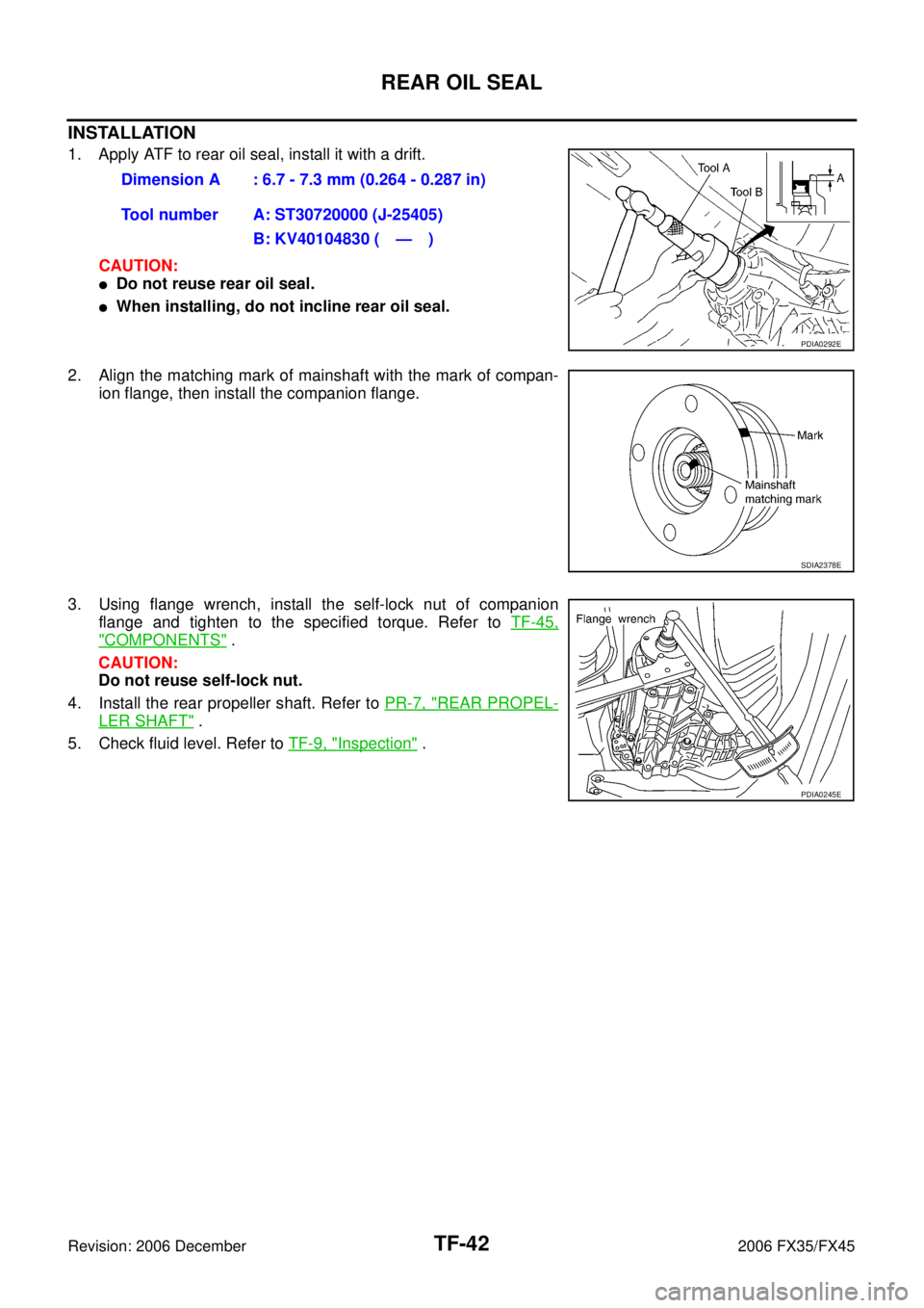
INSTALLATION
1. Apply ATF to rear oil seal, install it with a drift. CAUTION:
�Do not reuse rear oil seal.
�When installing, do not incline rear oil seal.
2. Align the matching mark of mainshaft with the mark of compan- ion flange, then install the companion flange.
3. Using flange wrench, install the self-lock nut of companion flange and tighten to the specified torque. Refer to TF-45,
"COMPONENTS" .
CAUTION:
Do not reuse self-lock nut.
4. Install the rear propeller shaft. Refer to PR-7, "
REAR PROPEL-
LER SHAFT" .
5. Check fluid level. Refer to TF-9, "
Inspection" .
Dimension A : 6.7 - 7.3 mm (0.264 - 0.287 in)
Tool number A: ST30720000 (J-25405) B: KV40104830 ( — )
PDIA0292E
SDIA2378E
PDIA0245E
Page 4347 of 4462
TRANSFER ASSEMBLY TF-45
C E F
G H
I
J
K L
M A
B
TF
Revision: 2006 December 2006 FX35/FX45
Disassembly and AssemblyNDS000AO
COMPONENTS
1. Drive chain 2. Front drive shaft rear bearing 3. Front drive shaft
4. Front drive shaft front bearing 5. Sprocket 6. Mainshaft
7. Needle bearing 8. Snap ring 9. Mainshaft bearing
10. Front case 11. Front oil seal 12. Mainshaft oil seal
13. Oil cover 14. Temperature sensor 15. Electric controlled coupling
16. Spacer 17. Snap ring 18. O-ring
19. Oil gutter 20. Drain plug 21. Baffle plate
22. Rear bearing 23. Snap ring 24. Spacer
25. Rear oil seal 26. Companion flange 27. Self-lock nut
28. Breather tube 29. Rear case 30. Harness bracket
31. Retainer 32. Filler plug 33. Gasket
PDIA0244E
Page 4348 of 4462
TF-46
TRANSFER ASSEMBLY
Revision: 2006 December 2006 FX35/FX45
DISASSEMBLY
Front Case and Rear Case
1. Remove drain plug and filler plug.
2. Remove mainshaft oil seal from front case, using a flat-bladed screwdriver.
CAUTION:
Be careful not to damage the front case and mainshaft.
3. Remove front oil seal from front case, using a flat-bladed screw- driver.
CAUTION:
Be careful not to damage the front case and front drive
shaft.
4. Remove self-lock nut.
5. Put a matching mark on the end of mainshaft. The mark should be in line with the mark on the companion flange.
CAUTION:
For matching mark, use paint. Do not damage mainshaft.
6. Remove companion flange, using a puller. CAUTION:
Be careful not to damage the companion flange.
PDIA0253E
PDIA0255E
SDIA2378E
PDIA0258E
Page 4359 of 4462

TRANSFER ASSEMBLY TF-57
C E F
G H
I
J
K L
M A
B
TF
Revision: 2006 December 2006 FX35/FX45
20. Install rear oil seal to rear case, using a drift. CAUTION:
�Do not reuse rear oil seal.
�Apply ATF to rear oil seal.
�When installing, do not incline rear oil seal.
21. Install companion flange while align the matching mark of main- shaft with the mark of companion flange.
22. Tighten self-lock nut to the specified torque, with flange wrench. Refer to TF-45, "
COMPONENTS" .
CAUTION:
Do not reuse self-lock nut.
23. Install mainshaft oil seal until it is flush with end face of front case, using drift.
CAUTION:
�Do not reuse mainshaft oil seal.
�Apply ATF to mainshaft oil seal.
�When installing, do not incline mainshaft oil seal.
24. Install front oil seal until it is flush with end face of front case, using drift.
CAUTION:
�Do not reuse front oil seal.
�Apply ATF to front oil seal.
�When installing, do not incline front oil seal.
25. Apply sealant to threads of drain plug. Then install it to rear case and tighten to the specified torque. Refer to TF-45, "
COMPO-
NENTS" .
Dimension A : 6.7 - 7.3 mm (0.264 - 0.287 in)
Tool number A: ST30720000 (J-25405) B: KV40104830 ( — )
PDIA0281E
SDIA2378E
SDIA2369E
Tool number : ST30720000 (J-25405)
PDIA0282E
Tool number : ST27862000 ( — )
PDIA0287E