Page 3986 of 4462
PS-38
POWER STEERING OIL PUMP
Revision: 2006 December 2006 FX35/FX45
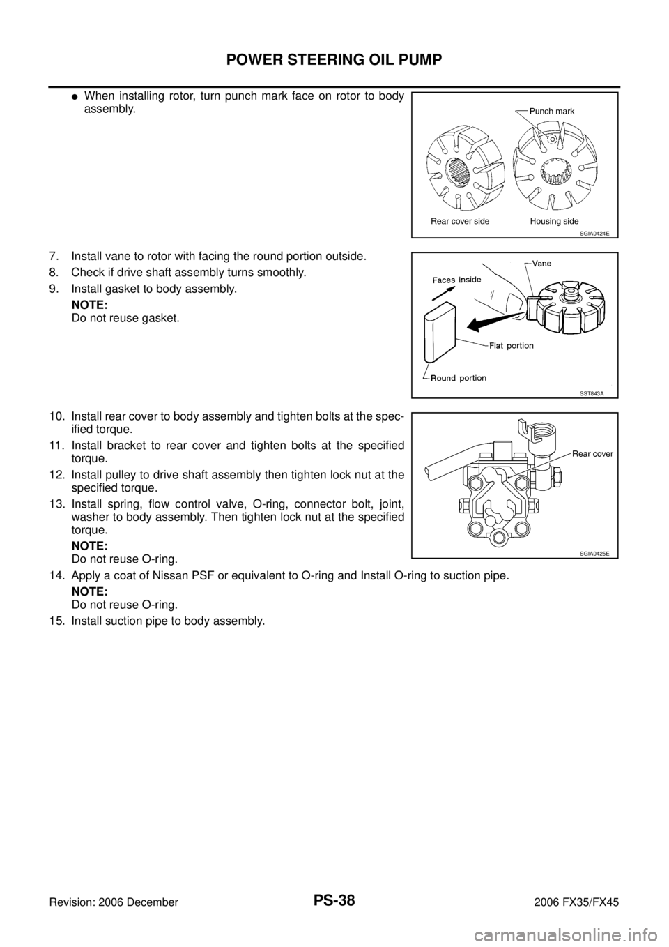
�When installing rotor, turn punch mark face on rotor to body
assembly.
7. Install vane to rotor with facing the round portion outside.
8. Check if drive shaft assembly turns smoothly.
9. Install gasket to body assembly. NOTE:
Do not reuse gasket.
10. Install rear cover to body assembly and tighten bolts at the spec- ified torque.
11. Install bracket to rear cover and tighten bolts at the specified torque.
12. Install pulley to drive shaft assembly then tighten lock nut at the specified torque.
13. Install spring, flow control valve, O-ring, connector bolt, joint, washer to body assembly. Then tighten lock nut at the specified
torque.
NOTE:
Do not reuse O-ring.
14. Apply a coat of Nissan PSF or equivalent to O-ring and Install O-ring to suction pipe. NOTE:
Do not reuse O-ring.
15. Install suction pipe to body assembly.
SGIA0424E
SST843A
SGIA0425E
Page 3987 of 4462
HYDRAULIC LINE PS-39
C
D E
F
H I
J
K L
M A
B
PS
Revision: 2006 December 2006 FX35/FX45
HYDRAULIC LINEPFP:49721
ComponentsNGS000CA
VQ35DE 2WD MODEL
SGIA0559E
1. Reservoir tank 2. Reservoir tank bracket 3. Suction hose
4. High pressure hose 5. Oil pump 6. Steering gear assembly
Page 3988 of 4462
PS-40
HYDRAULIC LINE
Revision: 2006 December 2006 FX35/FX45
VQ35DE AWD MODEL
7. Oil cooler 8. Eye bolt 9. Copper washer
10. Oil pressure sensor
SGIA0560E
1. Reservoir tank 2. Reservoir tank bracket 3. Suction hose
4. High pressure hose 5. Oil pump 6. Steering gear assembly
7. Oil cooler 8. Eye bolt 9. Copper washer
10. Oil pressure sensor
Page 3990 of 4462
PS-42
HYDRAULIC LINE
Revision: 2006 December 2006 FX35/FX45
ComponentNGS000CC
VK45DE AWD MODEL
SGIA0727E
1. Reservoir tank 2. Suction hose 3. High pressure hose
4. Oil cooler 5. Steering gear assembly 6. Reservoir tank bracket
7. Eye bolt
Page 3993 of 4462
SERVICE DATA AND SPECIFICATIONS (SDS) PS-45
C
D E
F
H I
J
K L
M A
B
PS
Revision: 2006 December 2006 FX35/FX45
Steering GearNGS000CI
Oil PumpNGS000CJ
Steering FluidNGS000CK
Tie-rod length “L” 135.2 mm (5.32 in)
SGIA0167E
Steering gear model PR26AM
Rack neutral position, dimension “L” (rack stroke) 67.0 mm (2.64 in)
Rack sliding force At the neutral point:
Range within ± 11.5 mm
( ± 0.453 in) from the neutral
position
(in power ON) Area average value 147
− 211 N (15 − 21.5 kg, 33 − 47 lb)
Allowable variation 98 N (10 kg, 22 lb) or less
Whole area (in power OFF) Peak value 294 N (30 kg, 66 lb) or less
Allowable variation 147 N (15 kg, 33 lb) or less
SGIA0629J
Oil pump relief hydraulic pressure 9,900 − 10,700 kPa (101 − 109.1 kg/cm2 , 1436 − 1552 psi)
Fluid capacity
Approx. 1.0 (1-1/8 US qt, 7/8 Imp qt)
Page 4000 of 4462

RAX-6
REAR WHEEL HUB AND KNUCKLE
Revision: 2006 December 2006 FX35/FX45
9. Remove parking brake cable and parking brake shoe from back plate. Refer to PB-6, "PARKING BRAKE
SHOE" and PB-4, "PARKING BRAKE CONTROL" .
10. Remove fixing nuts of anchor block with power tool, then remove anchor block and back plate from axle.
11. Loosen fixing bolts and nuts of front lower link, radius rod, and rear lower link in side of suspension mem- ber.
12. Set jack under rear lower link. Then remove fixing bolt in front lower link side of shock absorber with power tool.
13. Remove bolt and nut in axle side of rear lower link with power tool. Then remove coil spring. Refer to RSU-15, "
REAR LOWER LINK & COIL SPRING" .
14. Remove fixing bolts and nuts in axle side of front lower link, radius rod with power tool.
15. Remove suspension arm and cotter pin at axle, then loosen mounting nut.
16. Use a ball joint remover (suitable tool) to remove suspension arm from axle. Be careful not to damage ball joint boot.
CAUTION:
Tighten temporarily mounting nut to prevent damage to threads and to prevent ball joint remover
(suitable tool) from coming off.
17. Remove axle from vehicle.
INSPECTION AFTER REMOVAL
Check for deformity, cracks and damage on each parts, replace if necessary.
Ball Joint Inspection
Check for boot breakage, axial looseness, and torque of suspension arm ball joint. Refer to RSU-11,
"INSPECTION AFTER REMOVAL" .
INSTALLATION
�Refer to RAX-5, "Removal and Installation" for tightening torque. Install in the reverse order of removal.
NOTE:
Refer to component parts location and do not reuse non-reusable parts.
�Perform final tightening of installation position of suspension links (rubber bushing) under unladen condi-
tions with tires on level ground, Check wheel alignment. Refer to RSU-5, "
Wheel Alignment Inspection" .
�After adjusting wheel alignment, adjust neutral position of steering angle sensor. Refer to BRC-6, "Adjust-
ment of Steering Angle Sensor Neutral Position" .
Page 4012 of 4462
 “AIR BAG” and “SEAT
BELT PRE-TENSIONER”
NIS001SQ
The Suppleme")
RF-2
PRECAUTIONS
Revision: 2006 December 2006 FX35/FX45
PRECAUTIONSPFP:00001
Precautions for Supplemental Restraint System (SRS) “AIR BAG” and “SEAT
BELT PRE-TENSIONER”
NIS001SQ
The Supplemental Restraint System such as “AIR BAG” and “SEAT BELT PRE-TENSIONER”, used along
with a front seat belt, helps to reduce the risk or severity of injury to the driver and front passenger for certain
types of collision. This system includes seat belt switch inputs and dual stage front air bag modules. The SRS
system uses the seat belt switches to determine the front air bag deployment, and may only deploy one front
air bag, depending on the severity of a collision and whether the front occupants are belted or unbelted.
Information necessary to service the system safely is included in the SRS and SB section of this Service Man-
ual.
WARNING:
�To avoid rendering the SRS inoperative, which could increase the risk of personal injury or death
in the event of a collision which would result in air bag inflation, all maintenance must be per-
formed by an authorized NISSAN/INFINITI dealer.
�Improper maintenance, including incorrect removal and installation of the SRS, can lead to per-
sonal injury caused by unintentional activation of the system. For removal of Spiral Cable and Air
Bag Module, see the SRS section.
�Do not use electrical test equipment on any circuit related to the SRS unless instructed to in this
Service Manual. SRS wiring harnesses can be identified by yellow and/or orange harnesses or
harness connectors.
Precautions NIS001SR
�Disconnect both battery cables in advance.
�Do not tamper with or force air bag lid open, as this may adversely affect air bag performance.
�Be careful not to scratch pad and other parts.
�When removing or disassembling any part, be careful not to damage or deform it. Protect parts, which
may get in the way with cloth.
�When removing parts with a screwdriver or other tool, protect parts by wrapping them with vinyl or tape.
�Keep removed parts protected with cloth.
�If a clip is deformed or damaged, replace it.
�If an unreusable part is removed, replace it with a new one.
�Tighten bolts and nuts firmly to the specified torque.
�After re-assembly has been completed, make sure each part functions correctly.
�Remove stains in the following way.
Water-soluble stains:
Dip a soft cloth in warm water, and then squeeze it tightly. After wiping the stain, wipe with a soft dry cloth.
Oil stain:
Dissolve a synthetic detergent in warm water (density of 2 to 3% or less), dip the cloth, then clean off the stain
with the cloth. Next, dip the cloth in fresh water and squeeze it tightly. Then clean off the detergent completely.
Then wipe the area with a soft dry cloth.
�Do not use any organic solvent, such as thinner or benzine.
Page 4039 of 4462

RFD-1
REAR FINAL DRIVE
D DRIVELINE/AXLE
CONTENTS
C E F
G H
I
J
K L
M
SECTION RFD
A
B
RFD
Revision: 2006 December 2006 FX35/FX45
REAR FINAL DRIVE
PRECAUTIONS ..................................................... ..... 2
Service Notice or Precautions ............................. ..... 2
PREPARATION ...................................................... ..... 3
Special Service Tools .......................................... ..... 3
Commercial Service Tools ................................... ..... 6
NOISE, VIBRATION AND HARSHNESS (NVH)
TROUBLESHOOTING ........................................... ..... 7
NVH Troubleshooting Chart ................................ ..... 7
DESCRIPTION ....................................................... ..... 8
Cross-Sectional View .......................................... ..... 8
DIFFERENTIAL GEAR OIL ................................... ..... 9
Changing Differential Gear Oil ............................ ..... 9
DRAINING ........................................................ ..... 9
FILLING ............................................................ ..... 9
Checking Differential Gear Oil ............................. ..... 9
OIL LEAKAGE AND OIL LEVEL ...................... ..... 9
FRONT OIL SEAL ................................................. ... 10
Removal and Installation ..................................... ... 10
IDENTIFICATION STAMP OF REPLACEMENT
FREQUENCY OF FRONT OIL SEAL .............. ... 10
REMOVAL ........................................................ ... 10
INSTALLATION ................................................ ... 12
SIDE OIL SEAL ..................................................... ... 14
Removal and Installation ..................................... ... 14
REMOVAL ........................................................ ... 14
INSTALLATION ................................................ ... 14 REAR FINAL DRIVE ASSEMBLY .........................
... 16
Removal and Installation ..................................... ... 16
COMPONENTS ................................................ ... 16
REMOVAL ........................................................ ... 16
INSTALLATION ................................................ ... 17
Disassembly and Assembly ................................. ... 18
COMPONENTS ................................................ ... 18
ASSEMBLY INSPECTION AND ADJUSTMENT ... 19
DISASSEMBLY ................................................ ... 22
INSPECTION AFTER DISASSEMBLY ............. ... 26
ADJUSTMENT AND SELECTION OF ADJUST-
ING WASHERS ................................................ ... 26
ASSEMBLY ...................................................... ... 31
SERVICE DATA AND SPECIFICATIONS (SDS) ... ... 37
General Specifications ......................................... ... 37
Inspection and Adjustment .................................. ... 37
DRIVE GEAR RUNOUT ................................... ... 37
DIFFERENTIAL SIDE GEAR CLEARANCE .... ... 37
PRELOAD TORQUE ........................................ ... 37
BACKLASH ...................................................... ... 37
COMPANION FLANGE RUNOUT .................... ... 37
SELECTIVE PARTS ......................................... ... 37


 PS-45
C
D E
F
H I
J
K L
M A
B
PS
Revision: 2006 December 2006 FX35/FX45
Steering GearNGS000CI
Oil PumpNGS000CJ
Steering FluidNGS000CK
Tie-rod length �")