Page 3642 of 4462
LT-80
FRONT FOG LAMP
Revision: 2006 December 2006 FX35/FX45
Wiring Diagram — F/FOG —NKS002X0
TKWM4303E
Page 3645 of 4462

FRONT FOG LAMP LT-83
C
D E
F
G H
I
J
L
M A
B
LT
Revision: 2006 December 2006 FX35/FX45
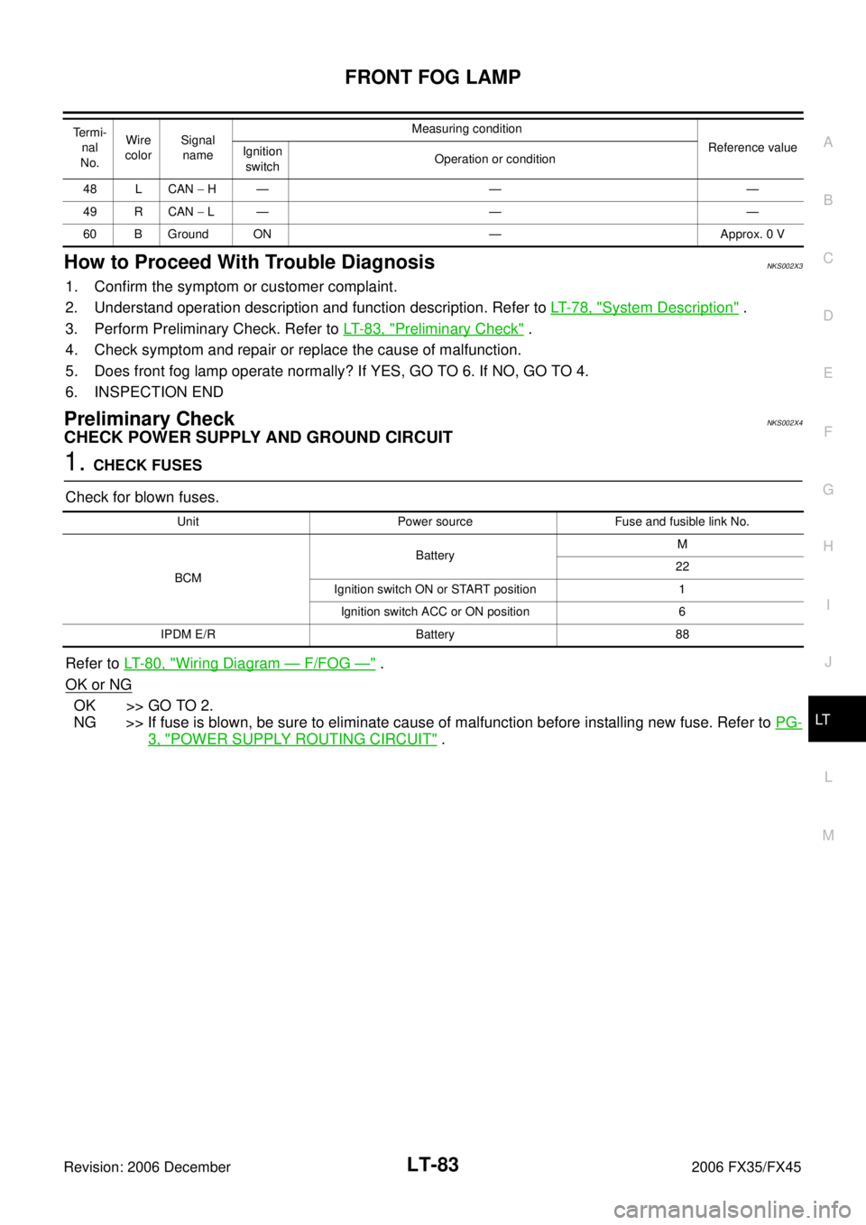
How to Proceed With Trouble DiagnosisNKS002X3
1. Confirm the symptom or customer complaint.
2. Understand operation description and function description. Refer to LT- 7 8 , "
System Description" .
3. Perform Preliminary Check. Refer to LT- 8 3 , "
Preliminary Check" .
4. Check symptom and repair or replace the cause of malfunction.
5. Does front fog lamp operate normally? If YES, GO TO 6. If NO, GO TO 4.
6. INSPECTION END
Preliminary CheckNKS002X4
CHECK POWER SUPPLY AND GROUND CIRCUIT
1. CHECK FUSES
Check for blown fuses.
Refer to LT- 8 0 , "
Wiring Diagram — F/FOG —" .
OK or NG
OK >> GO TO 2.
NG >> If fuse is blown, be sure to eliminate cause of malfunction before installing new fuse. Refer to PG-
3, "POWER SUPPLY ROUTING CIRCUIT" .
48 L CAN − H— — —
49 R CAN − L— — —
60 B Ground ON — Approx. 0 V
Termi-
nal
No. Wire
color Signal
name Measuring condition
Reference value
Ignition
switch Operation or condition
Unit Power source Fuse and fusible link No.
BCM Battery
M
22
Ignition switch ON or START position 1 Ignition switch ACC or ON position 6
IPDM E/R Battery 88
Page 3657 of 4462
TURN SIGNAL AND HAZARD WARNING LAMPS LT-95
C
D E
F
G H
I
J
L
M A
B
LT
Revision: 2006 December 2006 FX35/FX45
Wiring Diagram — TURN —NKS002XH
TKWM4306E
Page 3664 of 4462

LT-102
TURN SIGNAL AND HAZARD WARNING LAMPS
Revision: 2006 December 2006 FX35/FX45
How to Proceed With Trouble DiagnosisNKS002XJ
1. Confirm the symptom or customer complaint.
2. Understand operation description and function description. Refer to LT- 9 0 , "
System Description" .
3. Perform preliminary check. Refer to LT- 1 0 2 , "
Preliminary Check" .
4. Check symptom and repair or replace the cause of malfunction.
5. Do turn signal and hazard warning lamps operate normally? If YES, GO TO 6. If NO, GO TO 4.
6. INSPECTION END
Preliminary CheckNKS002XK
CHECK POWER SUPPLY AND GROUND CIRCUIT
1. CHECK FUSES
Check for blown fuses.
Refer to LT- 9 5 , "
Wiring Diagram — TURN —" .
OK or NG
OK >> GO TO 2.
NG >> If fuse is blown, be sure to eliminate cause of malfunction before installing new fuse. Refer to PG-
3, "POWER SUPPLY ROUTING CIRCUIT" .
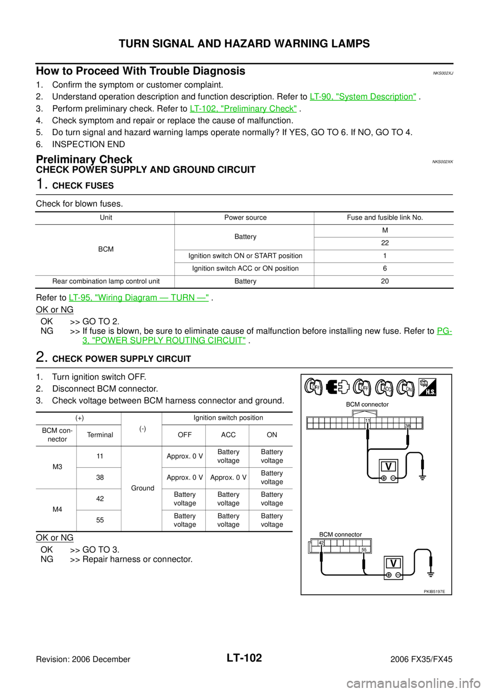
2. CHECK POWER SUPPLY CIRCUIT
1. Turn ignition switch OFF.
2. Disconnect BCM connector.
3. Check voltage between BCM harness connector and ground.
OK or NG
OK >> GO TO 3.
NG >> Repair harness or connector.
Unit Power source Fuse and fusible link No.
BCM Battery
M
22
Ignition switch ON or START position 1 Ignition switch ACC or ON position 6
Rear combination lamp control unit Battery 20
(+) (-) Ignition switch position
OFF ACC ON
BCM con-
nector Terminal
M3 11
Ground Approx. 0 V
Battery
voltage Battery
voltage
38 Approx. 0 V Approx. 0 V Battery
voltage
M4 42
Battery
voltage Battery
voltage Battery
voltage
55 Battery
voltage Battery
voltage Battery
voltage
PKIB5197E
Page 3675 of 4462
COMBINATION SWITCH LT-113
C
D E
F
G H
I
J
L
M A
B
LT
Revision: 2006 December 2006 FX35/FX45
COMBINATION SWITCHPFP:25567
Wiring Diagram — COMBSW —NKS002XX
TKWM4309E
Page 3687 of 4462
STOP LAMP LT-125
C
D E
F
G H
I
J
L
M A
B
LT
Revision: 2006 December 2006 FX35/FX45
Wiring Diagram — STOP/L —NKS002Y5
TKWM4310E
Page 3693 of 4462
BACK-UP LAMP LT-131
C
D E
F
G H
I
J
L
M A
B
LT
Revision: 2006 December 2006 FX35/FX45
BACK-UP LAMPPFP:26550
Wiring Diagram — BACK/L —NKS003GW
TKWM4313E
Page 3699 of 4462
PARKING, LICENSE PLATE AND TAIL LAMPS LT-137
C
D E
F
G H
I
J
L
M A
B
LT
Revision: 2006 December 2006 FX35/FX45
Wiring Diagram — TAIL/L —NKS003H4
TKWM4322E