2006 INFINITI FX35 diagram
[x] Cancel search: diagramPage 3706 of 4462
LT-144
PARKING, LICENSE PLATE AND TAIL LAMPS
Revision: 2006 December 2006 FX35/FX45
Terminals and Reference Value for Rear Combination Lamp Control UnitNKS003NA
Refer to LT- 9 9 , "Terminals and Reference Value for Rear Combination Lamp Control Unit" .
How to Proceed With Trouble DiagnosisNKS003H7
1. Confirm the symptom or customer complaint.
2. Understand operation description and function description. Refer to LT- 1 3 3 , "
System Description" .
3. Perform Preliminary Check. Refer to LT- 1 4 4 , "
Preliminary Check" .
4. Check symptom and repair or replace the cause of malfunction.
5. Do parking, license plate, side marker and tail lamps operate normally? If YES, GO TO 6. If NO, GO TO 4.
6. INSPECTION END
Preliminary CheckNKS003H8
CHECK POWER SUPPLY AND GROUND CIRCUIT
1. CHECK FUSES
Check for blown fuses.
Refer to LT- 1 3 7 , "
Wiring Diagram — TAIL/L —" .
OK or NG
OK >> GO TO 2.
NG >> If fuse is blown, be sure to eliminate cause of malfunction before installing new fuse. Refer to PG-
3, "POWER SUPPLY ROUTING CIRCUIT" .
2. CHECK POWER SUPPLY CIRCUIT
1. Turn ignition switch OFF.
2. Disconnect BCM connector.
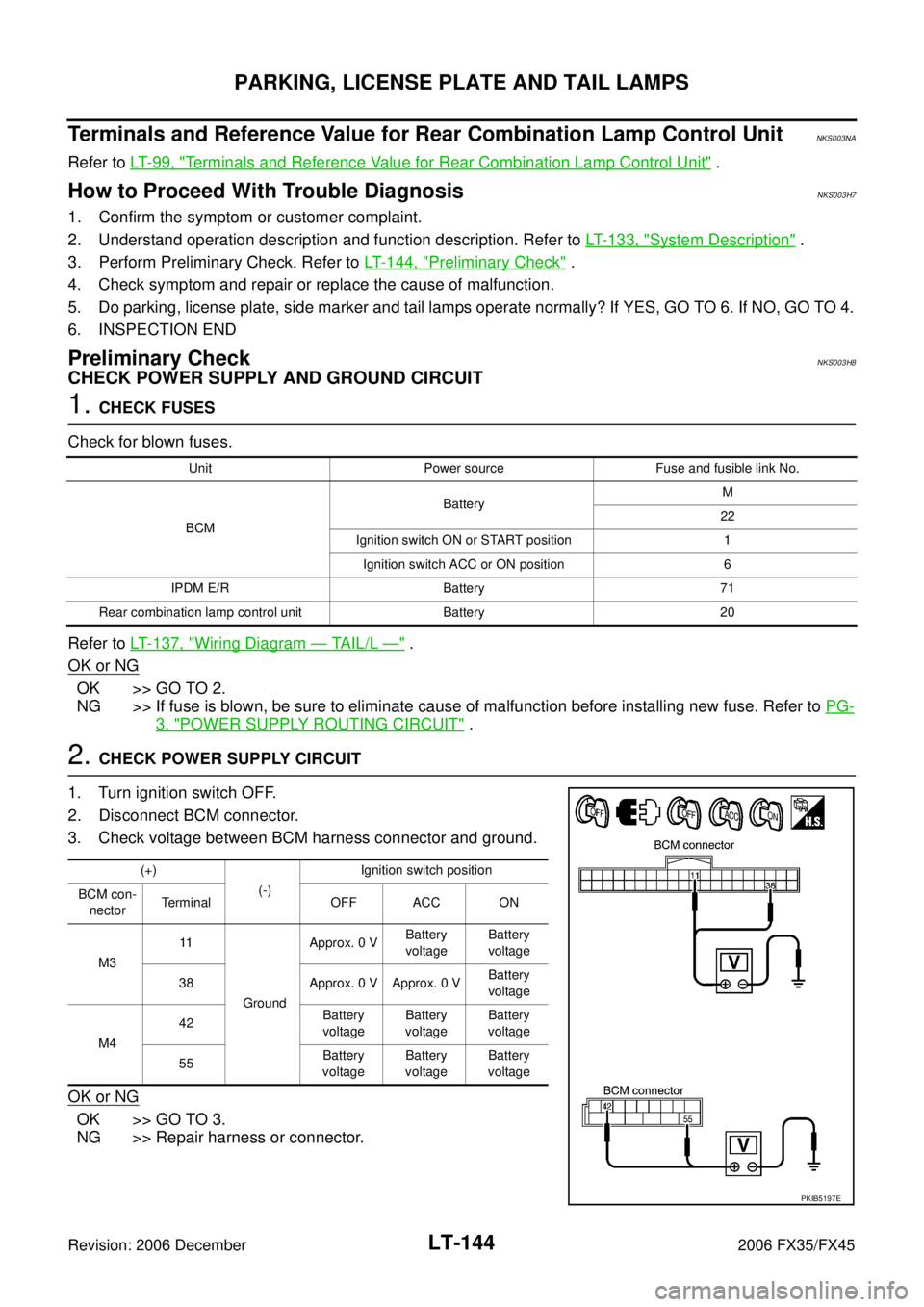
3. Check voltage between BCM harness connector and ground.
OK or NG
OK >> GO TO 3.
NG >> Repair harness or connector.
Unit Power source Fuse and fusible link No.
BCM Battery
M
22
Ignition switch ON or START position 1 Ignition switch ACC or ON position 6
IPDM E/R Battery 71
Rear combination lamp control unit Battery 20
(+) (-) Ignition switch position
BCM con- nector Terminal OFF ACC ON
M3 11
Ground Approx. 0 V
Battery
voltage Battery
voltage
38 Approx. 0 V Approx. 0 V Battery
voltage
M4 42
Battery
voltage Battery
voltage Battery
voltage
55 Battery
voltage Battery
voltage Battery
voltage
PKIB5197E
Page 3726 of 4462
LT-164
INTERIOR ROOM LAMP
Revision: 2006 December 2006 FX35/FX45
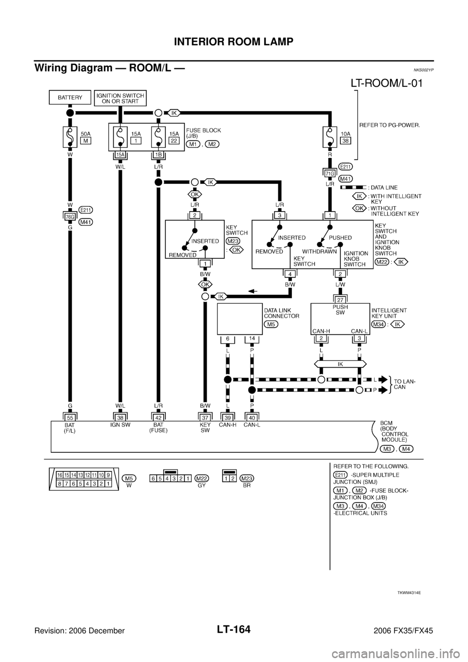
Wiring Diagram — ROOM/L —NKS002YP
TKWM4314E
Page 3735 of 4462
INTERIOR ROOM LAMP LT-173
C
D E
F
G H
I
J
L
M A
B
LT
Revision: 2006 December 2006 FX35/FX45
How to Proceed With Trouble DiagnosisNKS002YR
1. Confirm the symptom or customer complaint.
2. Understand operation description and function description. Refer to LT- 1 5 6 , "
System Description" .
3. Perform Preliminary Check. Refer to LT- 1 7 3 , "
Preliminary Check" .
4. Check symptom and repair or replace the cause of malfunction.
5. Does interior room lamp operate normally? If YES, GO TO 6. If NO, GO TO 4.
6. INSPECTION END
Preliminary CheckNKS002YS
CHECK FOR POWER SUPPLY AND GROUND CIRCUIT
1. CHECK FUSES
Check for blown fuses.
Refer to LT- 1 6 4 , "
Wiring Diagram — ROOM/L —" .
OK or NG
OK >> GO TO 2.
NG >> If fuse is blown, be sure to eliminate cause of malfunction before installing new fuse. Refer to PG-
3, "POWER SUPPLY ROUTING CIRCUIT" .
2. CHECK POWER SUPPLY CIRCUIT
1. Turn ignition switch OFF.
2. Disconnect BCM connector.
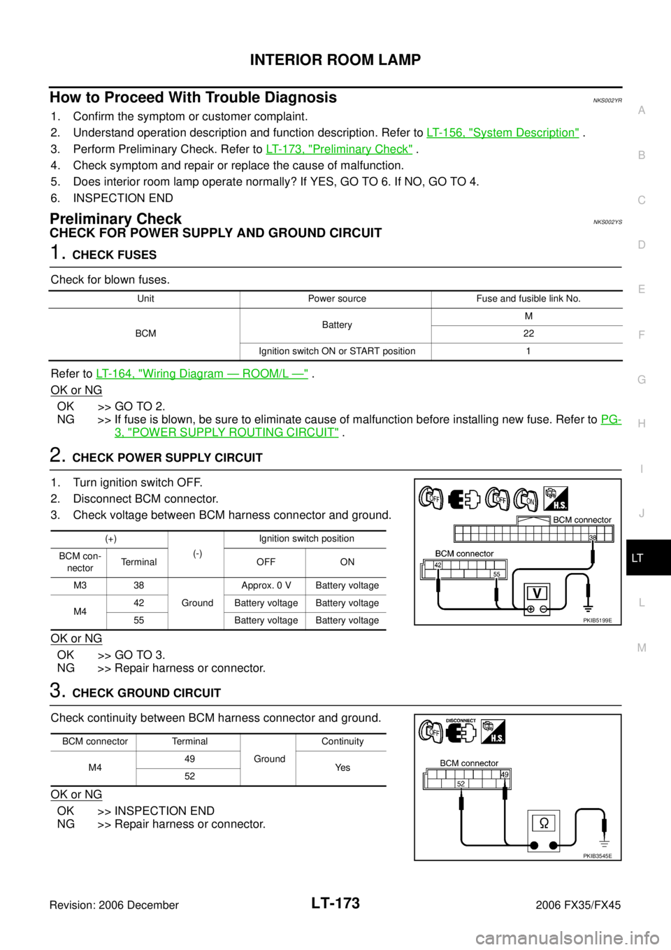
3. Check voltage between BCM harness connector and ground.
OK or NG
OK >> GO TO 3.
NG >> Repair harness or connector.
3. CHECK GROUND CIRCUIT
Check continuity between BCM harness connector and ground.
OK or NG
OK >> INSPECTION END
NG >> Repair harness or connector.
Unit Power source Fuse and fusible link No.
BCM Battery
M
22
Ignition switch ON or START position 1
(+) (-) Ignition switch position
BCM con- nector Terminal OFF ON
M3 38 Ground Approx. 0 V Battery voltage
M4 42 Battery voltage Battery voltage
55 Battery voltage Battery voltage
PKIB5199E
BCM connector Terminal Ground Continuity
M4 49
Ye s
52
PKIB3545E
Page 3756 of 4462
LT-194
ILLUMINATION
Revision: 2006 December 2006 FX35/FX45
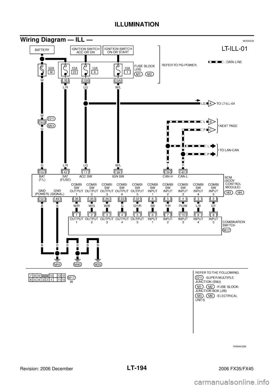
Wiring Diagram — ILL —NKS002Z6
TKWM4329E
Page 3853 of 4462

PG-1
POWER SUPPLY, GROUND & CIRCUIT ELEMENTS
K ELECTRICAL
CONTENTS
C
D E
F
G H
I
J
L
M
SECTION PG
A
B
PG
Revision: 2006 December 2006 FX35/FX45
POWER SUPPLY, GROUND & CIRCUIT ELEMENTS
POWER SUPPLY ROUTING CIRCUIT ................. ..... 3
Schematic ........................................................... ..... 3
Wiring Diagram — POWER — ............................ ..... 4
BATTERY POWER SUPPLY — IGNITION SW.
IN ANY POSITION ........................................... ..... 4
ACCESSORY POWER SUPPLY — IGNITION
SW. IN “ACC” OR “ON” .................................... ... 10
IGNITION POWER SUPPLY — IGNITION SW.
IN “ON” AND/OR “START” ............................... ... 12
Fuse .................................................................... ... 16
Fusible Link ......................................................... ... 16
Circuit Breaker .................................................... ... 16
IPDM E/R (INTELLIGENT POWER DISTRIBUTION
MODULE ENGINE ROOM) ................................... ... 17
System Description ............................................. ... 17
SYSTEMS CONTROLLED BY IPDM E/R ........ ... 17
CAN COMMUNICATION LINE CONTROL ...... ... 17
IPDM E/R STATUS CONTROL ........................ ... 18
CAN Communication System Description ........... ... 18
CAN Communication Unit ................................... ... 18
Function of Detecting Ignition Relay Malfunction ... 18
CONSULT-II Function (IPDM E/R) ...................... ... 19
CONSULT-II INSPECTION PROCEDURE ...... ... 19
SELF-DIAG RESULTS ..................................... ... 19
DATA MONITOR .............................................. ... 19
ACTIVE TEST .................................................. ... 20
Auto Active Test .................................................. ... 21
DESCRIPTION ................................................. ... 21
OPERATION PROCEDURE ............................ ... 21
INSPECTION IN AUTO ACTIVE TEST MODE ... 22
Schematic ........................................................... ... 24
IPDM E/R Terminal Arrangement ........................ ... 25
IPDM E/R Power/Ground Circuit Inspection ....... ... 26
Inspection With CONSULT-II (Self-Diagnosis) .... ... 27
Removal and Installation of IPDM E/R ................ ... 28
REMOVAL ........................................................ ... 28
INSTALLATION ................................................ ... 28 GROUND ................................................................
... 29
Ground Distribution .............................................. ... 29
MAIN HARNESS .............................................. ... 29
ENGINE ROOM HARNESS ............................. ... 32
ENGINE HARNESS/VK ENGINE MODELS ..... ... 35
ENGINE HARNESS/VQ ENGINE MODELS .... ... 36
ENGINE CONTROL HARNESS/VK ENGINE
MODELS .......................................................... ... 37
ENGINE CONTROL HARNESS/VQ ENGINE
MODELS .......................................................... ... 38
BODY HARNESS ............................................. ... 39
BODY NO. 2 HARNESS .................................. ... 42
ROOM LAMP HARNESS ................................. ... 43
HARNESS .............................................................. ... 44
Harness Layout ................................................... ... 44
HOW TO READ HARNESS LAYOUT .............. ... 44
OUTLINE .......................................................... ... 45
MAIN HARNESS .............................................. ... 46
ENGINE ROOM HARNESS ............................. ... 49
ENGINE HARNESS/VK ENGINE MODELS ..... ... 52
ENGINE HARNESS/VQ ENGINE MODELS .... ... 53
ENGINE CONTROL HARNESS/VK ENGINE
MODELS .......................................................... ... 54
ENGINE CONTROL HARNESS/VQ ENGINE
MODELS .......................................................... ... 56
BODY HARNESS ............................................. ... 58
BODY NO. 2 HARNESS .................................. ... 60
ROOM LAMP HARNESS ................................. ... 61
FRONT DOOR HARNESS ............................... ... 62
REAR DOOR HARNESS ................................. ... 63
BACK DOOR HARNESS ................................. ... 64
Wiring Diagram Codes (Cell Codes) ................... ... 65
ELECTRICAL UNITS LOCATION ......................... ... 68
Electrical Units Location ...................................... ... 68
ENGINE COMPARTMENT ............................... ... 68
PASSENGER COMPARTMENT ...................... ... 69
LUGGAGE COMPARTMENT ........................... ... 71
HARNESS CONNECTOR ...................................... ... 72
Description ........................................................... ... 72
HARNESS CONNECTOR (TAB-LOCKING
Page 3856 of 4462
PG-4
POWER SUPPLY ROUTING CIRCUIT
Revision: 2006 December 2006 FX35/FX45
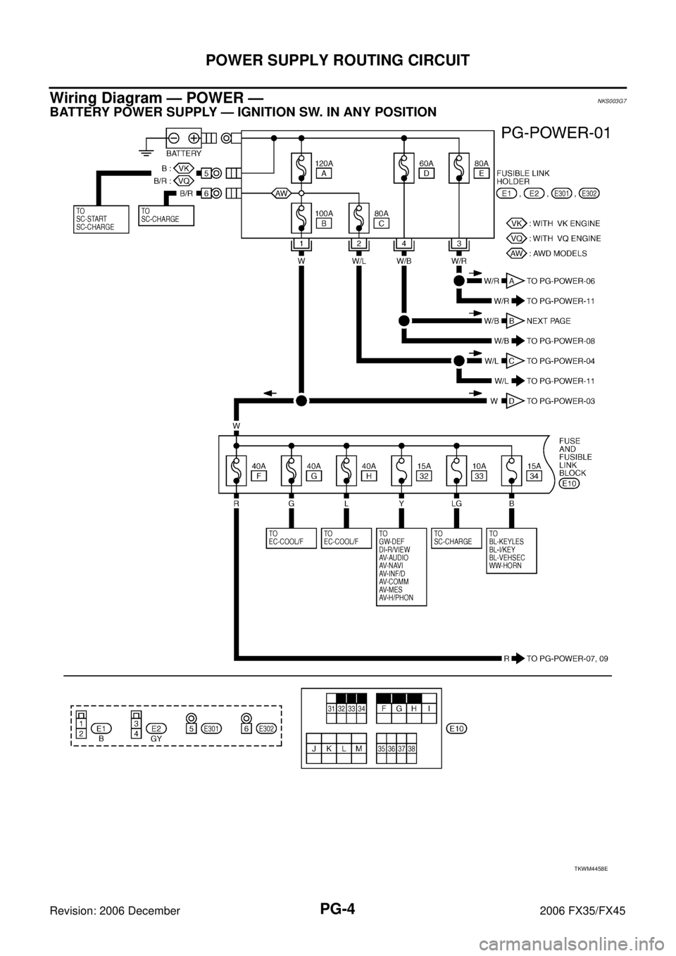
Wiring Diagram — POWER —NKS003G7
BATTERY POWER SUPPLY — IGNITION SW. IN ANY POSITION
TKWM4458E
Page 3917 of 4462

HARNESS PG-65
C
D E
F
G H
I
J
L
M A
B
PG
Revision: 2006 December 2006 FX35/FX45
Wiring Diagram Codes (Cell Codes) NKS003GO
Use the chart below to find out what each wiring diagram code stands for.
Refer to the wiring diagram code in the alphabetical index to find the location (page number) of each wiring
diagram.
Code Section Wiring Diagram Name
A/C ATC Air Conditioner
AF1B1 EC Air Fuel Ratio Sensor 1 Bank 1
AF1B2 EC Air Fuel Ratio Sensor 1 Bank 2
AF1HB1 EC Air Fuel Ratio Sensor 1 Heater Bank 1
AF1HB2 EC Air Fuel Ratio Sensor 1 Heater Bank 2
APPS1 EC Accelerator Pedal Position Sensor
APPS2 EC Accelerator Pedal Position Sensor
APPS3 EC Accelerator Pedal Position Sensor
ASC/BS EC Automatic Speed Control Device (ASCD) Brake Switch
ASC/SW EC Automatic Speed Control Device (ASCD) Steering Switch
ASCBOF EC Automatic Speed Control Device (ASCD) Brake Switch
ASCIND EC Automatic Speed Control Device (ASCD) Indicator
AT/IND DI A/T Indicator Lamp
AUDIO AV Audio
AUT/DP SE Automatic Drive Positioner
AUTO/L LT Automatic Light System
AWD TF AWD Control System
B/CLOS BL Back Door Closure System
BACK/L LT Back-Up Lamp
BRK/SW EC Brake Switch
CAN AT CAN Communication Line
CAN EC CAN Communication Line
CAN LAN CAN System
CHARGE SC Charging System
CHIME DI Warning Chime
CLOCK DI Clock
COMBSW LT Combination Switch
COMM AV Audio Visual Communication Line
COMPAS DI Compass
COOL/F EC Cooling Fan Control
D/LOCK BL Power Door Lock
DEF GW Rear Window Defogger
DTRL LT Headlamp - With Daytime Light System
ECM/PW EC ECM Power Supply for Back-Up
ECTS EC Engine Coolant Temperature Sensor
ETC1 EC Electric Throttle Control Function
ETC2 EC Electric Throttle Control Motor Relay
ETC3 EC Electric Throttle Control Motor
F/FOG LT Front Fog Lamp
F/PUMP EC Fuel Pump
FTS AT A/T Fluid Temperature Sensor Circuit
Page 3918 of 4462

PG-66
HARNESS
Revision: 2006 December 2006 FX35/FX45
FTTS EC Fuel Tank Temperature Sensor
FUELB1 EC Fuel Injection System Function (Bank 1)
FUELB2 EC Fuel Injection System Function (Bank 2)
H/AIM LT Headlamp Aiming Control System
H/LAMP LT Headlamp
H/PHON AV Hands Free Telephone
HORN WW Horn
HSEAT SE Heated Seat
I/KEY BL Intelligent Key System
I/MIRR GW Inside Mirror (Auto Anti-Dazzling Mirror)
IATS EC Intake Air Temperature Sensor
ICC ACS Intelligent Cruise Control System
ICC/BS EC ICC Brake Switch
ICC/SW EC ICC Steering Switch
ICCBOF EC ICC Brake Switch
IGNSYS EC Ignition System
ILL LT Illumination
INF/D AV Vehicle Information and Integrated Switch System
INJECT EC Injector
IVCB1 EC Intake Valve Timing Control Solenoid Valve Bank 1
IVCB2 EC Intake Valve Timing Control Solenoid Valve Bank 2
IVCSB1 EC Intake Valve Timing Control Position Sensor Bank 1
IVCSB2 EC Intake Valve Timing Control Position Sensor Bank 2
IVTB1 EC Intake Valve Timing Control System (Bank 1)
IVTB2 EC Intake Valve Timing Control System (Bank 2)
KEYLES BL Remote Keyless Entry System
KS EC Knock Sensor
LDW DI Lane Departure Warning System
M/ANT AV Manual Antenna
MAFS EC Mass Air Flow Sensor
MAIN AT Main Power Supply and Ground Circuit
MAIN EC Main Power Supply and Ground Circuit
MES AV Mobile Entertainment System
METER DI Speedometer, Tachometer, Temp. and Fuel Gauges
MIL/DL EC MIL & Data Link Connectors
MIRROR GW Power Door Mirror
MMSW AT Manual Mode Switch
NATS BL Nissan Anti-Theft System
NAVI AV Navigation System
NONDTC AT Non-Detective Items
O2H2B1 EC Heated Oxygen Sensor 2 Heater Bank 1
O2H2B2 EC Heated Oxygen Sensor 2 Heater Bank 2
O2S2B1 EC Heated Oxygen Sensor 2 Bank 1
O2S2B2 EC Heated Oxygen Sensor 2 Bank 2 Code Section Wiring Diagram Name