Page 346 of 4462

AT-262
ON-VEHICLE SERVICE
Revision: 2006 December 2006 FX35/FX45
INSTALLATION
CAUTION:
After completing installation, check A/T position, A/T fluid leakage and A/F fluid level. Refer to AT- 2 3 1 ,
"Checking of A/T Position" , AT- 1 3 , "Checking A/T Fluid" .
1. Install revolution sensor in transmission case, and then tighten revolution sensor mounting bolt to the specified torque. Refer to
AT- 2 5 9 , "
COMPONENTS" .
CAUTION:
�Do not subject it to impact by dropping or hitting it.
�Do not disassemble.
�Do not allow metal filings, etc. to get on the sensor's front
edge magnetic area.
�Do not place in an area affected by magnetism.
2. Connect revolution sensor connector.
3. Securely fasten revolution sensor harness with clip.
4. Apply recommended sealant (Genuine Anaerobic Liquid Gasket or equivalent. Refer to GI-48, "
Recommended Chemical Prod-
ucts and Sealants" .) to rear extension assembly as shown in
the figure.
CAUTION:
Completely remove all moisture, oil and old sealant, etc.
from transmission case and rear extension assembly
mounting surfaces.
SCIA3997E
SCIA7524E
SCIA7525E
SCIA5212E
Page 384 of 4462
AT-300
DISASSEMBLY
Revision: 2006 December 2006 FX35/FX45
28. Remove oil pan and oil pan gasket.
29. Check foreign materials in oil pan to help determine causes of malfunction. If the A/T fluid is very dark, smells burned, or con-
tains foreign particles, the frictional material (clutches, band)
may need replacement. A tacky film that will not wipe clean indi-
cates varnish build up. Varnish can cause valves, servo, and
clutches to stick and can inhibit pump pressure.
�If frictional material is detected, perform A/T fluid cooler
cleaning. Refer to AT- 1 5 , "
A/T Fluid Cooler Cleaning" .
30. Remove magnets from oil pan.
31. Disconnect A/T fluid temperature sensor 2 connector. CAUTION:
Be careful not to damage connector.
32. Straighten terminal clips to free terminal cord assembly and A/T fluid temperature sensor 2 harness.
SCIA2308E
SCIA5199E
SCIA5200E
SCIA5023E
SCIA5446E
Page 390 of 4462

AT-306
DISASSEMBLY
Revision: 2006 December 2006 FX35/FX45
49. Remove revolution sensor from transmission case. CAUTION:
�Do not subject it to impact by dropping or hitting it.
�Do not disassemble.
�Do not allow metal filings, etc. to get on the sensor's front
edge magnetic area.
�Do not place in an area affected by magnetism.
50. Remove reverse brake snap ring (fixing plate) using 2 flat- bladed screwdrivers.
NOTE:
Press out snap ring from the transmission case oil pan side gap
using a flat-bladed screwdriver, and remove it using another
screwdriver.
51. Remove reverse brake retaining plate from transmission case.
�Check facing for burns, cracks or damage. If necessary,
replace the plate.
52. Remove N-spring from transmission case.
53. Remove reverse brake drive plates, driven plates and dish plate from transmission case.
�Check facing for burns, cracks or damage. If necessary,
replace the plate.
54. Remove snap ring (fixing spring retainer) using a flat-bladed screwdriver.
SCIA2320E
SCIA5032E
SCIA5214E
SCIA2322E
SCIA2323E
Page 400 of 4462
AT-316
REPAIR FOR COMPONENT PARTS
Revision: 2006 December 2006 FX35/FX45
INSPECTION
3rd One-way Clutch
�Check frictional surface for wear or damage.
CAUTION:
If necessary, replace the 3rd one-way clutch.
Front Sun Gear Snap Ring
�Check for deformation, fatigue or damage.
CAUTION:
If necessary, replace the snap ring.
Front Sun Gear
�Check for deformation, fatigue or damage.
CAUTION:
If necessary, replace the front sun gear.
ASSEMBLY
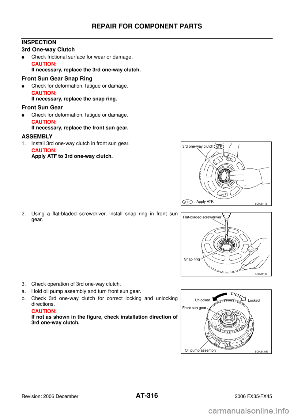
1. Install 3rd one-way clutch in front sun gear.
CAUTION:
Apply ATF to 3rd one-way clutch.
2. Using a flat-bladed screwdriver, install snap ring in front sun gear.
3. Check operation of 3rd one-way clutch.
a. Hold oil pump assembly and turn front sun gear.
b. Check 3rd one-way clutch for correct locking and unlocking directions.
CAUTION:
If not as shown in the figure, check installation direction of
3rd one-way clutch.
S C I A 3 111 E
SCIA3110E
SCIA3131E
Page 442 of 4462
AT-358
ASSEMBLY
Revision: 2006 December 2006 FX35/FX45
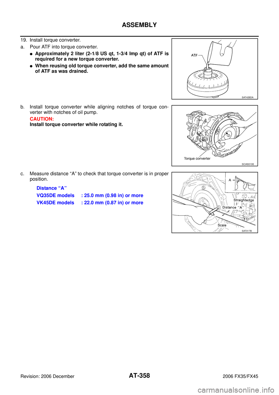
19. Install torque converter.
a. Pour ATF into torque converter.
�Approximately 2 liter (2-1/8 US qt, 1-3/4 Imp qt) of ATF is
required for a new torque converter.
�When reusing old torque converter, add the same amount
of ATF as was drained.
b. Install torque converter while aligning notches of torque con- verter with notches of oil pump.
CAUTION:
Install torque converter while rotating it.
c. Measure distance “A” to check that torque converter is in proper position.
SAT428DA
SCIA5010E
Distance “A”
VQ35DE models : 25.0 mm (0.98 in) or more
VK45DE models : 22.0 mm (0.87 in) or more
SAT017B
Page 465 of 4462

Refrigerant dye leak detection kit
Kit includes:
(J-42220)
UV lamp and UV safety goggles")
PREPARATION ATC-19
C
D E
F
G H
I
K L
M A
B
AT C
Revision: 2006 December 2006 FX35/FX45
(J-43926)
Refrigerant dye leak detection kit
Kit includes:
(J-42220)
UV lamp and UV safety goggles
(J-41459)
HFC-134a (R-134a) dye injector
Use with J-41447, 1/4 ounce
bottle
(J-41447)
HFC-134a (R-134a) fluorescent
leak detection dye
(Box of 24, 1/4 ounce bottles)
(J-43872)
Refrigerant dye cleaner Power supply:
DC 12 V (Battery terminal)
(J-42220)
UV lamp and UV safety goggles Power supply:
DC 12 V (Battery terminal)
For checking refrigerant leak when
fluorescent dye is installed in A/C
system
Includes:
UV lamp and UV safety goggles
(J-41447)
HFC-134a (R-134a) fluorescent
leak detection dye
(Box of 24, 1/4 ounce bottles) Application:
For HFC-134a (R-134a) PAG oil
Container:
1/4 ounce (7.4 cc) bottle
(Includes self-adhesive dye
identification labels for affixing to
vehicle after charging system with
dye.)
(J-41459)
HFC-134a (R-134a) dye injector
Use with J-41447, 1/4 ounce
bottle For injecting 1/4 ounce of fluorescent
leak detection dye into A/C system
(J-43872)
Refrigerant dye cleaner For cleaning dye spills
(J-39183)
Manifold gauge set (with hoses
and couplers) Identification:
�The gauge face indicates HFC-134a
(R-134a).
Fitting size: Thread size
�1/2″ -16 ACME
Tool number
(Kent-Moore No.)
Tool name Description
ZHA200H
SHA438F
SHA439F
SHA440F
SHA441F
RJIA0196E
Page 466 of 4462

�Low-pressure side hose
(J-39502-72)
�Utility hose
(J-")
ATC-20
PREPARATION
Revision: 2006 December 2006 FX35/FX45
Commercial Service ToolsNJS000DG
Service hoses
�High-pressure side hose
(J-39501-72)
�Low-pressure side hose
(J-39502-72)
�Utility hose
(J-39476-72) Hose color:
�Low hose: Blue with black stripe
�High hose: Red with black stripe
�Utility hose: Yellow with black stripe
or green with black stripe
Hose fitting to gauge:
�1/2″ -16 ACME
Service couplers
�High-pressure side coupler
(J-39500-20)
�Low-pressure side coupler
(J-39500-24) Hose fitting to service hose:
M14 x 1.5 fitting is optional or
permanently attached.
(J-39650)
Refrigerant weight scale For measuring of refrigerant
Fitting size: Thread size
1/2
″ -16 ACME
(J-39649)
Vacuum pump
(Including the isolator valve) Capacity:
�Air displacement: 4 CFM
�Micron rating: 20 microns
�Oil capacity: 482 g (17 oz.)
Fitting size: Thread size
�1/2″ -16 ACME
Tool number
(Kent-Moore No.)
Tool name Description
S-NT201
S-NT202
S-NT200
S-NT203
Tool name
Description
Refrigerant identifier equipment Checking for refrigerant purity and
system contamination
Power tool For loosening bolts and nuts
RJIA0197E
PBIC0190E
Page 473 of 4462

LUBRICANT ATC-27
C
D E
F
G H
I
K L
M A
B
AT C
Revision: 2006 December 2006 FX35/FX45
LUBRICANTPFP:KLG00
Maintenance of Lubricant Quantity in CompressorNJS000DL
The lubricant in the compressor circulates through the system with the refrigerant. Add lubricant to compres-
sor when replacing any component or after a large refrigerant leakage occurred. It is important to maintain the
specified amount.
If lubricant quantity is not maintained properly, the following malfunctions may result:
�Lack of lubricant: May lead to a seized compressor.
�Excessive lubricant: Inadequate cooling (thermal exchange interference)
LUBRICANT
LUBRICANT RETURN OPERATION
Adjust the lubricant quantity according to the test group shown below.
1. CHECK LUBRICANT RETURN OPERATION
Can lubricant return operation be performed?
�A/C system works properly.
�There is no evidence of a large amount of lubricant leakage.
CAUTION:
If excessive lubricant leakage is noted, never perform the lubricant return operation.
OK or NG
OK >> GO TO 2.
NG >> GO TO 3.
2. PERFORM LUBRICANT RETURN OPERATION, PROCEEDING AS FOLLOWS
1. Start the engine, and set to the following conditions:
–Engine speed: Idling to 1,200 rpm
–A/C switch: ON
–Blower speed: Max. position
–Temp. control: Optional [Set so that intake air temperature is 25 to 30 °C (77 to 86 °F).]
–Intake position: Recirculation (REC)
2. Perform lubricant return operation for about 10 minutes.
3. Stop the engine.
>> GO TO 3.
3. CHECK REPLACEMENT PART
Should the compressor be replaced?
YES >> GO TO AT C - 2 9 , "LUBRICANT ADJUSTING PROCEDURE FOR COMPRESSOR REPLACE-
MENT" .
NO >> GO TO AT C - 2 8 , "
LUBRICANT ADJUSTING PROCEDURE FOR COMPONENTS REPLACE-
MENT EXCEPT COMPRESSOR" .
Name : NISSAN A/C System Oil Type S