Page 2960 of 4462
EM-166
[VK45DE]
PRECAUTIONS
Revision: 2006 December 2006 FX35/FX45
3. Attach liquid gasket tube to tube presser [SST: WS39930000 (—)].
Use Genuine RTV Silicone Sealant or equivalent. Refer to
GI-48, "
RECOMMENDED CHEMICAL PRODUCTS AND
SEALANTS" .
4. Apply liquid gasket without breaks to the specified location with the specified dimensions.
�If there is a groove for the liquid gasket application, apply liquid gasket to the groove.
�As for the bolt holes, normally apply liquid gasket inside the
holes. Occasionally, it should be applied outside the holes.
Make sure to read the text of this manual.
�Within five minutes of liquid gasket application, install the mat-
ing component.
�If liquid gasket protrudes, wipe it off immediately.
�Do not retighten after the installation.
�Wait 30 minutes or more after installation before refilling
engine with engine oil and engine coolant.
CAUTION:
If there are specific instructions in this manual, observe
them.
EMA0622D
SEM159F
Page 2967 of 4462
ENGINE ROOM COVER EM-173
[VK45DE]
C
D E
F
G H
I
J
K L
M A
EM
Revision: 2006 December 2006 FX35/FX45
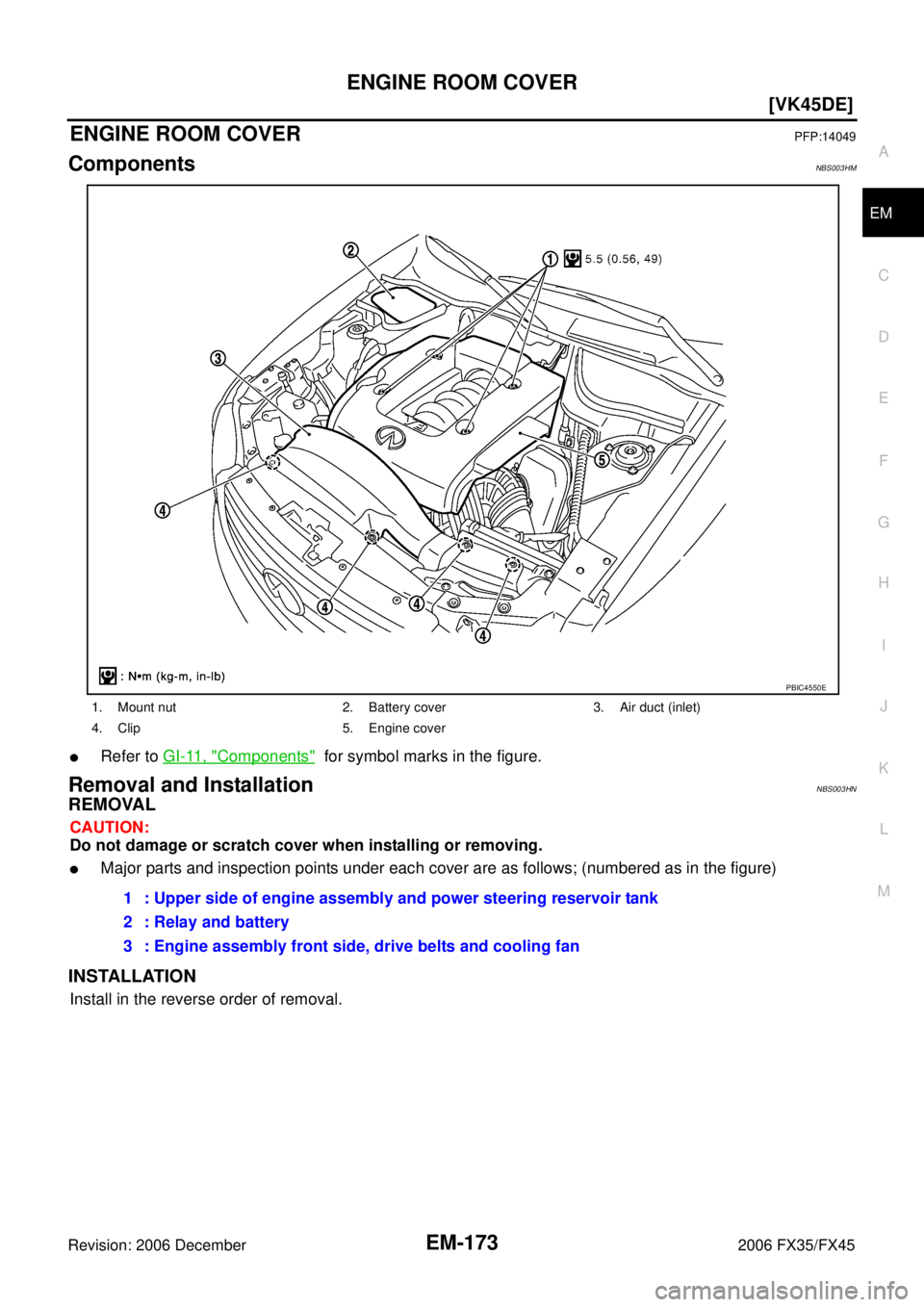
ENGINE ROOM COVERPFP:14049
ComponentsNBS003HM
�Refer to GI-11, "Components" for symbol marks in the figure.
Removal and InstallationNBS003HN
REMOVAL
CAUTION:
Do not damage or scratch cover when installing or removing.
�Major parts and inspection points under each cover are as follows; (numbered as in the figure)
INSTALLATION
Install in the reverse order of removal.
1. Mount nut 2. Battery cover 3. Air duct (inlet)
4. Clip 5. Engine cover
PBIC4550E
1 : Upper side of engine assembly and power steering reservoir tank
2 : Relay and battery
3 : Engine assembly front side, drive belts and cooling fan
Page 2969 of 4462
![INFINITI FX35 2006 Service Manual DRIVE BELTS EM-175
[VK45DE]
C
D E
F
G H
I
J
K L
M A
EM
Revision: 2006 December 2006 FX35/FX45
3. Under the above condition, insert a metallic bar of approximately 6 mm (0.24 in) in diamete](/manual-img/42/57019/w960_57019-2968.png "INFINITI FX35 2006 Service Manual DRIVE BELTS EM-175
[VK45DE]
C
D E
F
G H
I
J
K L
M A
EM
Revision: 2006 December 2006 FX35/FX45
3. Under the above condition, insert a metallic bar of approximately 6 mm (0.24 in) in diamete")
DRIVE BELTS EM-175
[VK45DE]
C
D E
F
G H
I
J
K L
M A
EM
Revision: 2006 December 2006 FX35/FX45
3. Under the above condition, insert a metallic bar of approximately 6 mm (0.24 in) in diameter (hexagonal bar wrench shown as example in the figure) through the holding boss to lock auto tensioner pulley arm.
�Leave auto tensioner pulley arm locked until belt is installed again.
4. Remove alternator, water pump and A/C compressor belt.
Power Steering Oil Pump Belt
1. Remove air duct (inlet). Refer to EM-177, "AIR CLEANER AND AIR DUCT" .
2. Remove front engine undercover with power tool
3. Remove alternator, water pump and A/C compressor belt. Refer to EM-174, "
Alternator, Water Pump and
A/C Compressor Belt" .
4. While securely holding the hexagonal protrusion part of auto tensioner pulley with box wrench, move wrench handle in the
direction of arrow (loosening direction of tensioner).
CAUTION:
Avoid placing hand in a location where pinching may occur
if holding tool accidentally comes off.
5. Under the above condition, insert a metallic bar of approximately 6 mm (0.24 in) in diameter (hexagonal bar wrench shown as
example in the figure) through the holding boss to lock auto ten-
sioner pulley arm.
�Leave auto tensioner pulley arm locked until belt is installed
again.
6. Remove power steering oil pump belt.
INSTALLATION
Note the following, and install in the reverse order of removal.
CAUTION:
�Make sure belt is securely installed around all pulleys.
�Make sure belt is correctly engaged with the pulley groove.
�Check for engine oil and engine coolant are not adhered belt and pulley groove.
�Check that belt tension is within the allowable working range, using indicator notch on auto ten-
sioner. Refer to EM-174, "
Checking Drive Belts" .
PBIC1543E
Page 2974 of 4462
![INFINITI FX35 2006 Service Manual EM-180
[VK45DE]
INTAKE MANIFOLD
Revision: 2006 December 2006 FX35/FX45
�Refer to GI-11, "Components" for symbol marks in the figure.
Removal and InstallationNBS004LY
REMOVAL
WARNING:
To avoid the](/manual-img/42/57019/w960_57019-2973.png "INFINITI FX35 2006 Service Manual EM-180
[VK45DE]
INTAKE MANIFOLD
Revision: 2006 December 2006 FX35/FX45
�Refer to GI-11, \"Components\" for symbol marks in the figure.
Removal and InstallationNBS004LY
REMOVAL
WARNING:
To avoid the")
EM-180
[VK45DE]
INTAKE MANIFOLD
Revision: 2006 December 2006 FX35/FX45
�Refer to GI-11, "Components" for symbol marks in the figure.
Removal and InstallationNBS004LY
REMOVAL
WARNING:
To avoid the danger of being scalded, never drain the engine coolant when the engine is hot.
1. Remove engine cover with power tool.
2. Release fuel pressure. Refer to EC-746, "
FUEL PRESSURE RELEASE" .
3. Remove air duct (inlet), power duct, air cleaner case and air duct and resonator assembly. Refer to EM-
177, "AIR CLEANER AND AIR DUCT" .
4. Drain engine coolant from radiator. Refer to CO-38, "
DRAINING ENGINE COOLANT" .
CAUTION:
�Perform this step when the engine is cold.
�Do not spill engine coolant on drive belts.
1. PCV tube 2. PCV hose 3. PCV hose
4. Engine cover bracket (RH) 5. EVAP canister purge control sole-
noid valve 6. EVAP hose
7. EVAP service port 8. EVAP tube 9. Vacuum hose
10. Vacuum hose 11. PCV hose 12. PCV tube
13. PCV hose 14. PCV hose 15. Water hose
16. EVAP hose 17. Water hose 18. Intake manifold adapter
19. Gasket 20. Electric throttle control actuator 21. Gasket
22. Gasket 23. Intake manifold (lower) 24. Vacuum hose
25. VIAS control solenoid valve 26. Vacuum hose 27. Vacuum hose
28. Vacuum tank 29. Vacuum hose 30. Engine cover bracket (LH)
31. Vacuum hose 32. Water hose 33. Gasket
34. Intake manifold (upper)
A. To centralized under-floor piping B. To rocker cover (right bank) C. To rocker cover (left bank)
D. To thermostat housing E. To air duct and resonator assembly F. To heater pipe
PBIC4553E
Page 2977 of 4462
![INFINITI FX35 2006 Service Manual EXHAUST MANIFOLD AND THREE WAY CATALYST EM-183
[VK45DE]
C
D E
F
G H
I
J
K L
M A
EM
Revision: 2006 December 2006 FX35/FX45
EXHAUST MANIFOLD AND THREE WAY CATALYSTPFP:14004
ComponentsNBS003H](/manual-img/42/57019/w960_57019-2976.png "INFINITI FX35 2006 Service Manual EXHAUST MANIFOLD AND THREE WAY CATALYST EM-183
[VK45DE]
C
D E
F
G H
I
J
K L
M A
EM
Revision: 2006 December 2006 FX35/FX45
EXHAUST MANIFOLD AND THREE WAY CATALYSTPFP:14004
ComponentsNBS003H")
EXHAUST MANIFOLD AND THREE WAY CATALYST EM-183
[VK45DE]
C
D E
F
G H
I
J
K L
M A
EM
Revision: 2006 December 2006 FX35/FX45
EXHAUST MANIFOLD AND THREE WAY CATALYSTPFP:14004
ComponentsNBS003HZ
�Refer to GI-11, "Components" for symbol marks in the figure.
Removal and InstallationNBS003I0
REMOVAL
WARNING:
Perform the work, when the exhaust and cooling system have completely cooled down.
1. Remove engine cover with power tool. Refer to EM-173, "
ENGINE ROOM COVER" .
2. Remove front and rear engine undercovers with power tool.
3. Remove air duct (inlet), air cleaner case and mass air flow sensor assembly, air duct and resonator assembly. Refer to EM-177, "
AIR CLEANER AND AIR DUCT" .
4. Remove front cross bar. Refer to FSU-6, "
FRONT SUSPENSION ASSEMBLY" .
5. Drain engine coolant from radiator. Refer to CO-38, "
Changing Engine Coolant" .
CAUTION:
�Perform this step when engine is cold.
�Do not spill engine coolant on drive belts.
6. Remove radiator. Refer to CO-41, "
RADIATOR" .
1. Air fuel ratio sensor 1 (bank 2) 2. Exhaust manifold cover (right bank) 3. Exhaust manifold (right bank)
4. Gasket 5. Exhaust manifold (left bank) 6. Exhaust manifold cover (left bank)
7. Air fuel ratio sensor 1 (bank 1) 8. Three way catalyst cover (right bank) 9. Three way catalyst (right bank)
10. Heated oxygen sensor 2 (bank 2) 11. Gasket 12. Three way catalyst cover (left bank)
13. Heated oxygen sensor 2 (bank 1) 14. Three way catalyst (left bank) 15. Mounting bracket
16. Mounting bracket
A. Protrusion for installation confirma-
tion.
:Above
PBIC4549E
Page 2981 of 4462
![INFINITI FX35 2006 Service Manual OIL PAN AND OIL STRAINER EM-187
[VK45DE]
C
D E
F
G H
I
J
K L
M A
EM
Revision: 2006 December 2006 FX35/FX45
OIL PAN AND OIL STRAINERP F P : 1111 0
ComponentsNBS003I1
�Refer to GI-11, "Com](/manual-img/42/57019/w960_57019-2980.png "INFINITI FX35 2006 Service Manual OIL PAN AND OIL STRAINER EM-187
[VK45DE]
C
D E
F
G H
I
J
K L
M A
EM
Revision: 2006 December 2006 FX35/FX45
OIL PAN AND OIL STRAINERP F P : 1111 0
ComponentsNBS003I1
�Refer to GI-11, \"Com")
OIL PAN AND OIL STRAINER EM-187
[VK45DE]
C
D E
F
G H
I
J
K L
M A
EM
Revision: 2006 December 2006 FX35/FX45
OIL PAN AND OIL STRAINERP F P : 1111 0
ComponentsNBS003I1
�Refer to GI-11, "Components" for symbol marks in the figure.
Removal and InstallationNBS003I2
REMOVAL
WARNING:
To avoid the danger of being scalded, do not drain engine oil when engine is hot.
1. Remove front road wheels and tires.
2. Remove hood assembly. Refer to BL-13, "
HOOD" .
3. Remove engine cover with power tool. Refer to EM-173, "
ENGINE ROOM COVER" .
4. Remove front and rear engine undercovers with power tool.
5. Drain engine oil. Refer to LU-27, "
Changing Engine Oil" .
CAUTION:
�Perform this step when engine is cold.
1. Oil pan 2. O-ring 3. Crankshaft position sensor (POS)
4. Baffle plate 5. O-ring 6. Baffle plate
7. Oil pressure switch 8. Gasket 9. Oil strainer
10. Drain plug 11. Drain plug washer 12. O-ring
13. Oil cooler 14. Connector bolt 15. Oil filter
16. O-ring 17. Axle pipe 18. O-ring
19. Rear plate cover 20. Relief valve
A. Oil pan side B. Refer to LU-29
C. Refer to LU-28
PBIC4556E
Page 2982 of 4462
![INFINITI FX35 2006 Service Manual EM-188
[VK45DE]
OIL PAN AND OIL STRAINER
Revision: 2006 December 2006 FX35/FX45
�Do not spill engine oil on drive belts.
6. Drain engine coolant. Refer to CO-38, "
Changing Engine Coolant" .
CAUTI](/manual-img/42/57019/w960_57019-2981.png "INFINITI FX35 2006 Service Manual EM-188
[VK45DE]
OIL PAN AND OIL STRAINER
Revision: 2006 December 2006 FX35/FX45
�Do not spill engine oil on drive belts.
6. Drain engine coolant. Refer to CO-38, \"
Changing Engine Coolant\" .
CAUTI")
EM-188
[VK45DE]
OIL PAN AND OIL STRAINER
Revision: 2006 December 2006 FX35/FX45
�Do not spill engine oil on drive belts.
6. Drain engine coolant. Refer to CO-38, "
Changing Engine Coolant" .
CAUTION:
�Perform this step when engine is cold.
�Do not spill engine coolant on drive belts.
7. Remove drive belts. Refer to EM-174, "
DRIVE BELTS" .
8. Remove auto tensioner of power steering oil pump belt. Refer to EM-176, "
Drive Belt Auto Tensioner and
Idler Pulley" .
9. Remove power steering oil pump with piping connected, and temporarily secure it aside with ropes or equivalent. Refer to PS-29, "
POWER STEERING OIL PUMP" .
10. Remove A/C compressor with piping connected, and temporarily secure it aside with ropes or equivalent. Refer to ATC-139, "
Components" .
11. Remove A/C compressor fitting bolts, and install A/C compressor temporarily on vehicle side with ropes or equivalent.
12. Remove harness of lower side of oil pan.
13. Remove crankshaft position sensor (POS) from transmission. CAUTION:
�Handle carefully to avoid dropping and shocks.
�Do not disassemble it.
�Do not allow metal powder to adhere to magnetic part at sensor tip.
�Do not place sensors in a location where they are exposed to magnetism.
14. Install engine slinger and hang engine assembly to secure position. Refer to EM-243, "
ENGINE ASSEM-
BLY" .
15. Remove front suspension member with power tool. Refer to FSU-17, "
FRONT SUSPENSION MEMBER" .
16. Remove front final drive assembly. Refer to FFD-13, "
FRONT FINAL DRIVE ASSEMBLY" .
17. Remove oil filter. Refer to LU-28, "
OIL FILTER" .
18. Disconnect oil cooler water hoses, and remove oil cooler water pipe and oil cooler. Refer to LU-29, "
OIL
COOLER" .
19. Remove oil pan as the follows:
a. Remove rear plate cover.
b. Remove transmission joint bolts which pierce oil pan. Refer to AT- 2 6 9 , "
Removal and Installation (AWD
Models)" .
c. Loosen mounting bolts with power tool in reverse order as shown in the figure.
NOTE:
Disregard the numerical order No. 11 and 17 in removal.
PBIC0194E
Page 2988 of 4462
![INFINITI FX35 2006 Service Manual EM-194
[VK45DE]
FUEL INJECTOR AND FUEL TUBE
Revision: 2006 December 2006 FX35/FX45
FUEL INJECTOR AND FUEL TUBEPFP:16600
ComponentsNBS004LZ
CAUTION:
Do not remove or disassemble parts unless instructe](/manual-img/42/57019/w960_57019-2987.png "INFINITI FX35 2006 Service Manual EM-194
[VK45DE]
FUEL INJECTOR AND FUEL TUBE
Revision: 2006 December 2006 FX35/FX45
FUEL INJECTOR AND FUEL TUBEPFP:16600
ComponentsNBS004LZ
CAUTION:
Do not remove or disassemble parts unless instructe")
EM-194
[VK45DE]
FUEL INJECTOR AND FUEL TUBE
Revision: 2006 December 2006 FX35/FX45
FUEL INJECTOR AND FUEL TUBEPFP:16600
ComponentsNBS004LZ
CAUTION:
Do not remove or disassemble parts unless instructed as shown in the figure.
�Refer to GI-11, "Components" for symbol marks in the figure.
Removal and InstallationNBS004M0
REMOVAL
WARNING:
�Put a “CAUTION FLAMMABLE” sign in the workshop.
�Be sure to work in a well ventilated area and furnish workshop with a CO2 fire extinguisher.
�Do not smoke while servicing fuel system. Keep open flames and sparks away from the work area.
�To avoid the danger of being scalded, do not drain engine coolant when engine is hot.
1. Remove engine cover with power tool. Refer to EM-179, "
INTAKE MANIFOLD" .
2. Release fuel pressure. Refer to EC-746, "
FUEL PRESSURE RELEASE" .
1. Fuel feed hose 2. Fuel feed hose bracket 3. Centralized under-floor piping
4. Quick connector cap 5. O-ring 6. Fuel tube (RH)
7. Spacer 8. Fuel feed damper 9. Fuel damper and fuel hose assembly
10. Clip 11. O-ring (Green) 12. Fuel injector
13. O-ring (Black) 14. Fuel tube (LH)
A. Refer to EM-194
PBIC4554E
![INFINITI FX35 2006 Service Manual EM-166
[VK45DE]
PRECAUTIONS
Revision: 2006 December 2006 FX35/FX45
3. Attach liquid gasket tube to tube presser [SST: WS39930000 (—)].
Use Genuine RTV Silicone Sealant or equivalent. Refer to
GI-48,](/manual-img/42/57019/w960_57019-2959.png "INFINITI FX35 2006 Service Manual EM-166
[VK45DE]
PRECAUTIONS
Revision: 2006 December 2006 FX35/FX45
3. Attach liquid gasket tube to tube presser [SST: WS39930000 (—)].
Use Genuine RTV Silicone Sealant or equivalent. Refer to
GI-48,")