Page 3989 of 4462
HYDRAULIC LINE PS-41
C
D E
F
H I
J
K L
M A
B
PS
Revision: 2006 December 2006 FX35/FX45
Removal and InstallationNGS000CB
�Refer to PS-39, "Components" for tightening torque. Install in the reverse order of removal.
NOTE:
Refer to component parts location and do not reuse non-reusable parts.
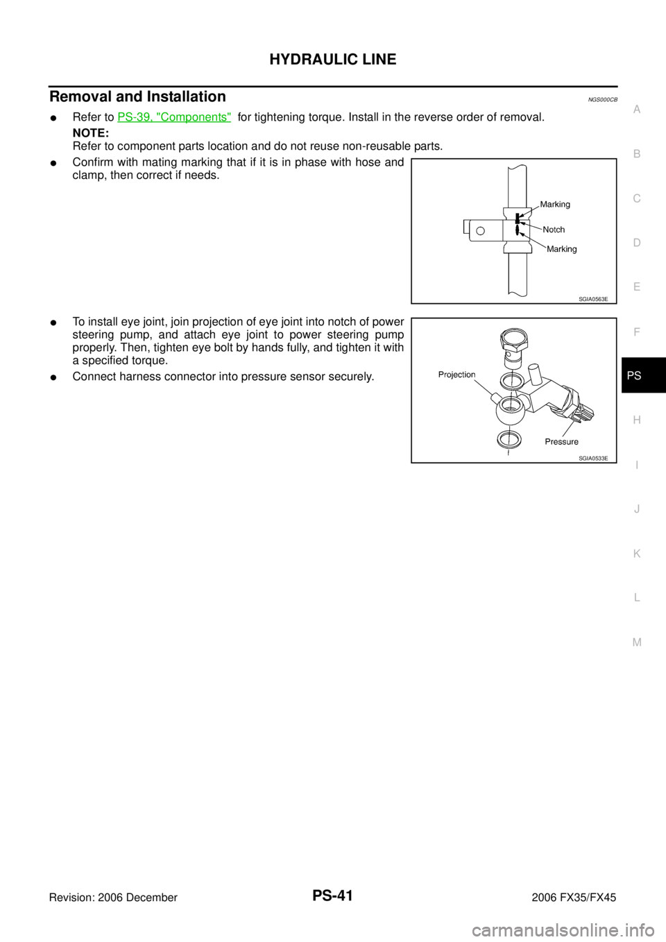
�Confirm with mating marking that if it is in phase with hose and
clamp, then correct if needs.
�To install eye joint, join projection of eye joint into notch of power
steering pump, and attach eye joint to power steering pump
properly. Then, tighten eye bolt by hands fully, and tighten it with
a specified torque.
�Connect harness connector into pressure sensor securely.
SGIA0563E
SGIA0533E
Page 3991 of 4462
HYDRAULIC LINE PS-43
C
D E
F
H I
J
K L
M A
B
PS
Revision: 2006 December 2006 FX35/FX45
Removal and InstallationNGS000CD
�Refer to PS-39, "Components" for tightening torque. Install in the reverse order of removal.
NOTE:
Refer to component parts location and do not reuse non-reusable parts.
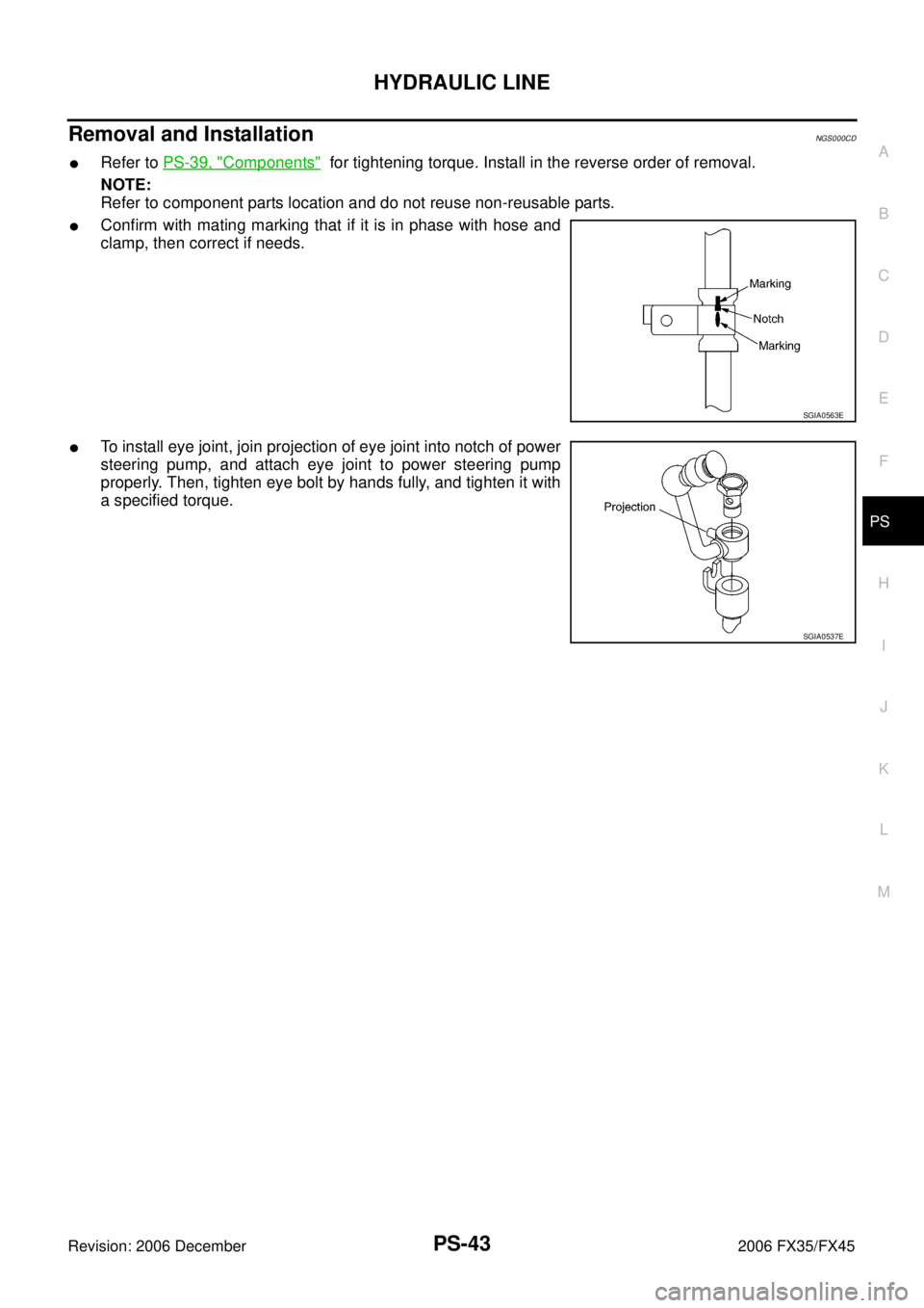
�Confirm with mating marking that if it is in phase with hose and
clamp, then correct if needs.
�To install eye joint, join projection of eye joint into notch of power
steering pump, and attach eye joint to power steering pump
properly. Then, tighten eye bolt by hands fully, and tighten it with
a specified torque.
SGIA0563E
SGIA0537E
Page 3993 of 4462
SERVICE DATA AND SPECIFICATIONS (SDS) PS-45
C
D E
F
H I
J
K L
M A
B
PS
Revision: 2006 December 2006 FX35/FX45
Steering GearNGS000CI
Oil PumpNGS000CJ
Steering FluidNGS000CK
Tie-rod length “L” 135.2 mm (5.32 in)
SGIA0167E
Steering gear model PR26AM
Rack neutral position, dimension “L” (rack stroke) 67.0 mm (2.64 in)
Rack sliding force At the neutral point:
Range within ± 11.5 mm
( ± 0.453 in) from the neutral
position
(in power ON) Area average value 147
− 211 N (15 − 21.5 kg, 33 − 47 lb)
Allowable variation 98 N (10 kg, 22 lb) or less
Whole area (in power OFF) Peak value 294 N (30 kg, 66 lb) or less
Allowable variation 147 N (15 kg, 33 lb) or less
SGIA0629J
Oil pump relief hydraulic pressure 9,900 − 10,700 kPa (101 − 109.1 kg/cm2 , 1436 − 1552 psi)
Fluid capacity
Approx. 1.0 (1-1/8 US qt, 7/8 Imp qt)
Page 4000 of 4462

RAX-6
REAR WHEEL HUB AND KNUCKLE
Revision: 2006 December 2006 FX35/FX45
9. Remove parking brake cable and parking brake shoe from back plate. Refer to PB-6, "PARKING BRAKE
SHOE" and PB-4, "PARKING BRAKE CONTROL" .
10. Remove fixing nuts of anchor block with power tool, then remove anchor block and back plate from axle.
11. Loosen fixing bolts and nuts of front lower link, radius rod, and rear lower link in side of suspension mem- ber.
12. Set jack under rear lower link. Then remove fixing bolt in front lower link side of shock absorber with power tool.
13. Remove bolt and nut in axle side of rear lower link with power tool. Then remove coil spring. Refer to RSU-15, "
REAR LOWER LINK & COIL SPRING" .
14. Remove fixing bolts and nuts in axle side of front lower link, radius rod with power tool.
15. Remove suspension arm and cotter pin at axle, then loosen mounting nut.
16. Use a ball joint remover (suitable tool) to remove suspension arm from axle. Be careful not to damage ball joint boot.
CAUTION:
Tighten temporarily mounting nut to prevent damage to threads and to prevent ball joint remover
(suitable tool) from coming off.
17. Remove axle from vehicle.
INSPECTION AFTER REMOVAL
Check for deformity, cracks and damage on each parts, replace if necessary.
Ball Joint Inspection
Check for boot breakage, axial looseness, and torque of suspension arm ball joint. Refer to RSU-11,
"INSPECTION AFTER REMOVAL" .
INSTALLATION
�Refer to RAX-5, "Removal and Installation" for tightening torque. Install in the reverse order of removal.
NOTE:
Refer to component parts location and do not reuse non-reusable parts.
�Perform final tightening of installation position of suspension links (rubber bushing) under unladen condi-
tions with tires on level ground, Check wheel alignment. Refer to RSU-5, "
Wheel Alignment Inspection" .
�After adjusting wheel alignment, adjust neutral position of steering angle sensor. Refer to BRC-6, "Adjust-
ment of Steering Angle Sensor Neutral Position" .
Page 4003 of 4462

REAR DRIVE SHAFT RAX-9
C E F
G H
I
J
K L
M A
B
RAX
Revision: 2006 December 2006 FX35/FX45
REAR DRIVE SHAFTPFP:39600
Removal and InstallationNDS000CK
COMPONENTS
REMOVAL
1. Remove tires from vehicle with power tool.
2. Remove cotter pin. Then remove lock nut from drive shaft.
3. Remove fixing nuts and bolts between side flange and drive shaft with power tool.
4. Using a puller (suitable tool), remove drive shaft from steering knuckle.
CAUTION:
When removing drive shaft, do not apply an excessive
angle to drive shaft joint.Also be careful not to excessively
extend slide joint.
5. Remove drive shaft from axle.
INSPECTION AFTER REMOVAL
�Move joint up/down, left/right, and in the axial direction. Check
for any rough movement or significant looseness.
�Check boot for cracks or other damage, and also for grease
leakage.
�If a trouble is found, disassemble drive shaft, and then replace
with new one.
INSTALLATION
Refer to RAX-9, "Removal and Installation" for tightening torque. Install in the reverse order of removal.
NOTE:
Refer to component parts location and do not reuse non-reusable parts.
1. Side flange 2. Cotter pin
SDIA1487E
SDIA0972J
RAA0030D
Page 4084 of 4462

RSU-8
REAR SUSPENSION ASSEMBLY
Revision: 2006 December 2006 FX35/FX45
REMOVAL
1. Remove tires from vehicle with power tool.
2. Remove brake caliper with power tool. Hang it in a place where it will not interfere with work. Refer to BR-
25, "REAR DISC BRAKE" .
NOTE:
Avoid depressing brake pedal while brake caliper is removed.
3. Remove wheel sensor from rear final drive, then remove wheel sensor harness from rear suspension member.
4. Remove height sensor harness from rear suspension member (if equipped).
5. Remove center muffler and main muffler. Refer to EX-3, "
Components" .
6. Remove stabilizer bar. Refer to RSU-16, "
Removal and Installation" .
7. Remove rear propeller shaft. Refer to PR-9, "
Removal and Installation" .
8. Separate attachments between parking brake cable and vehicle and rear suspension member.
9. Remove rear lower link and coil spring. Refer to RSU-15, "
Removal and Installation" .
10. Remove fixing bolt in lower side of shock absorber with power tool.
11. Set jack under rear final drive.
12. Remove fixing bolts and nuts of tunnel stay and member stay with power tool, then remove those parts from vehicle.
13. Remove fixing bolts and nuts of rear pin stay with power tool and then remove rear pin stay from vehicle.
14. Gradually lowering jack, remove rear suspension assembly.
INSTALLATION
�Refer to RSU-7, "Removal and installation" for tightening torque. Install in the reverse order of removal.
NOTE:
Refer to component parts location and do not reuse non-reusable parts.
�Perform final tightening of installation position of links (rubber bushing) under unladen conditions with tires
on level ground. Check wheel alignment. Refer to RSU-5, "
Wheel Alignment Inspection" .
�After adjusting wheel alignment, adjust neutral position of steering angle sensor. Refer to BRC-6, "Adjust-
ment of Steering Angle Sensor Neutral Position" .
1. Bushing 2. Mounting seal 3. Mounting seal bracket
4. Distance tube 5. Bound bumper cover 6. Bound bumper
7. Shock absorber 8. Upper seat 9. Coil spring
10. Rubber seat 11. Rear lower link 12. Axle assembly
13. Cotter pin 14. Radius rod 15. Front lower link protector
16. Front lower link 17. Stopper rubber 18. Shock absorber assembly
19. Suspension arm 20. Stabilizer connecting rod mounting bracket 21. Stabilizer connecting rod
22. Rear pin stay 23. Rear suspension member 24. Stabilizer bar
25. Stabilizer bushing 26. Stabilizer clamp 27. Member stay
28. Tunnel stay A: With height sensor B: Without height sensor
Refer to GI-11, "
Components" , for the symbols in the figure.
Page 4085 of 4462

SHOCK ABSORBER RSU-9
C
D
F
G H
I
J
K L
M A
B
RSU
Revision: 2006 December 2006 FX35/FX45
SHOCK ABSORBERPFP:56210
Removal and InstallationNES000G8
REMOVAL
1. Remove tires from vehicle with power tool.
2. Set jack under rear lower link.
3. Remove fixing bolt in lower side of shock absorber assembly with power tool.
4. Remove fixing nuts in upper side of shock absorber assembly with power tool and remove shock absorber assembly from
vehicle.
INSPECTION AFTER REMOVAL
�Check shock absorber assembly for deformation, cracks, or damage, and replace if necessary.
�Check piston rod for damage, uneven wear, or distortion, and replace if necessary.
�Check welded and sealed areas for oil leakage, and replace if necessary.
INSTALLATION
�Refer to RSU-7, "Removal and installation" for tightening torque. Install in the reverse order of removal.
NOTE:
Refer to component parts location and do not reuse non-reusable parts.
�Perform final tightening of shock absorber assembly lower side (rubber bushing) under unladen condi-
tions with tires on level ground. Check wheel alignment. Refer to RSU-5, "
Wheel Alignment Inspection" .
�After adjusting wheel alignment, adjust neutral position of steering angle sensor. Refer to BRC-6, "Adjust-
ment of Steering Angle Sensor Neutral Position" .
Disassembly and AssemblyNES000G9
DISASSEMBLY
CAUTION:
Make sure piston rod on shock absorber is not damaged when removing components from shock
absorber.
1. Remove mounting seal from mounting seal bracket.
2. Wrap a shop cloth around lower side of shock absorber and fix it in a vise.
CAUTION:
Do not set the cylindrical part of shock absorber in vise.
3. Fix piston rod with hexagon wrench, and remove piston rod lock nut.
4. Remove mounting seal bracket, bushing, distance tube, bound bumper cover and bound bumper from shock absorber.
FA-0274D
SEIA0366E
Page 4089 of 4462

RADIUS ROD RSU-13
C
D
F
G H
I
J
K L
M A
B
RSU
Revision: 2006 December 2006 FX35/FX45
RADIUS RODPFP:55110
Removal and InstallationNES000GB
REMOVAL
1. Remove tires from vehicle with power tool.
2. Set jack under rear lower link.
3. Remove fixing bolt and nut in axle side of radius rod.
4. Remove fixing bolt in rear suspension member side of radius rod with power tool, then remove radius rod from vehicle.
INSPECTION AFTER REMOVAL
Check radius rod and bushing for any deformation, cracks, or damage. Replace if necessary.
INSTALLATION
�Refer to RSU-7, "Removal and installation" for tightening torque. Install in the reverse order of removal.
NOTE:
Refer to component parts location and do not reuse non-reusable parts.
�Perform final tightening of rear suspension member and axle installation position (rubber bushing) under
unladen conditions with tires on level ground. Check wheel alignment. Refer to RSU-5, "
Wheel Alignment
Inspection" .
�After adjusting wheel alignment, adjust neutral position of steering angle sensor. Refer to BRC-6, "Adjust-
ment of Steering Angle Sensor Neutral Position" .
 PS-45
C
D E
F
H I
J
K L
M A
B
PS
Revision: 2006 December 2006 FX35/FX45
Steering GearNGS000CI
Oil PumpNGS000CJ
Steering FluidNGS000CK
Tie-rod length �")