Page 3823 of 4462

ENGINE MAINTENANCE (VK45DE ENGINE) MA-23
C
D E
F
G H
I
J
K
M A
B
MA
Revision: 2006 December 2006 FX35/FX45
DRAINING ENGINE COOLANT
1. Remove front engine undercover with power tool.
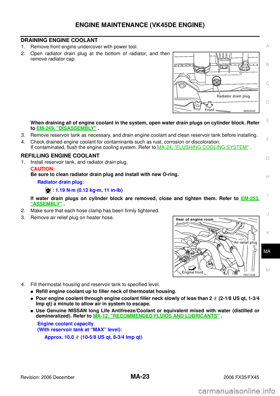
2. Open radiator drain plug at the bottom of radiator, and then remove radiator cap.
When draining all of engine coolant in the system, open water drain plugs on cylinder block. Refer
to EM-249, "
DISASSEMBLY" .
3. Remove reservoir tank as necessary, and drain engine coolant and clean reservoir tank before installing.
4. Check drained engine coolant for contaminants such as rust, corrosion or discoloration. If contaminated, flush the engine cooling system. Refer to MA-24, "
FLUSHING COOLING SYSTEM" .
REFILLING ENGINE COOLANT
1. Install reservoir tank, and radiator drain plug.
CAUTION:
Be sure to clean radiator drain plug and install with new O-ring.
If water drain plugs on cylinder block are removed, close and tighten them. Refer to EM-253,
"ASSEMBLY" .
2. Make sure that each hose clamp has been firmly tightened.
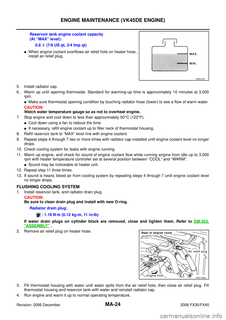
3. Remove air relief plug on heater hose.
4. Fill thermostat housing and reservoir tank to specified level.
�Refill engine coolant up to filler neck of thermostat housing.
�Pour engine coolant through engine coolant filler neck slowly of less than 2 (2-1/8 US qt, 1-3/4
Imp qt) a minute to allow air in system to escape.
�Use Genuine NISSAN long Life Antifreeze/Coolant or equivalent mixed with water (distilled or
demineralized). Refer to MA-12, "
RECOMMENDED FLUIDS AND LUBRICANTS" .
SBIA0444E
Radiator drain plug:
: 1.19 N·m (0.12 kg-m, 11 in-lb)
PBIC1530E
Engine coolant capacity
(With reservoir tank at “MAX” level):
Approx. 10.0 (10-5/8 US qt, 8-3/4 Imp qt)
Page 3824 of 4462

MA-24
ENGINE MAINTENANCE (VK45DE ENGINE)
Revision: 2006 December 2006 FX35/FX45
�When engine coolant overflows air relief hole on heater hose,
install air relief plug.
5. Install radiator cap.
6. Warm up until opening thermostat. Standard for warming-up time is approximately 10 minutes at 3,000 rpm.
�Make sure thermostat opening condition by touching radiator hose (lower) to see a flow of warm water.
CAUTION:
Watch water temperature gauge so as not to overheat engine.
7. Stop engine and cool down to less than approximately 50 °C (122 °F).
�Cool down using a fan to reduce the time.
�If necessary, refill engine coolant up to filler neck of thermostat housing.
8. Refill reservoir tank to “MAX” level line with engine coolant.
9. Repeat steps 4 through 7 two or more times with radiator cap installed until engine coolant level no longer drops.
10. Check cooling system for leaks with engine running.
11. Warm up engine, and check for sound of engine coolant flow while running engine from idle up to 3,000 rpm with heater temperature controller set at several position between “COOL” and “WARM”.
�Sound may be noticeable at heater unit.
12. Repeat step 11 three times.
13. If sound is heard, bleed air from cooling system by repeating steps 4 through 7 until engine coolant level no longer drops.
FLUSHING COOLING SYSTEM
1. Install reservoir tank, and radiator drain plug.
CAUTION:
Be sure to clean drain plug and install with new O-ring.
If water drain plugs on cylinder block are removed, close and tighten them. Refer to EM-253,
"ASSEMBLY" .
2. Remove air relief plug on heater hose.
3. Fill thermostat housing with water until water spills from the air relief hole, then close air relief plug. Fill thermostat housing and reservoir tank with water and reinstall radiator cap.
4. Run engine and warm it up to normal operating temperature. Reservoir tank engine coolant capacity
(At “MAX” level):
0.8 (7/8 US qt, 3/4 lmp qt)
SMA412B
Radiator drain plug:
: 1.19 N·m (0.12 kg-m, 11 in-lb)
PBIC1530E
Page 3917 of 4462

HARNESS PG-65
C
D E
F
G H
I
J
L
M A
B
PG
Revision: 2006 December 2006 FX35/FX45
Wiring Diagram Codes (Cell Codes) NKS003GO
Use the chart below to find out what each wiring diagram code stands for.
Refer to the wiring diagram code in the alphabetical index to find the location (page number) of each wiring
diagram.
Code Section Wiring Diagram Name
A/C ATC Air Conditioner
AF1B1 EC Air Fuel Ratio Sensor 1 Bank 1
AF1B2 EC Air Fuel Ratio Sensor 1 Bank 2
AF1HB1 EC Air Fuel Ratio Sensor 1 Heater Bank 1
AF1HB2 EC Air Fuel Ratio Sensor 1 Heater Bank 2
APPS1 EC Accelerator Pedal Position Sensor
APPS2 EC Accelerator Pedal Position Sensor
APPS3 EC Accelerator Pedal Position Sensor
ASC/BS EC Automatic Speed Control Device (ASCD) Brake Switch
ASC/SW EC Automatic Speed Control Device (ASCD) Steering Switch
ASCBOF EC Automatic Speed Control Device (ASCD) Brake Switch
ASCIND EC Automatic Speed Control Device (ASCD) Indicator
AT/IND DI A/T Indicator Lamp
AUDIO AV Audio
AUT/DP SE Automatic Drive Positioner
AUTO/L LT Automatic Light System
AWD TF AWD Control System
B/CLOS BL Back Door Closure System
BACK/L LT Back-Up Lamp
BRK/SW EC Brake Switch
CAN AT CAN Communication Line
CAN EC CAN Communication Line
CAN LAN CAN System
CHARGE SC Charging System
CHIME DI Warning Chime
CLOCK DI Clock
COMBSW LT Combination Switch
COMM AV Audio Visual Communication Line
COMPAS DI Compass
COOL/F EC Cooling Fan Control
D/LOCK BL Power Door Lock
DEF GW Rear Window Defogger
DTRL LT Headlamp - With Daytime Light System
ECM/PW EC ECM Power Supply for Back-Up
ECTS EC Engine Coolant Temperature Sensor
ETC1 EC Electric Throttle Control Function
ETC2 EC Electric Throttle Control Motor Relay
ETC3 EC Electric Throttle Control Motor
F/FOG LT Front Fog Lamp
F/PUMP EC Fuel Pump
FTS AT A/T Fluid Temperature Sensor Circuit
Page 3918 of 4462

PG-66
HARNESS
Revision: 2006 December 2006 FX35/FX45
FTTS EC Fuel Tank Temperature Sensor
FUELB1 EC Fuel Injection System Function (Bank 1)
FUELB2 EC Fuel Injection System Function (Bank 2)
H/AIM LT Headlamp Aiming Control System
H/LAMP LT Headlamp
H/PHON AV Hands Free Telephone
HORN WW Horn
HSEAT SE Heated Seat
I/KEY BL Intelligent Key System
I/MIRR GW Inside Mirror (Auto Anti-Dazzling Mirror)
IATS EC Intake Air Temperature Sensor
ICC ACS Intelligent Cruise Control System
ICC/BS EC ICC Brake Switch
ICC/SW EC ICC Steering Switch
ICCBOF EC ICC Brake Switch
IGNSYS EC Ignition System
ILL LT Illumination
INF/D AV Vehicle Information and Integrated Switch System
INJECT EC Injector
IVCB1 EC Intake Valve Timing Control Solenoid Valve Bank 1
IVCB2 EC Intake Valve Timing Control Solenoid Valve Bank 2
IVCSB1 EC Intake Valve Timing Control Position Sensor Bank 1
IVCSB2 EC Intake Valve Timing Control Position Sensor Bank 2
IVTB1 EC Intake Valve Timing Control System (Bank 1)
IVTB2 EC Intake Valve Timing Control System (Bank 2)
KEYLES BL Remote Keyless Entry System
KS EC Knock Sensor
LDW DI Lane Departure Warning System
M/ANT AV Manual Antenna
MAFS EC Mass Air Flow Sensor
MAIN AT Main Power Supply and Ground Circuit
MAIN EC Main Power Supply and Ground Circuit
MES AV Mobile Entertainment System
METER DI Speedometer, Tachometer, Temp. and Fuel Gauges
MIL/DL EC MIL & Data Link Connectors
MIRROR GW Power Door Mirror
MMSW AT Manual Mode Switch
NATS BL Nissan Anti-Theft System
NAVI AV Navigation System
NONDTC AT Non-Detective Items
O2H2B1 EC Heated Oxygen Sensor 2 Heater Bank 1
O2H2B2 EC Heated Oxygen Sensor 2 Heater Bank 2
O2S2B1 EC Heated Oxygen Sensor 2 Bank 1
O2S2B2 EC Heated Oxygen Sensor 2 Bank 2 Code Section Wiring Diagram Name
Page 4241 of 4462
FRONT SEAT SE-103
C
D E
F
G H
J
K L
M A
B
SE
Revision: 2006 December 2006 FX35/FX45
6. Remove the heated seat connector.
7. After removing the seatback trim and pad, remove the hog rings to separate the trim, pad, and seatback heater unit.
INSTALLATION OF SEATBACK TRIM AND PAD
Install in the reverse order of removal.
REMOVAL OF SEAT CUSHION TRIM AND PAD
CAUTION:
Do not disassemble the component parts of only front passenger seat in the dotted lines shown in the
figure. Refer to SE-97
.
1. Remove the seat cushion inner finisher.
2. Remove the velcro and retainer.
3. Remove the seat harness connector.
4. Remove the seatback frame.
5. Remove the reclining device assembly.
PIIA6049E
PIIA6052E
PIIA6053E
PIIA6054E
Page 4242 of 4462
SE-104
FRONT SEAT
Revision: 2006 December 2006 FX35/FX45
6. Remove the retainer and clip.
7. After removing the seat cushion trim and pad, remove the hog rings to separate the trim and pad and the seat cushion heater unit.
INSTALLATION OF SEAT CUSHION TRIM AND PAD
Install in the reverse order of removal.
PIIA6055E