Page 972 of 4462
BL-158
BACK DOOR
Revision: 2006 December 2006 FX35/FX45
BACK DOORPFP:90100
Fitting AdjustmentNIS001OD
VERTICAL/LATERAL CLEARANCE ADJUSTMENT
1. With the striker released, loosen the bumper rubber lock nuts.
2. Close the back door lightly and adjust the surface height by rotating the bumper rubber and, then open the back door to finally tighten the back door lock mounting bolts and bumper rubber lock nuts to the specified
torque.
Back Door AssemblyNIS001OE
REMOVAL
1. Remove roof rear garnish assembly. Refer to EI-44, "Removal and Installation" .
2. Disconnect the back door harness connector and AV antenna feeder.
3. Washer hose is separated in the connection part.
4. Support the back door lock with a proper material to prevent it from falling.
WARNING:
Body injury may occur if no supporting rod is holding the
back door open when removing the damper stay.
1. Bumper rubber 2. Back door striker 3. Screw
PIIB0208E
PIIA6028E
PIIA6061E
Page 973 of 4462
BACK DOOR BL-159
C
D E
F
G H
J
K L
M A
B
BL
Revision: 2006 December 2006 FX35/FX45
5. Remove back door stay on back door.
6. Remove back door hinge mounting nuts on the back door and remove back door assembly.
INSTALLATION
Install in the reverse order of removal.
CAUTION:
�After installing, check operation.
�After installing, perform fitting adjustment. Refer to BL-158, "Fitting Adjustment" .
INSPECTION
1. Check back door hinges for the following.
�Malfunction noise or door closing and opening effort
�Component wear or damage
2. Apply body grease to the rotating part of the back door hinge.
Removal and Installation of Back Door StrikerNIS001OF
REMOVAL
1. Remove rear plate assembly. Refer to EI-44, "Removal and
Installation" .
2. Remove back door striker mounting screws, and remove back door striker from the vehicle.
INSTALLATION
Install in the reverse order of removal.
PIIA6029E
PIIA6030E
PIIA6030E
PIIA9325E
Page 974 of 4462
BL-160
BACK DOOR
Revision: 2006 December 2006 FX35/FX45
CAUTION:
After installing, perform fitting adjustment. Refer to BL-158, "
Fitting Adjustment" .
Removal and Installation of Back Door StayNIS001OG
REMOVAL
1. Support the back door lock with a proper material to prevent it
from falling.
WARNING:
Body injury may occur if no supporting rod is holding the
back door open when removing the damper stay.
2. Remove back door stay on back door.
3. Remove back door stay assembly on vehicle.
INSTALLATION
Install in the reverse order of removal.
CAUTION:
After installing, check operation.
Removal and Installation of Dave Tail Male & FemaleNIS001OH
REMOVAL
1. Remove the dave tail male.
PIIA6061E
PIIA6029E
PIIA6031E
PIIA6078E
Page 975 of 4462
BACK DOOR BL-161
C
D E
F
G H
J
K L
M A
B
BL
Revision: 2006 December 2006 FX35/FX45
2. Remove the rear bumper. Refer to EI-17, "Removal and Installation" .
3. Remove the dave tail female.
INSTALLATION
Install in the reverse order of removal.
Removal and Installation of Back Door WeatherstripNIS001OI
REMOVAL
Pull up and remove engagement with body from weatherstrip joint.
CAUTION:
After removal, do not pull strongly on the weatherstrip.
INSTALLATION
1. Working from the upper section, align weatherstrip mark with vehicle center position mark and install weatherstrip onto the vehicle.
2. For the lower section, align the weatherstrip seam with center of the striker.
3. After installation, pull the weatherstrip gently to ensure that there is no loose section. NOTE:
Make sure the weatherstrip is fit fightly at each corner and back door rear plate.
PIIA6079E
1. Weatherstrip
PIIA6032E
Page 976 of 4462

BL-162
BACK DOOR LOCK ASSEMBLY
Revision: 2006 December 2006 FX35/FX45
BACK DOOR LOCK ASSEMBLYPFP:90504
Removal and Installation of Back Door Lock & Closure AssemblyNIS001OJ
REMOVAL
1. Remove back door finisher. Refer to EI-46, "Removal and Installation" .
2. Disconnect the connector and the clip of the back door lock & closure assembly.
3. Remove the mounting bolts.
4. Disconnect the connector of the back door opener actuator.
5. Remove the mounting bolts, remove back door lock & closure assembly.
INSTALLATION
Install in the reverse order of removal.
CAUTION:
�After installing, check operation.
�After installing, perform fitting adjustment. Refer to BL-158, "Fitting Adjustment" .
INSPECTION
1. Check back door lock for the following.
�Malfunction noise or door closing and opening effort
�Component wear or damage
2. Apply body grease to the rotating part of the back door lock.
Removal and Installation of Back Door Opener SwitchNIS001OK
REMOVAL
1. Remove back door finisher. Refer to EI-46, "Removal and Installation" .
2. Remove back door outside finisher. Refer to EI-46, "
BACK DOOR TRIM" .
3. Remove licence lamp. Refer to LT- 1 5 2 , "
License Plate Lamp" .
4. Cut back door inner panel along with cutting groove line. CAUTION:
When cutting the back door panel, always wear safety
glasses, heavy gloves and a dust proof mask to prevent eye
and skin irritation from glass fiver splinters.
1. Bolt 2. Back door lock & closure assembly
PIIA6043E
PIIA6903E
Page 977 of 4462
BACK DOOR LOCK ASSEMBLY BL-163
C
D E
F
G H
J
K L
M A
B
BL
Revision: 2006 December 2006 FX35/FX45
NOTE:
Through hole is as shown in the figure.
5. Disconnect back door opener switch harness connector (and rear view camera if equipped).
6. Remove opener switch from back door through hole.
INSTALLATION
Install in the reverse order of removal.
CAUTION:
After installing, check operation.
Disassembly and AssemblyNIS001OL
BACK DOOR LOCK & CLOSURE ASSEMBLY
CAUTION:
Be sure to remove or install the back door closure motor with the back door lock & closure assembly.
1. Remove the back door closure motor.
PIIB1645E
PIIB1647E
PIIA6080E
Page 993 of 4462

BACK DOOR AUTO CLOSURE SYSTEM BL-179
C
D E
F
G H
J
K L
M A
B
BL
Revision: 2006 December 2006 FX35/FX45
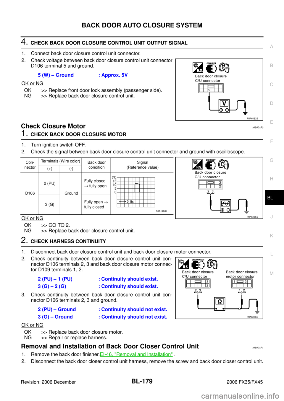
4. CHECK BACK DOOR CLOSURE CONTROL UNIT OUTPUT SIGNAL
1. Connect back door closure control unit connector.
2. Check voltage between back door closure control unit connector D106 terminal 5 and ground.
OK or NG
OK >> Replace front door lock assembly (passenger side).
NG >> Replace back door closure control unit.
Check Closure MotorNIS001P0
1. CHECK BACK DOOR CLOSURE MOTOR
1. Turn ignition switch OFF.
2. Check the signal between back door closure control unit connector and ground with oscilloscope.
OK or NG
OK >> GO TO 2.
NG >> Replace back door closure control unit.
2. CHECK HARNESS CONTINUITY
1. Disconnect back door closure control unit and back door closure motor connector.
2. Check continuity between back door closure control unit con- nector D106 terminals 2, 3 and back door closure motor connec-
tor D109 terminals 1, 2.
3. Check continuity between back door closure control unit con- nector D106 terminals 2, 3 and ground.
OK or NG
OK >> Replace back door closure motor.
NG >> Repair or replace harness.
Removal and Installation of Back Door Closer Control UnitNIS001P1
1. Remove the back door finisher. EI-46, "Removal and Installation" .
2. Disconnect the back door closer control unit harness, remove the screw and back door closer control unit. 5 (W) – Ground : Approx. 5V
PIIA6182E
Con-
nector Terminals (Wire color)
Back door
condition Signal
(Reference value)
(+) (-)
D106 2 (PU)
Ground Fully closed
→ fully open
3 (G) Fully open
→
fully closed
PIIA6185E
SIIA1480J
2 (PU) – 1 (PU) : Continuity should exist.
3 (G) – 2 (G) : Continuity should exist.
2 (PU) – Ground : Continuity should not exist.
3 (G) – Ground : Continuity should not exist.
PIIA6186E
Page 1037 of 4462

IVIS (INFINITI VEHICLE IMMOBILIZER SYSTEM-NATS) BL-223
C
D E
F
G H
J
K L
M A
B
BL
Revision: 2006 December 2006 FX35/FX45
4. PERFORM INITIALIZATION WITH CONSULT-II AGAIN
1. Replace BCM.
2. Perform initialization with CONSULT-II. For initialization, refer to “CONSULT-II Operation Manual NATS-
IVIS/NVIS”.
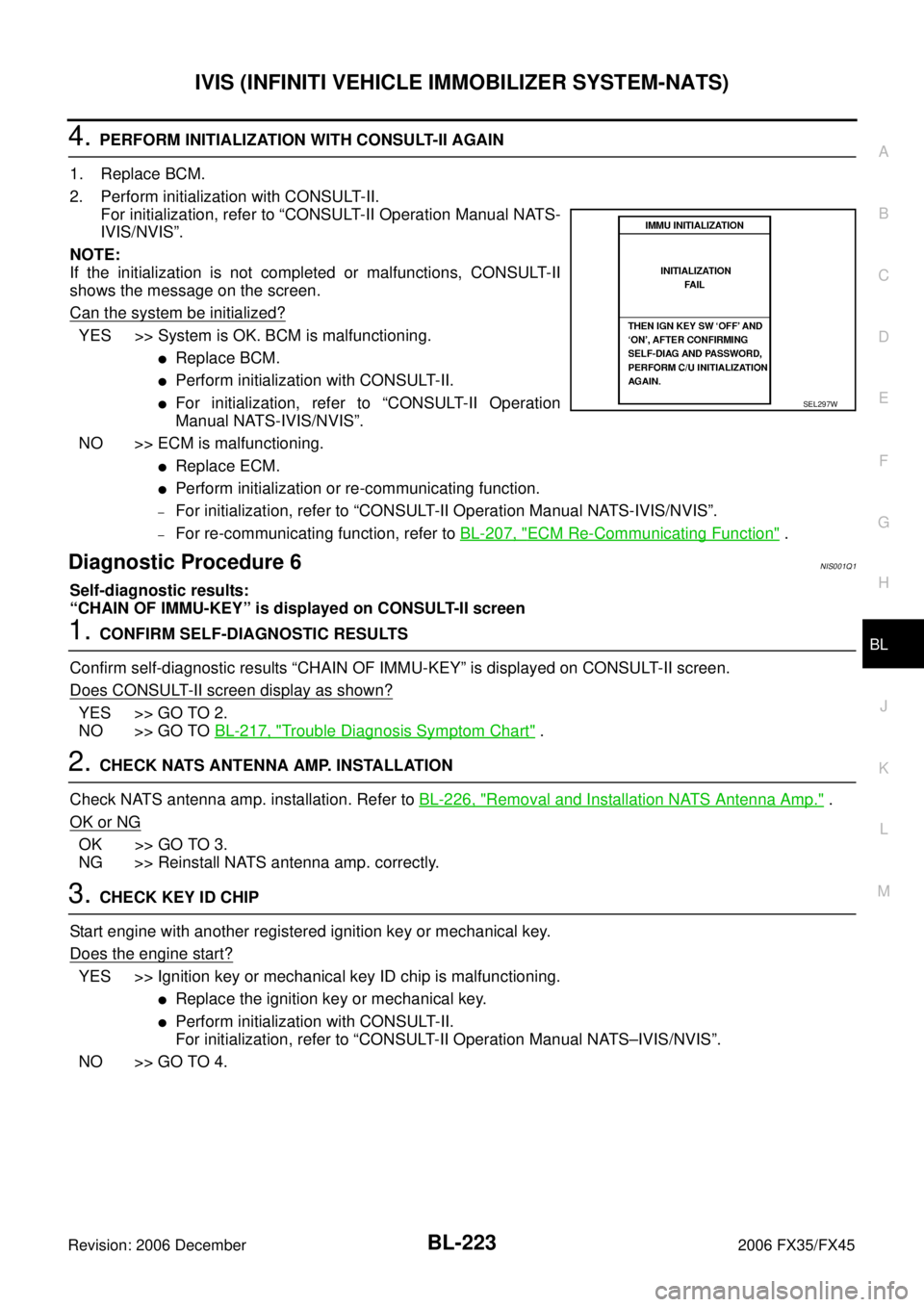
NOTE:
If the initialization is not completed or malfunctions, CONSULT-II
shows the message on the screen.
Can the system be initialized?
YES >> System is OK. BCM is malfunctioning.
�Replace BCM.
�Perform initialization with CONSULT-II.
�For initialization, refer to “CONSULT-II Operation
Manual NATS-IVIS/NVIS”.
NO >> ECM is malfunctioning.
�Replace ECM.
�Perform initialization or re-communicating function.
–For initialization, refer to “CONSULT-II Operation Manual NATS-IVIS/NVIS”.
–For re-communicating function, refer to BL-207, "ECM Re-Communicating Function" .
Diagnostic Procedure 6NIS001Q1
Self-diagnostic results:
“CHAIN OF IMMU-KEY” is displayed on CONSULT-II screen
1. CONFIRM SELF-DIAGNOSTIC RESULTS
Confirm self-diagnostic results “CHAIN OF IMMU-KEY” is displayed on CONSULT-II screen.
Does CONSULT-II screen display as shown?
YES >> GO TO 2.
NO >> GO TO BL-217, "
Trouble Diagnosis Symptom Chart" .
2. CHECK NATS ANTENNA AMP. INSTALLATION
Check NATS antenna amp. installation. Refer to BL-226, "
Removal and Installation NATS Antenna Amp." .
OK or NG
OK >> GO TO 3.
NG >> Reinstall NATS antenna amp. correctly.
3. CHECK KEY ID CHIP
Start engine with another registered ignition key or mechanical key.
Does the engine start?
YES >> Ignition key or mechanical key ID chip is malfunctioning.
�Replace the ignition key or mechanical key.
�Perform initialization with CONSULT-II.
For initialization, refer to “CONSULT-II Operation Manual NATS–IVIS/NVIS”.
NO >> GO TO 4.
SEL297W