Page 435 of 4462
ASSEMBLY AT-351
D E
F
G H
I
J
K L
M A
B
AT
Revision: 2006 December 2006 FX35/FX45
b. Measure dimension “M1 ”.
c. Measure dimension “M
2 ”.
d. Calculate dimension “M”.
3. Adjust total end play “T
1 ”.
�Select proper thickness of bearing race so that total end play
is within specifications. Refer to “Parts Information” for bear-
ing race selection.
SCIA3126E
SCIA3127E
“M” : Distance between transmission case fitting
surface of oil pump and needle bearing on oil
pump.
M = M
1 – M2
SCIA3125E
T1 = J – M
Total end play “T
1 ”
: 0.25 - 0.55 mm (0.0098 - 0.0217 in)
SCIA2810E
Page 436 of 4462
AT-352
ASSEMBLY
Revision: 2006 December 2006 FX35/FX45
Assembly (2)NCS001IY
1. Install O-ring to oil pump assembly. CAUTION:
�Do not reuse O-ring.
�Apply ATF to O-ring.
2. Install bearing race to oil pump assembly. CAUTION:
Apply petroleum jelly to bearing race.
3. Install oil pump assembly in transmission case. CAUTION:
Apply ATF to oil pump bearing.
4. Apply recommended sealant (Genuine RTV Silicone Sealant or equivalent. Refer to GI-48, "
Recommended Chemical Products
and Sealants" .) to oil pump assembly as shown in the figure.
CAUTION:
Completely remove all moisture, oil and old sealant, etc.
From the oil pump mounting bolts and oil pump mounting
bolt mounting surfaces.
SCIA5172E
SCIA6529E
SCIA2811E
SCIA5321E
Page 437 of 4462
ASSEMBLY AT-353
D E
F
G H
I
J
K L
M A
B
AT
Revision: 2006 December 2006 FX35/FX45
5. Tighten oil pump mounting bolts to specified torque. Refer to AT-
274, "Components" .
CAUTION:
Apply ATF to oil pump bushing.
6. Install O-ring to input clutch assembly. CAUTION:
�Do not reuse O-ring.
�Apply ATF to O-ring.
7. Install converter housing to transmission case, and then tighten converter housing mounting bolts to the specified torque. Refer
to AT- 2 7 4 , "
Components" .
CAUTION:
Do not reuse self-sealing bolt.
8. Make sure that brake band does not close turbine revolution sensor hole.
9. Install control valve with TCM.
a. Connect TCM connector and park/neutral position switch con- nector.
SCIA2300E
SCIA5011E
SCIA3427E
SCIA5034E
SCIA5449E
Page 441 of 4462

ASSEMBLY AT-357
D E
F
G H
I
J
K L
M A
B
AT
Revision: 2006 December 2006 FX35/FX45
15. Install snap ring to A/T assembly harness connector.
16. Install magnets in oil pan.
17. Install oil pan to transmission case.
a. Install oil pan gasket to transmission case. CAUTION:
�Do not reuse oil pan gasket.
�Install it in the direction to align hole positions.
�Complete remove all moisture, oil and old gasket, etc. from oil pan gasket mounting surface.
b. Install oil pan to transmission case. CAUTION:
�Install it so that drain plug comes to the position as
shown in the figure.
�Be careful not to pinch harnesses.
�Completely remove all moisture, oil and old gasket, etc.
from oil pan gasket mounting surface.
c. Tighten oil pan mounting bolts to the specified torque in numeri- cal order shown in the figure after temporarily tightening them.
Refer to AT- 2 7 4 , "
Components" .
CAUTION:
Do not reuse oil pan mounting bolts.
18. Install drain plug to oil pan, and then tighten drain plug mounting bolts to the specified torque. Refer to AT- 2 7 4 , "
Components" .
CAUTION:
Do not reuse drain plug gasket.
SCIA5300E
SCIA5200E
SCIA2308E
SCIA4113E
Page 442 of 4462
AT-358
ASSEMBLY
Revision: 2006 December 2006 FX35/FX45
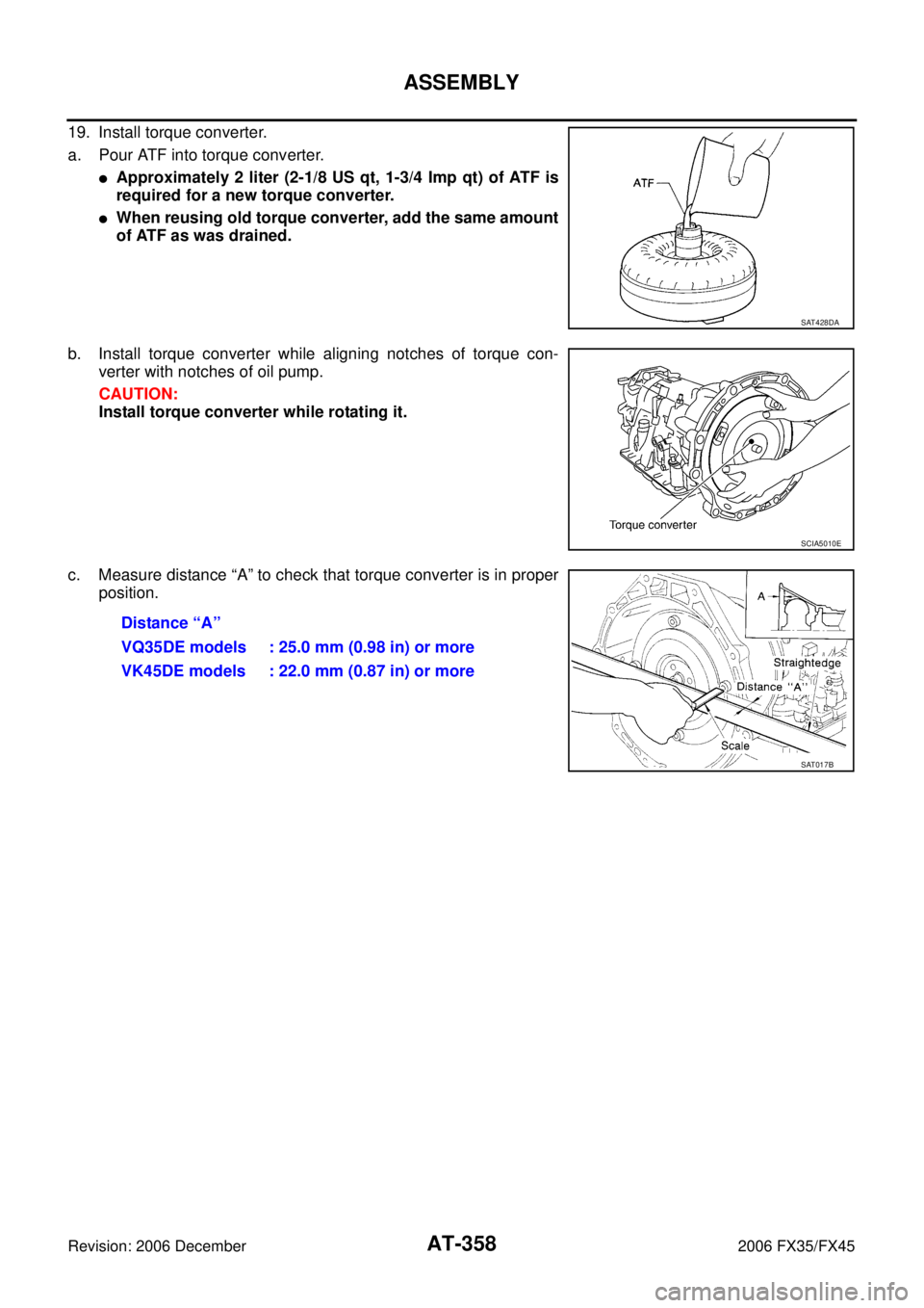
19. Install torque converter.
a. Pour ATF into torque converter.
�Approximately 2 liter (2-1/8 US qt, 1-3/4 Imp qt) of ATF is
required for a new torque converter.
�When reusing old torque converter, add the same amount
of ATF as was drained.
b. Install torque converter while aligning notches of torque con- verter with notches of oil pump.
CAUTION:
Install torque converter while rotating it.
c. Measure distance “A” to check that torque converter is in proper position.
SAT428DA
SCIA5010E
Distance “A”
VQ35DE models : 25.0 mm (0.98 in) or more
VK45DE models : 22.0 mm (0.87 in) or more
SAT017B
Page 452 of 4462

ATC-6
PRECAUTIONS
Revision: 2006 December 2006 FX35/FX45
Precautions for Procedures without Cowl Top CoverNJS000D7
When performing the procedure after removing cowl top cover, cover
the lower end of windshield with urethane, etc.
Precautions for Working with HFC-134a (R-134a)NJS000D8
CAUTION:
�CFC-12 (R-12) refrigerant and HFC-134a (R-134a) refrigerant are not compatible. If the refrigerants
are mixed and compressor malfunction is likely to occur, refer to “CONTAMINATED REFRIGER-
ANT” below. To determine the purity of HFC-134a (R-134a) in the vehicle and recovery tank, use
Refrigerant Recovery/Recycling Recharging equipment and Refrigerant Identifier.
�Use only specified lubricant for the HFC-134a (R-134a) A/C system and HFC-134a (R-134a) compo-
nents. If lubricant other than that specified is used, compressor malfunction is likely to occur.
�The specified HFC-134a (R-134a) lubricant rapidly absorbs moisture from the atmosphere. The fol-
lowing handling precautions must be observed:
–When removing refrigerant components from a vehicle, immediately cap (seal) the component to
minimize the entry of moisture from the atmosphere.
–When installing refrigerant components to a vehicle, never remove the caps (unseal) until just
before connecting the components. Connect all refrigerant loop components as quickly as possi-
ble to minimize the entry of moisture into system.
–Only use the specified lubricant from a sealed container. Immediately reseal containers of lubri-
cant. Without proper sealing, lubricant will become moisture saturated and should not be used.
–Never allow lubricant (Nissan A/C System Oil Type S) to come in contact with styrene foam parts.
Damage may result.
PIIB3706J
Page 458 of 4462

ATC-12
PRECAUTIONS
Revision: 2006 December 2006 FX35/FX45
CAUTION:
The new and former refrigerant connections use different O-ring configurations. Never confuse O-
rings since they are not interchangeable. If a wrong O-ring is installed, refrigerant may leak at the con-
nection.
O-Ring Part Numbers and Specifications
WARNING:
Make sure all refrigerant is discharged into the recycling equipment and the pressure in the system is
less than atmospheric pressure. Then gradually loosen the discharge side hose fitting and remove it.
CAUTION:
When replacing or cleaning refrigerant cycle components, observe the following.
�When the compressor is removed, store it in the same way at it is when mounted on the car. Fail-
ure to do so will cause lubricant to enter the low-pressure chamber.
�When connecting tubes, always use a torque wrench and a back-up wrench.
�After disconnecting tubes, immediately plug all openings to prevent entry of dirt and moisture.
�When installing an air conditioner in the vehicle, connect the pipes at the final stage of the opera-
tion. Never remove the seal caps of pipes and other components until just before required for con-
nection.
�Allow components stored in cool areas to warm to working area temperature before removing seal
caps. This prevents condensation from forming inside A/C components.
�Thoroughly remove moisture from the refrigeration system before charging the refrigerant.
�Always replace used O-rings.
�When connecting tubes, apply lubricant to circle of the O-rings shown in illustration. Be careful
not to apply lubricant to threaded portion.
�O-ring must be closely attached to the groove of tube.
�When replacing the O-ring, be careful not to damage O-ring and tube.
�Connect tube until a click can be heard, then tighten the nut or bolt by hand until snug. Make sure
that the O-ring is installed to tube correctly.
Connection type Piping connection point Part number QTY O-ring size
New Low-pressure pipe 1 to low-pressure pipe 2 (One-touch joint) 92473 N8221 2 16
Low-pressure pipe 2 to expansion valve 92473 N8210 1 16
High-pressure pipe 1 to high-pressure pipe 2 (One-touch joint) 92471 N8221 2 8
High-pressure pipe 3 to expansion valve 92471 N8210 1 8
High-pressure pipe 2 to high-pressure pipe 3 (One-touch joint) 92471 N8221 2 8
Condenser to high-pressure flexible hose (One-touch joint) 92472 N8221 2 12
Condenser to high-pressure pipe 1 (One-touch joint) 92471 N8221 2 8
Low-pressure flexible hose to low-pressure pipe 1 (One-touch joint) 92473 N8221 2 16
Compressor to low-pressure flexible hose 92474 N8210 1 19
Compressor to high-pressure flexible hose 92472 N8210 1 12
Liquid tank to condenser pipe Inlet
92471 N8210 1
8
Outlet 1
Former Refrigerant pressure sensor to condenser J2476 89956 1 10
Expansion valve to evaporator Inlet 92475 71L00 1 12
Outlet 92475 72L00 1 16
Lubricant name : Nissan A/C System Oil Type S
Page 460 of 4462
 A/C systems.")
ATC-14
PRECAUTIONS
Revision: 2006 December 2006 FX35/FX45
VACUUM PUMP
The lubricant contained inside the vacuum pump is not compatible
with the specified lubricant for HFC-134a (R-134a) A/C systems.
The vent side of the vacuum pump is exposed to atmospheric pres-
sure. So the vacuum pump lubricant may migrate out of the pump
into the service hose. This is possible when the pump is switched off
after evacuation (vacuuming) and hose is connected to it.
To prevent this migration, use a manual valve placed near the hose-
to-pump connection, as follows.
�Usually vacuum pumps have a manual isolator valve as part of
the pump. Close this valve to isolate the service hose from the
pump.
�For pumps without an isolator, use a hose equipped with a man-
ual shut-off valve near the pump end. Close the valve to isolate
the hose from the pump.
�If the hose has an automatic shut-off valve, disconnect the hose
from the pump. As long as the hose is connected, the valve is
open and lubricating oil may migrate.
Some one-way valves open when vacuum is applied and close
under no vacuum condition. Such valves may restrict the pump’s
ability to pull a deep vacuum and are not recommended.
MANIFOLD GAUGE SET
Be certain that the gauge face indicates HFC-134a or R-134a. Be
sure the gauge set has 1/2 ″-16 ACME threaded connections for ser-
vice hoses. Confirm the set has been used only with refrigerant
HFC-134a (R-134a) and specified lubricants.
SERVICE HOSES
Be certain that the service hoses display the markings described
(colored hose with black stripe). All hoses must include positive shut-
off devices (either manual or automatic) near the end of the hoses
opposite to the manifold gauge.
RHA270DA
SHA533D
RHA272D