2006 Hyundai Terracan air condition
[x] Cancel search: air conditionPage 448 of 539
3 IN CASE OF EMERGENCY
2
!WARNING:
If the engine refuses to start, no attempt should be made to push or tow start the vehicle. Vehicles with automatic transmission or fuel in-jection will not be able to be started in this manner since no drive is transmitted through the automatictransmission whilst the engine is not running, and in the case of fuel injected derivatives, the fuel pumpwill not operate under tow start conditions. In addition, if the ve- hicle is equipped with an exhaustcatalyst, damage to the catalyst may result if the vehicle is tow started. HPD020B1-E If The Engine Cannot Be Cranked
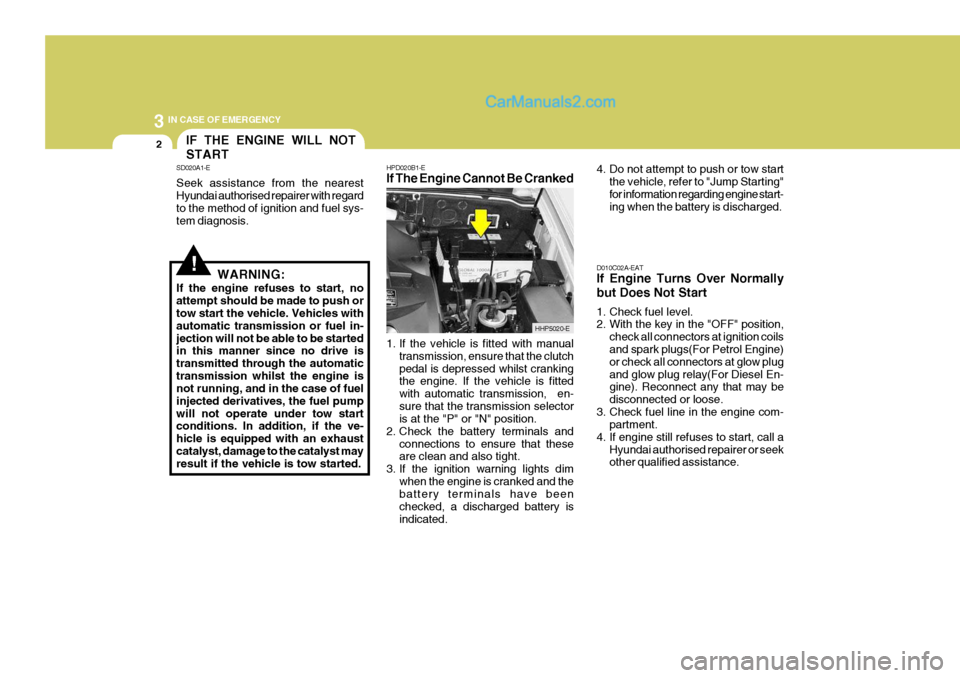
1. If the vehicle is fitted with manual
transmission, ensure that the clutch pedal is depressed whilst cranking the engine. If the vehicle is fitted with automatic transmission, en-sure that the transmission selector is at the "P" or "N" position.
2. Check the battery terminals and
connections to ensure that theseare clean and also tight.
3. If the ignition warning lights dim
when the engine is cranked and thebattery terminals have been checked, a discharged battery isindicated. 4. Do not attempt to push or tow start
the vehicle, refer to "Jump Starting"for information regarding engine start- ing when the battery is discharged.
D010C02A-EAT If Engine Turns Over Normally but Does Not Start
1. Check fuel level.
2. With the key in the "OFF" position, check all connectors at ignition coilsand spark plugs(For Petrol Engine) or check all connectors at glow plugand glow plug relay(For Diesel En- gine). Reconnect any that may be disconnected or loose.
3. Check fuel line in the engine com- partment.
4. If engine still refuses to start, call a Hyundai authorised repairer or seek other qualified assistance.
IF THE ENGINE WILL NOT START
SD020A1-E Seek assistance from the nearest Hyundai authorised repairer with regard to the method of ignition and fuel sys- tem diagnosis.
HHP5020-E
Page 450 of 539
3 IN CASE OF EMERGENCY
4
!
1. Ensure that the booster battery is 12
volt type. If the booster battery is installed in another vehicle, ensure that the two vehicles are not touch- ing.
2. Turn off all unnecessary electrical equipment in both vehicles.
3. Ensure that the engine of the ve- hicle providing the jump start is run- ning prior to connection of the jump cables.
4. Connect the red jump cable to the positive (+) terminal of the boosterbattery and the other end to thepositive (+) terminal of the dis- charged battery.
5. Attach the black jump cable to the negative (-) terminal of the boosterbattery, and the other end to a ground point within the engine compartmentof the vehicle with the flat bat-tery. Do not connect to the negative bat- tery terminal of the flat battery sincesparks may be generated with the subsequent risk of explosion.
6. Raise the booster vehicle engine speed to 2,000 r.p.m. and start theengine of the vehicle with the flat battery. 7. Switch "ON" the main beam
headlamps before carefully remov-ing the jumper cables in the reverse order of attachment. Once the jumper cables have been removed,switch "OFF" the main beam headlamps.
CAUTION:
If the jump cables are incorrectly installed, damage to the vehicle elec- trical system may occur, in particu- lar the electronic components suchas the Fuel Injection system com- puter and the Automatic transmis- sion computer. The battery mustnever be disconnected whilst the engine is running.
IF THE ENGINE OVERHEATS
HPD040A2-E If the temperature gauge indicates overheating:
1. Pull off the road and stop as soon as it is safe to do so.
2. Place the gear selector lever in "P"
(automatic), or neutral (manual trans- mission) and set the parking brake. If the air conditioning is on, turn it off.
3. If coolant is running out under the car or steam is coming out from underthe bonnet, stop the engine. Do not open the bonnet until the coolant hasstopped running or the steaming has stopped. If there is no visible loss of coolant and no steam, leave theengine running and check to be sure the engine cooling fan is operating. If the fan is not running, turn theengine off.
4. Check to see if the water pump drive
belt is broken. If it is not missing,check to see that it is tight. If the drive belt seems to be satisfactory, check for coolant leaking from theradiator, hoses or under the car. (If the air conditioning had been in use, it is normal for cold water to bedraining from it).
Page 464 of 539
44APPEARANCE CARE
2
ZE020B1-E Underbody Coatings Every Hyundai passenger car receives a full underbody and cavity injectiontreatment during production. In order that this treatment may retain maxi- mum effectiveness, it is recommendedthat the underbody receives a power wash and a thorough inspection after each winter season. In doing so anyaccumulations of mud, which act as moisture traps and combine with road salts to accelerate corrosion, will beremoved. Should any damage to or deterioration of the underbody coating be apparent, the advice of a Hyundaiauthorised repairer regarding the use of a compatible repair material should be sought.NOTE: The underbody should never be steam cleaned since the underbody coating may be removed by thisprocess. During the interim period between power washing the underbody, themore vulnerable areas such as wheelarches should be hosed off, particularly during the winter sea-son to prevent prolonged contact of road salt with the body. Ensure that the various drain pointslocated at bottom of the door pan- els are kept clear, to prevent water becoming trapped within the cavi-ties. Wherever possible, the park- ing of the vehicle in a confined, poorly ventilated location (e.g.)garage should be avoided when the vehicle is wet or covered with snow or ice. Under these conditions, theinternal cavities of the vehicle will remain damp for long periods of time which encourage corrosion.Parking the vehicle where good ventilation exists is preferable.APPEARANCE CARE
ZE020A1-E In using the most advanced design and construction practices, every Hyundai is built to retain its original factory finish for many years. How-ever, long term durability is also greatly dependant upon maintaining the vari- ous protection systems and coatingsused in manufacture since constant exposure to the elements will eventu- ally result in their breakdown and lossof effectiveness. The following sug- gestions are made to assist in the maintenance of the vehicle bodywork.
Page 470 of 539
5VEHICLE MAINTENANCE REQUIREMENTS
2
NOTE:The inspection and testing of cer-
tain electronic fuel injection/engine management and automatic trans- mission control systems requirespecialised electronic equipment specifically designed for Hyundai vehicles. The use of general pur-pose electrical test equipment may result in damage to the control unit microprocessors.
DF020C2-E
Specified Scheduled Procedures
The specified scheduled procedures
are listed in the maintenance chartsbeginning at page 5-3. The operationsspecified must be performed at the time or mileage intervals shown irre- spective of whether the mileage inter-val has been reached before the speci- fied time interval.
Certain lubricants and components
degrade with both time and mileage(eg, engine oil and brake fluid) and therefore it is not permissable to basethe maintenance schedule upon mile- age alone. DF020F1-E
SERVICE HISTORY
It is important that all scheduled main-
tenance services are recorded in the warranty and service passport to en- sure that proof of maintenance is avail- able when warranty service is required. It is strongly recommended that the
maintenance operations are performedby a Hyundai authorised repairer be- cause of the need for specialised knowl- edge and tooling and to ensure that nopossibility of invalidating the manufac- turers warranty exists.
The maintenance schedules relate to
vehicles operated under normal condi-tions, vehicles which are operated under adverse conditions will requiremore frequent maintenance which is described at page 5-6. NOTE:
Service schedules may change de-
pending on individual country needs. Please ask your local Hyundai authorised repairer for a copy of the service schedule thatrelates to that country.MAINTENANCE AND SER- VICING REQUIREMENTS
DF020A1-E To ensure the continued reliability and safety of the vehicle, certain routine maintenance operations are requiredat specific mileage or time intervals.It is the responsibility of the vehicleowner to ensure that the maintenanceschedules shown in both this Owner's Manual and the Warranty and Service Passport are adhered to.The new vehicle warranty may beinvalidated if the routine maintenanceoperations are not performed in line with the recommendations outlined and the safety and durability of the vehicleadversely affected.It is recommended that all mainte-nance operations with the exception ofthe daily operating checks are en- trusted to a Hyundai authorised re- pairer to ensure that the latest repairand maintenance procedures and spe- cialized servicing tools are employed. In addition, the use of genuine Hyundaireplacement parts will ensure that the vehicle safety and performance will not be compromised.
Page 471 of 539

5
VEHICLE MAINTENANCE REQUIREMENTS
3
NO. 1 2 3 4 5 6 7 8 DESCRIPTION
ENGINE CONTROL SYSTEM MAINTENANCE (PETROL) ENGINE OIL & FILTER DRIVE BELT (ALT, DAMPER, TENSIONER, IDLER) FUEL FILTER (MPI TYPE) FLUID LEAKS TIMING BELT VENTILATION HOSES AIR CLEANER FILTER SPARK PLUGS (PLATINUM COATED)
F030B02HP-EAT R :Replace I : Inspect and, after Inspection, clean, adjust, repair or replace if necessary.
60 72
R I II
R R
5060
R
I
R
I
4048
R I
R I
R
3036
R
II I I
2024
R I I
R
10 12
R
I I
MILES X 1000 MONTHS
REGULAR SERVICING
YF010A2-E In order to ensure continued reliability, safety and longevity, regular maintenance performed at the intervals specified is
essential. The maintenance intervals specified are based both on time elapsed and mileage covered since the previous maintenance service was performed. However, under severe operating conditions, certain scheduled operations should beperformed at shorter intervals.
Regular maintenance should be entrusted to a Hyundai authorised repairer who is best able to provide the expertise required
to ensure optimum operational performance. In addition the use of Hyundai replacement parts and service consumables will ensure that the original build quality,
operational performance and safety are maintained.
Page 473 of 539
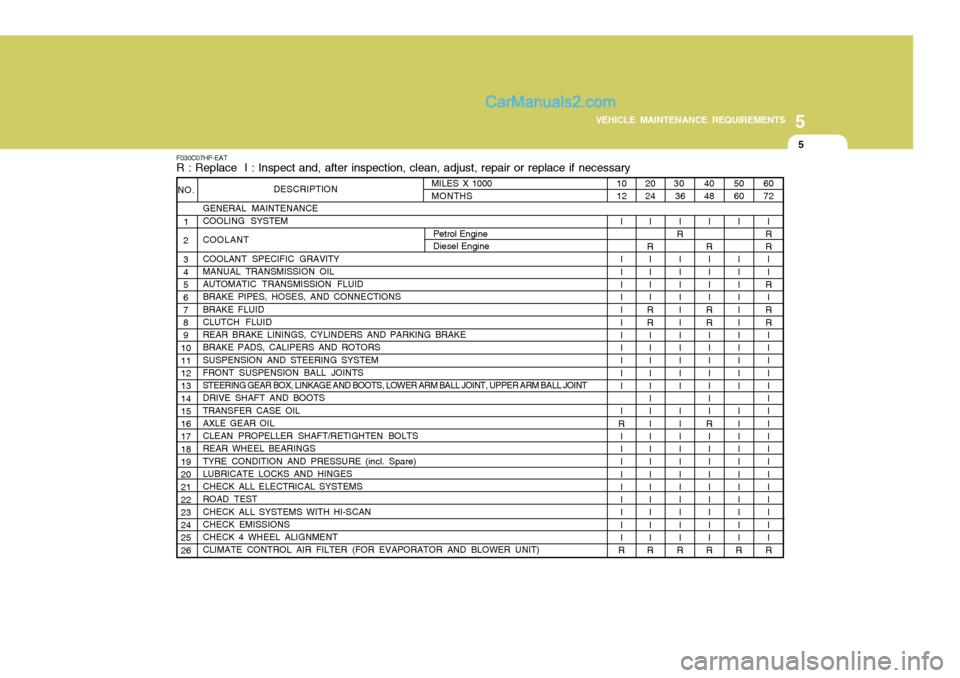
5
VEHICLE MAINTENANCE REQUIREMENTS
5
20 24
I
R II I I
RR II I I I I I I I I I I I I I I I
R
F030C07HP-EAT R : Replace I : Inspect and, after inspection, clean, adjust, repair or replace if necessary
DESCRIPTION
GENERAL MAINTENANCE COOLING SYSTEM COOLANT COOLANT SPECIFIC GRAVITY MANUAL TRANSMISSION OIL AUTOMATIC TRANSMISSION FLUID BRAKE PIPES, HOSES, AND CONNECTIONS BRAKE FLUID CLUTCH FLUID
REAR BRAKE LININGS, CYLINDERS AND PARKING BRAKE BRAKE PADS, CALIPERS AND ROTORS SUSPENSION AND STEERING SYSTEM FRONT SUSPENSION BALL JOINTS
STEERING GEAR BOX, LINKAGE AND BOOTS, LOWER ARM BALL JOINT, UPPER ARM BALL JOINT
DRIVE SHAFT AND BOOTS TRANSFER CASE OIL AXLE GEAR OIL CLEAN PROPELLER SHAFT/RETIGHTEN BOLTS REAR WHEEL BEARINGS TYRE CONDITION AND PRESSURE (incl. Spare) LUBRICATE LOCKS AND HINGES CHECK ALL ELECTRICAL SYSTEMS ROAD TEST CHECK ALL SYSTEMS WITH HI-SCAN CHECK EMISSIONS CHECK 4 WHEEL ALIGNMENT CLIMATE CONTROL AIR FILTER (FOR EVAPORATOR AND BLOWER UNIT)
NO.
1
2 3 4 5 6 7 8 9
1011 12 13 14 15 16 17 18 19 20 21 22 23 24 25 26
60 72
I
RR II
R
I
RR II I I I I I I I I I I I I I I I
R
50 60
I I I I I I I I I I I I I I I I I I I I I I I
R
40 48
I
R II I I
RR II I I I I I
R I I I I I I I I I
R
30
36
I
R
I I I I I I I I I I I I I I I I I I I I I I
R
10 12
I I I I I I I I I I I I I
R I I I I I I I I I
R
MILES X 1000MONTHS
Petrol Engine Diesel Engine
Page 474 of 539

5VEHICLE MAINTENANCE REQUIREMENTS
6
R R RRII II
R RR I
R
ENGINE OIL AND FILTER AIR CLEANER FILTER SPARK PLUGS (FOR PETROL ENGINE) TIMING BELTBRAKE PADS, CALIPERS AND ROTORSREAR BRAKE LININGS, CYLINDERS AND PARKING BRAKESTEERING GEAR BOX, LINKAGE AND BOOTS/LOWER ARM BALL JOINT, UPPER ARM BALL JOINT DRIVE SHAFTS AND BOOTS MANUAL TRANSMISSION OILAUTOMATIC TRANSMISSION FLUIDTRANSFER CASE OIL *1AXLE GEAR OIL *1
CLIMATE CONTROL AIR FILTER
(FOR EVAPORATOR AND BLOWER UNIT)MAINTENANCE UNDER SEVERE USAGE CONDITIONS
A, B, C, D, E, F, G, H, I, K A, B, F, G, H, I, JC, EG, H, I, JD, E, F, GC, D, E, G, H, I C, D, E, G, H, I C, D, E, F C, D, E, F A, C, D, E, F, G, H, I, JA, C, E, F, G, H, IC, E, G, H, IC, E, G, H, I C, E
F040A07HP-EAT The following items must be serviced more frequently on cars normally used under severe driving conditions. Refer to the chart below for the appropriate maintenance intervals. R : Replace I : Inspect and, after inspection, clean, adjust, repair or replace if necessary
EVERY 4,500 MILES OR 6 MONTHS MORE FREQUENTLY MORE FREQUENTLYEVERY 37,000 MILES OR 48 MONTHSMORE FREQUENTLYMORE FREQUENTLY MORE FREQUENTLYEVERY 9,000 MILES OR 12 MONTHS EVERY 60,000 MILESEVERY 27,000 MILESEVERY 60,000 MILESMORE FREQUENTLYMORE FREQUENTLY
DRIVING
CONDITION
MAINTENANCE INTERVALS
MAINTENANCE
OPERATION
MAINTENANCE ITEM
*1. Transfer Case Oil and Axle Gear Oil should be checked(and replaced if necessary) anytime they have been submerged in water over 15.7 in. (40 cm) deep.
PETROL ENGINE DIESEL ENGINE
SEVERE DRIVING CONDITIONS A - Repeatedly driving short distance of less than 5miles(8km) in normal temperature or less than 10miles(16km) in freezing temperature
B - Extensive engine idling or low speed driving for long distances
C - Driving on rough, dusty, muddy, unpaved, graveled or salt- spread roads
D - Driving in areas using salt or other corrosive materials or in very cold weather E - Driving in sandy areas
F - Driving in heavy traffic area over 90°F(32°C) G - Driving on uphill, downhill, or mountain roadH - Towing a Trailer, or using a camper, or roof rack
I - Driving as a patrol car, taxi, other commercial use or vehicle towing
J - Driving over 100 MPH(170 Km/h)K - Frequently driving in stop-and-go conditions
Page 478 of 539
5VEHICLE MAINTENANCE REQUIREMENTS
10
F070J01A-AAT
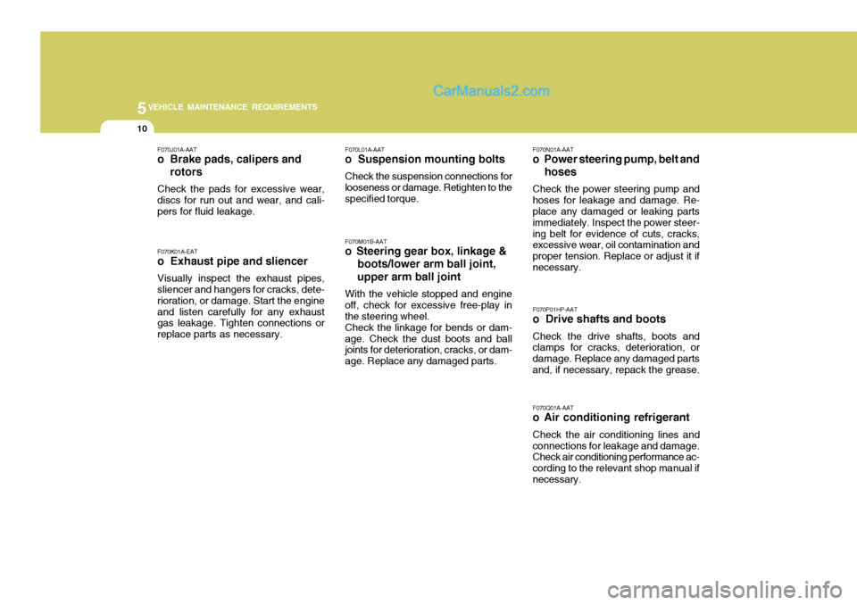
o Brake pads, calipers and rotors
Check the pads for excessive wear, discs for run out and wear, and cali- pers for fluid leakage. F070K01A-EAT o Exhaust pipe and sliencer Visually inspect the exhaust pipes, sliencer and hangers for cracks, dete- rioration, or damage. Start the engineand listen carefully for any exhaust gas leakage. Tighten connections or replace parts as necessary. F070L01A-AAT
o Suspension mounting bolts
Check the suspension connections for
looseness or damage. Retighten to the specified torque.
F070M01B-AAT
o Steering gear box, linkage & boots/lower arm ball joint, upper arm ball joint
With the vehicle stopped and engine
off, check for excessive free-play in the steering wheel. Check the linkage for bends or dam-
age. Check the dust boots and ball joints for deterioration, cracks, or dam- age. Replace any damaged parts. F070N01A-AAT
o Power steering pump, belt and hoses
Check the power steering pump and
hoses for leakage and damage. Re- place any damaged or leaking parts immediately. Inspect the power steer-ing belt for evidence of cuts, cracks, excessive wear, oil contamination and proper tension. Replace or adjust it ifnecessary.
F070P01HP-AAT
o Drive shafts and boots
Check the drive shafts, boots and
clamps for cracks, deterioration, ordamage. Replace any damaged partsand, if necessary, repack the grease.
F070Q01A-AAT
o Air conditioning refrigerant
Check the air conditioning lines and
connections for leakage and damage. Check air conditioning performance ac- cording to the relevant shop manual ifnecessary.