Page 380 of 539
1CONTROLS AND EQUIPMENT
72
Push in the map light switch to turn the light on or off. This light produces a spot beam for convenient use as a map light at night or as a personal lightfor the driver and the passenger.INTERIOR LIGHT
B480B01Y-AAT Map Light
B480B01HP
!
B460D01HP-EAT Manual Operation of Sunroof If the sunroof fails to operate:
1. Remove the round plug in the front
of the roof panel with a flat-bladed screwdriver or coin. 2. Insert the hexagonal head wrench
provided with the vehicle into the socket. This wrench can be found in the glove box or the tool bag.
3. Turn the wrench clockwise to open
or counterclockwise to close.
CAUTION:
Remove the round plug with the groove pointing to the front and the rear. Otherwise, the projections ofthe plug may break if it is not posi- tioned properly.
HHP2021
HHP2022
Page 416 of 539

1CONTROLS AND EQUIPMENT
108
!
B880C02B-EAT Glass Antenna (Not all models) When the radio power switch is turned on whilst the ignition key is in either the "ON" or "ACC" position, your car will receive both AM and FM broadcastsignals through the antenna in the rear quarter glass. CAUTION:
o Do not clean the inner side of the rear quarter glass with an abra- sive type of glass cleaner or usea scraper to remove foreign de- posits from the inner surface of the glass as this may cause dam-age to the antenna elements.
o Avoid adding metallic coating
such as Ni, Cd, and so on. Thesecan disturb receiving AM and FM broadcast signals.
HHP2184-D
ANTENNA
!
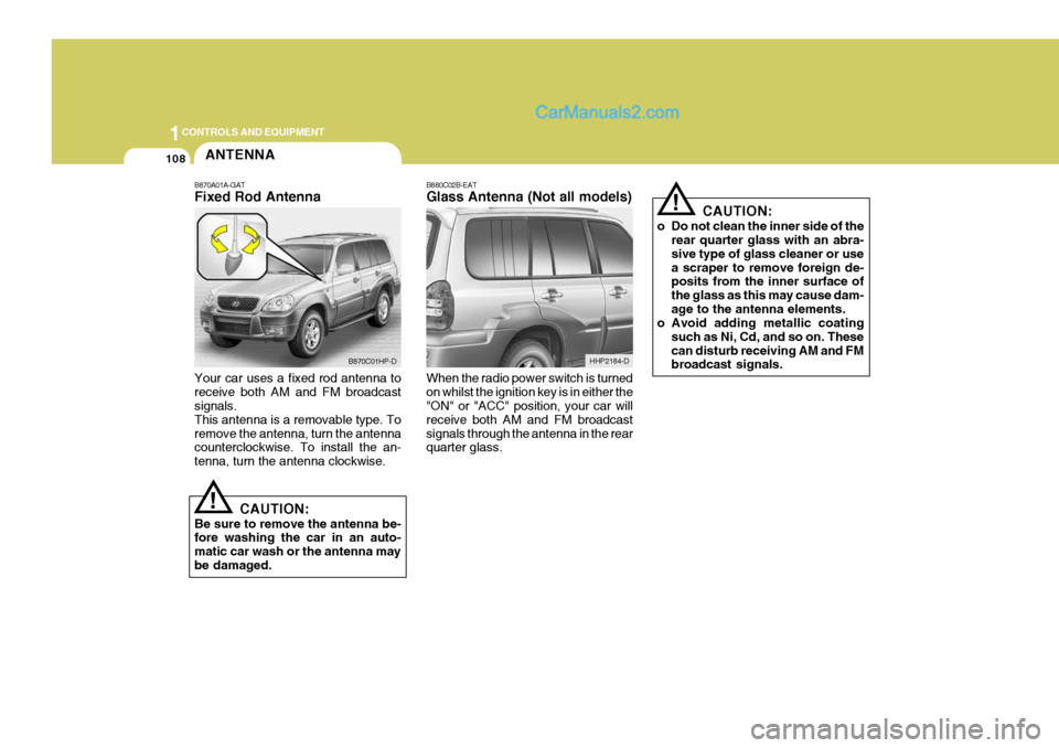
B870A01A-GAT Fixed Rod Antenna Your car uses a fixed rod antenna to receive both AM and FM broadcast signals. This antenna is a removable type. Toremove the antenna, turn the antenna counterclockwise. To install the an- tenna, turn the antenna clockwise.
CAUTION:
Be sure to remove the antenna be- fore washing the car in an auto- matic car wash or the antenna maybe damaged.
B870C01HP-D
Page 421 of 539

2
DRIVING YOUR HYUNDAI
5
!
YC030A2-E STEERING WHEEL LOCK When the ignition key is removed, the steering wheel lock will be activated.The lock only engages at one position of the steering wheel and therefore it will be necessary to turn the wheel untilthis position is reached. It is not, how- ever, necessary for the lock to be en- gaged before leaving the vehicle sincein the event of attempted unauthorised removal, the lock will engage when attempts are made to steer the vehicle.
CAUTION:
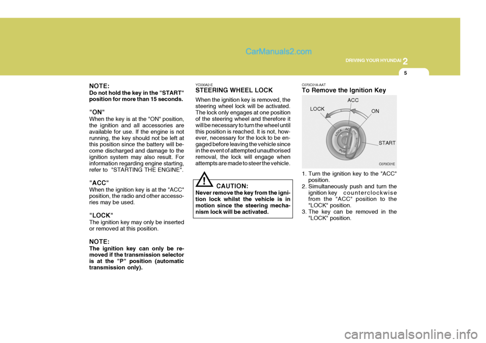
Never remove the key from the igni-tion lock whilst the vehicle is inmotion since the steering mecha- nism lock will be activated. C070C01A-AAT To Remove the Ignition Key
1. Turn the ignition key to the "ACC"
position.
2. Simultaneously push and turn the
ignition key counterclockwise
from the "ACC" position to the "LOCK" position.
3. The key can be removed in the "LOCK" position.
LOCK
C070C01E
ACC
ON
START
NOTE: Do not hold the key in the "START" position for more than 15 seconds. "ON" When the key is at the "ON" position, the ignition and all accessories are available for use. If the engine is notrunning, the key should not be left at this position since the battery will be- come discharged and damage to theignition system may also result. For information regarding engine starting, refer to "STARTING THE ENGINE". "ACC" When the ignition key is at the "ACC" position, the radio and other accesso- ries may be used. "LOCK" The ignition key may only be inserted or removed at this position. NOTE: The ignition key can only be re- moved if the transmission selector is at the "P" position (automatictransmission only).
Page 452 of 539
3 IN CASE OF EMERGENCY
6
D040B03HP-EAT Handling the Spare Tyre
1. Obtain the spare wheel rod (Jackhandle) after folding up the seat cushion of the rear seat . To fold up the seat cushion, refer to the page 1-23. 2. Insert the spare wheel rod into the
hole in the upper pad of the rear bumper.
3. Connect the wheel nut wrench to the spare wheel rod.
4. Turn the wheel nut wrench counter-
clockwise and the spare tyre will lower.
Tyre Size Inflation Pressure
FULL Size 29 psi (200 kPa)SPARE TYRE
YD050A1-E For Full Size The following instructions for the FULL SIZE spare tyre should be observed:Check inflation pressure as soon as possible after installing the spare tyre, and adjust to the specified pressure.The tyre pressure should be periodi- cally checked and maintained at the specified pressure whilst the tyre isstored. Spare Tyre Pressure
HHP4015
HHP4025
Page 453 of 539

3
IN CASE OF EMERGENCY
7
!
5. Remove the lift plate from the centre
of the spare tyre after the spare tyre is lowered completely.
Installation is the reverse order of re-moval.
CAUTION:
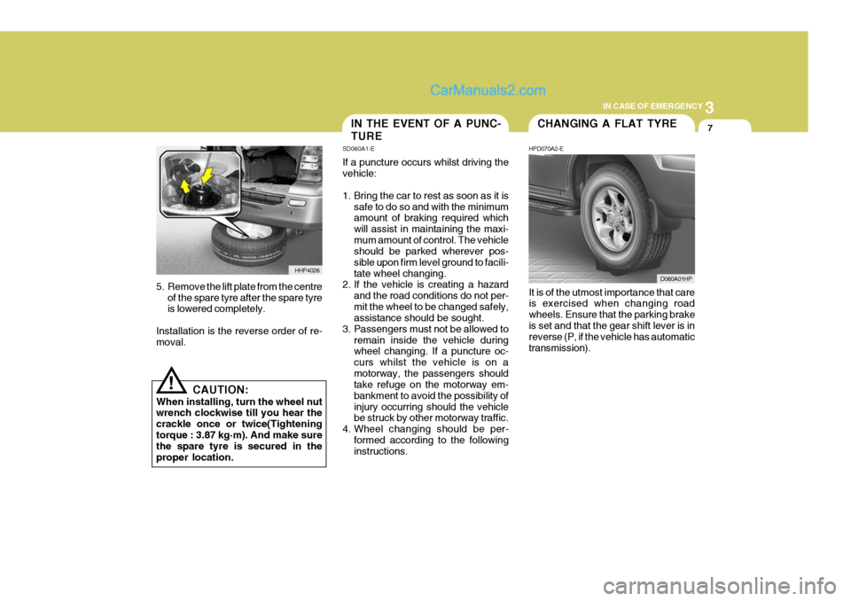
When installing, turn the wheel nutwrench clockwise till you hear the crackle once or twice(Tighteningtorque : 3.87 kg·m). And make sure the spare tyre is secured in the proper location. It is of the utmost importance that care is exercised when changing road wheels. Ensure that the parking brakeis set and that the gear shift lever is in reverse (P, if the vehicle has automatic transmission).
HHP4026
IN THE EVENT OF A PUNC- TURE
SD060A1-E If a puncture occurs whilst driving the vehicle:
1. Bring the car to rest as soon as it is
safe to do so and with the minimum amount of braking required which will assist in maintaining the maxi-mum amount of control. The vehicle should be parked wherever pos- sible upon firm level ground to facili-tate wheel changing.
2. If the vehicle is creating a hazard
and the road conditions do not per-mit the wheel to be changed safely, assistance should be sought.
3. Passengers must not be allowed to remain inside the vehicle duringwheel changing. If a puncture oc- curs whilst the vehicle is on amotorway, the passengers should take refuge on the motorway em- bankment to avoid the possibility ofinjury occurring should the vehicle be struck by other motorway traffic.
4. Wheel changing should be per- formed according to the followinginstructions.CHANGING A FLAT TYRE
HPD070A2-E
D060A01HP
Page 455 of 539
3
IN CASE OF EMERGENCY
9
ZD070D1-E 2. Block the Wheel Block the wheel that is diagonally op- posite from the flat tyre to prevent thevehicle from rolling when the car is raised on the jack.
Flat tyre HHP4022D065C02HP-GAT
3. Removing the Spare Wheel Cap Pry off the wheel cap, using the bar as shown in the illustration.
o Alloy Wheel Cap type
HHP4027 ZD070F1-E 4. Loosen Wheel Nuts The wheel nuts should be loosened slightly before raising the car. To loosenthe nuts, turn the wheel nut wrench counterclockwise. When doing this, be sure that the socket is seated com-pletely over the nut so it cannot slip off. For maximum leverage, position the wheel nut wrench so the handle is to theright as shown in the drawing. Then, whilst holding the wheel nut wrench near the end of the handle, pull up on itwith steady pressure. Do not remove the nuts at this time. Just loosen them about one-half turn.
HHP4028
Page 456 of 539
3 IN CASE OF EMERGENCY
10
D060F02HP-EAT 6. Raising the Car
o Open the lid at the left corner of theluggage compartment.
o Loosen the hexagonal bolt, and then take out the jack. Using the jack handle, turn the release valve clockwise until it reaches a stop.
Then fit the jack handle into the holder, and align the groove of the jack handlewith the notch of the holder.
D060E01A-AAT 5. Put the Jack in Place The base of the jack should be placed on firm, level ground. The jack should be positioned as shown in the illustra- tion.
Front
HHP4023
HHP4024
Rear
D060F01HP
HHP4016
HHP4017
Page 457 of 539

3
IN CASE OF EMERGENCY
11
Move the jack handle up and down to raise the ram until just before the jack contacts the jacking point of the car. Position the jack with the jack handle.Position it only at the specified points indicated in the "Put the Jack in Place". Use of the jack at other points coulddamage the car. Moving the jack handle up and down to raise the ram.
HHP4018 As the jack begins to raise the vehicle, double check that it is properly posi-tioned and will not slip. Raise the car high enough so that the fully inflated spare tyre can be installed.To do this, you will need more ground clearance than is required to remove the flat tire. Using the jack handle, turn the release valve counterclockwise slow to lowerthe ram, and then take out the jack. When the release valve is difficult to turn by jack handle, connect the wheelnut wrench to the jack handle.
HHP4020
Stop mark
HHP4019
!CAUTION:
(1) Use only the jack included with the vehicle and use it only for changing a wheel and for install- ing tyre chains.
(2) Position the jack on a hard, level surface.
(3) If the release valve is loosened by turning it 2 or more times in the counterclockwise direction, the jack's oil will leak and the jackcannot be used.