2006 Hyundai Terracan clock
[x] Cancel search: clockPage 240 of 539
6
DO-IT-YOURSELF MAINTENANCE
13
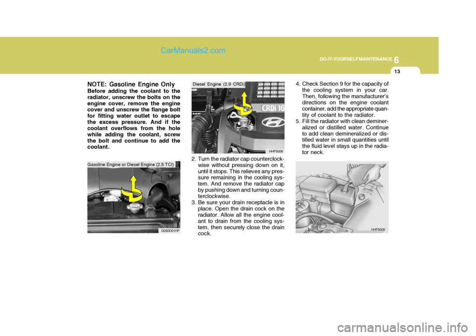
NOTE: Gasoline Engine Only Before adding the coolant to the radiator, unscrew the bolts on theengine cover, remove the engine cover and unscrew the flange bolt for fitting water outlet to escapethe excess pressure. And if the coolant overflows from the hole while adding the coolant, screwthe bolt and continue to add the coolant.
G050D01HP 2. Turn the radiator cap counterclock-
wise without pressing down on it, until it stops. This relieves any pres- sure remaining in the cooling sys- tem. And remove the radiator capby pushing down and turning coun- terclockwise.
3. Be sure your drain receptacle is in place. Open the drain cock on theradiator. Allow all the engine cool- ant to drain from the cooling sys-tem, then securely close the drain cock. HHP5006
Gasoline Engine or Diesel Engine (2.5 TCI) Diesel Engine (2.9 CRDi)
Gasoline Engine or Diesel Engine (2.5 TCI)
4. Check Section 9 for the capacity of
the cooling system in your car. Then, following the manufacturer’s directions on the engine coolant container, add the appropriate quan-tity of coolant to the radiator.
5. Fill the radiator with clean deminer-
alized or distilled water. Continueto add clean demineralized or dis- tilled water in small quantities until the fluid level stays up in the radia-tor neck.
HHP5008
Page 258 of 539
6
DO-IT-YOURSELF MAINTENANCE
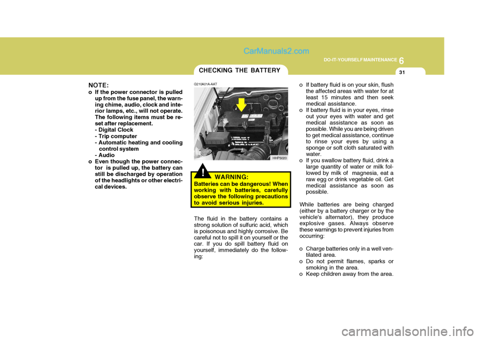
31CHECKING THE BATTERY
!
G210A01A-AAT
WARNING:
Batteries can be dangerous! When
working with batteries, carefully observe the following precautionsto avoid serious injuries. o If battery fluid is on your skin, flush
the affected areas with water for atleast 15 minutes and then seek medical assistance.
o If battery fluid is in your eyes, rinse out your eyes with water and getmedical assistance as soon as possible. While you are being drivento get medical assistance, continue to rinse your eyes by using a sponge or soft cloth saturated withwater.
o If you swallow battery fluid, drink a large quantity of water or milk fol- lowed by milk of magnesia, eat a raw egg or drink vegetable oil. Getmedical assistance as soon as possible.
While batteries are being charged (either by a battery charger or by thevehicle's alternator), they produce explosive gases. Always observe these warnings to prevent injuries fromoccurring:
o Charge batteries only in a well ven- tilated area.
o Do not permit flames, sparks or smoking in the area.
o Keep children away from the area.
The fluid in the battery contains a
strong solution of sulfuric acid, whichis poisonous and highly corrosive. Becareful not to spill it on yourself or the car. If you do spill battery fluid on yourself, immediately do the follow-ing: HHP5020
NOTE:
o If the power connector is pulled up from the fuse panel, the warn-ing chime, audio, clock and inte- rior lamps, etc., will not operate. The following items must be re-set after replacement.- Digital Clock - Trip computer
- Automatic heating and cooling
control system
- Audio
o Even though the power connec- tor is pulled up, the battery can still be discharged by operation of the headlights or other electri-cal devices.
Page 265 of 539

6 DO-IT-YOURSELF MAINTENANCE
38REPLACING HEADLIGHT BULBS
G260A03A-GAT Before attempting to replace a head- light bulb, be sure the switch is turned to the "OFF" position. The next paragraph shows how to reach the headlight bulbs so they may be changed. Be sure to replacethe burned-out bulb with one of the same number and wattage rating.
CAUTION:
o Keep the lamps out of contact with petroleum product, such as oil, gasoline, etc.
o After heavy, driving rain or wash- ing, headlight and taillight lensescould appear frosty. This condi- tion is caused by the temperature difference between the lamp in-side and outside. This is similar to the condensation on your win- dows inside your vehicle duringthe rain and doesn’t indicate a problem with your vehicle. If the water leaks into the lamp bulbcircuitry, have the vehicle checked by an Authorized Hyundai Dealer.
! G270A01B-GAT
Headlight Bulb
1. Allow the bulb to cool. Wear eye
protection.
2. Open the engine hood.
3. Always grasp the bulb by its plas- tic base, avoid touching the glass.
4. Using a spanner, remove the head- light assembly mounting bolts.
5. Disconnect the power cord from the bulb base in the back of the headlight.
G270A01HP7. Disconnect the connector from the
bulb base in the back of the head- light.
G270A02HP
6. Turn the plastic cover counterclock- wise and remove it. 8. Push the bulb spring to remove the
headlight bulb.
Page 293 of 539
10INDEX
2
A Air bag ....................................................................... 1-47
Air Cleaner Filter ........................................................ 6-14
Air Conditioning Care ........................................................................ 6-23
Filter ............................................................ 1-118, 6-24
Operation ..................................................... 1-110, 6-23
Switch ................................................................... 1-110
Antenna ................................................................... 1-140
Ashtray ...................................................................... 1-81
Audio Fault Code ..................................................... 1-137
Automatic Heating and Cooling Control System ...... 1-112
B Battery .............................................................. 2-26, 6-31
Bi-Level Heating ...................................................... 1-108
Brake
Anti-lock brake system (ABS) ................................ 2-21
Checking the brakes ............................................... 6-21
Fluid ........................................................................ 6-21
Pedal clearance ...................................................... 6-27
Pedal free-play ........................................................ 6-26
Practices ................................................................ 2-22
Breaking-In your New Hyundai .................................... 1-3 C
Care of Cassette Tapes ....................
..................... 1-139
Care of Discs .......................................................... 1-138
Cargo Security Screen .............................................. 1-93
Cassette Tape Player Operation (H240) .................. 1-124
Cassette Tape Player Operation (H280) .................. 1-129
Catalytic Converter ...................................................... 7-3
CD Auto changer (H280) ................................. 1-92, 1-134
Center Console Compartment ....................................1-87
Center console armrest .......................................... 1-87
Center console box ................................................. 1-87
Child Restraint System .............................................. 1-39
Child-Protector Rear Door Lock ................................. 1-12
Cigarette Lighter ........................................................ 1-79
Clock ......................................................................... 1-78
Clutch Checking fluid ......................................................... 6-22
Pedal free-play ........................................................ 6-26
Combination Light
Daytime running lights ............................................ 1-74
Headlight flasher ..................................................... 1-75
Headlight swi tch ..................................................... 1-73
High-beam switch ................................................... 1-74
Lane change si gnal ................................................. 1-73
Parking light auto cut ............................................. 1-74
Turn signal operation .............................................. 1-73
Compact Disc Player Operation (H280) ................... 1-131
Cooling Fans ............................................................. 6-33
Page 295 of 539

10INDEX
4
G General Checks .......................................................... 6-5
Glove Box ................................................................. 1-86
HHazard Warning System ............................................ 1-77
Headlight Aiming Adjustm ent ..................................... 6-39
Headlight Leveling Device S ystem ............................1-99
Heating and Ventilation ............................................ 1-104
Air flow control ........................................... 1-105, 1-116
Temperature control .... .......................................... 1-107
High-Mounted Rear Stop Light ...................................1-95
Hood Release ............................................................ 1-97
Horn ........................................................................... 1-98
I Ignition Sw itch ............................................................. 2-3
Immobilizer S ystem ..................................................... 1-5
Limp Home Procedures ................................... 1-7, 1-9
Key ................................................................... 1-5, 1-8
Indicator and Warning Lights.................................... 1-58
Instrument Cluster and Indicator Li ghts................... 1-54
Instrument Panel Light Control (Rheo stat)............... 1-79
Interior Light .............................................................. 1-85
Intermittent Wiper ..................................................... 1-77
J Jump Starting .............................................................. 3-3 K
Key .............................................................................. 1-4
If you lose your keys ............................................. 3-17
Positions ................................................................... 2-4
L Limited-Slip D ifferential ............................................. 2-22
Luggage Compartment
Cargo Security Screen ........................................... 1-93
Light ........................................................................ 1-92
Net .......................................................................... 1-93
M Maintenance Intervals Explanation of scheduled maintenance items ......... 5-9
Maintenance under severe usage conditions .......... 5-8 Scheduled maintenance ........................................... 5-4
Service requ irements............................................... 5-2
Mirrors Day/night inside rearview ....... .................................1-90
Outside rearvi ew ..................................................... 1-88
Multimeter .................................................................. 1-69
Altimeter ................................................................. 1-70
Barometer ............................................................... 1-72
Digital Clock ........................................................... 1-72
Electrical azimuth compass ................................... 1-70
Relative altimeter .................................................... 1-71
Page 317 of 539
1
CONTROLS AND EQUIPMENT
9
!WARNING:
o Before you drive away, be sure that all the doors are securely closed. It is also recommendedthat the child-protector rear door locks are in the 'lock' position so that children cannot open therear doors from inside the ve- hicle accidentally.
o Before opening the door, always look for and avoid oncoming traf- fic.
o In case of an accident, the door is unlocked automatically(Not allmodels).
DOOR LOCKS
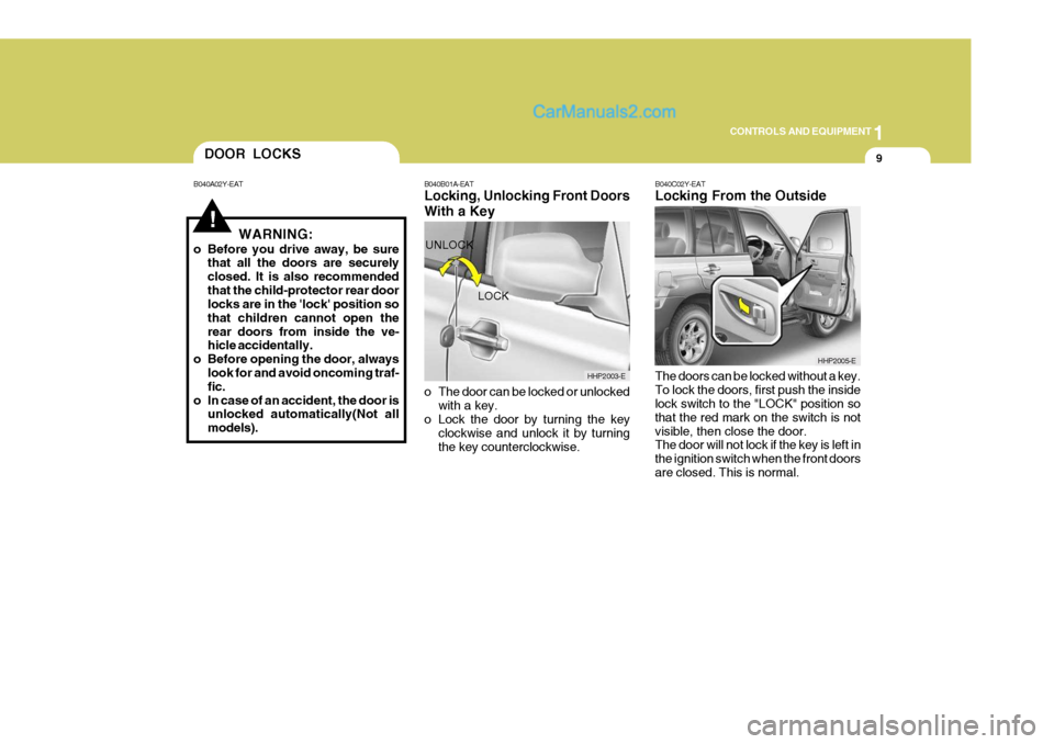
B040A02Y-EAT B040B01A-EAT
Locking, Unlocking Front Doors With a Key
o The door can be locked or unlocked
with a key.
o Lock the door by turning the key
clockwise and unlock it by turning the key counterclockwise. B040C02Y-EAT Locking From the Outside The doors can be locked without a key. To lock the doors, first push the inside lock switch to the "LOCK" position so that the red mark on the switch is notvisible, then close the door. The door will not lock if the key is left in the ignition switch when the front doorsare closed. This is normal.
LOCK
UNLOCK
HHP2003-E
HHP2005-E
Page 327 of 539
1
CONTROLS AND EQUIPMENT
19
!
!
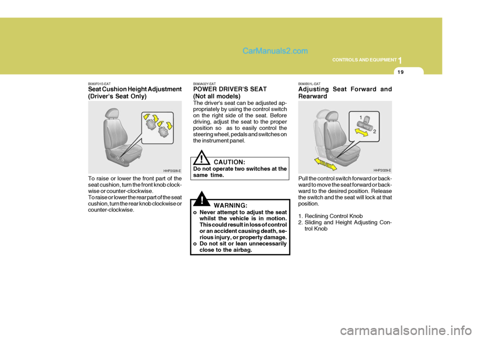
B080F01S-EAT Seat Cushion Height Adjustment (Driver's Seat Only) To raise or lower the front part of the seat cushion, turn the front knob clock- wise or counter-clockwise. To raise or lower the rear part of the seatcushion, turn the rear knob clockwise or counter-clockwise. B090A02Y-EAT POWER DRIVER'S SEAT (Not all models) The driver's seat can be adjusted ap- propriately by using the control switch on the right side of the seat. Beforedriving, adjust the seat to the proper position so as to easily control the steering wheel, pedals and switches onthe instrument panel.
CAUTION:
Do not operate two switches at thesame time.
WARNING:
o Never attempt to adjust the seat whilst the vehicle is in motion.This could result in loss of controlor an accident causing death, se- rious injury, or property damage.
o Do not sit or lean unnecessarily close to the airbag.
HHP2028-E B090B01L-EAT Adjusting Seat Forward and Rearward Pull the control switch forward or back- ward to move the seat forward or back- ward to the desired position. Release the switch and the seat will lock at thatposition.
1. Reclining Control Knob
2. Sliding and Height Adjusting Con-
trol KnobHHP2029-E
2
1
Page 374 of 539
1CONTROLS AND EQUIPMENT
66DIGITAL CLOCK
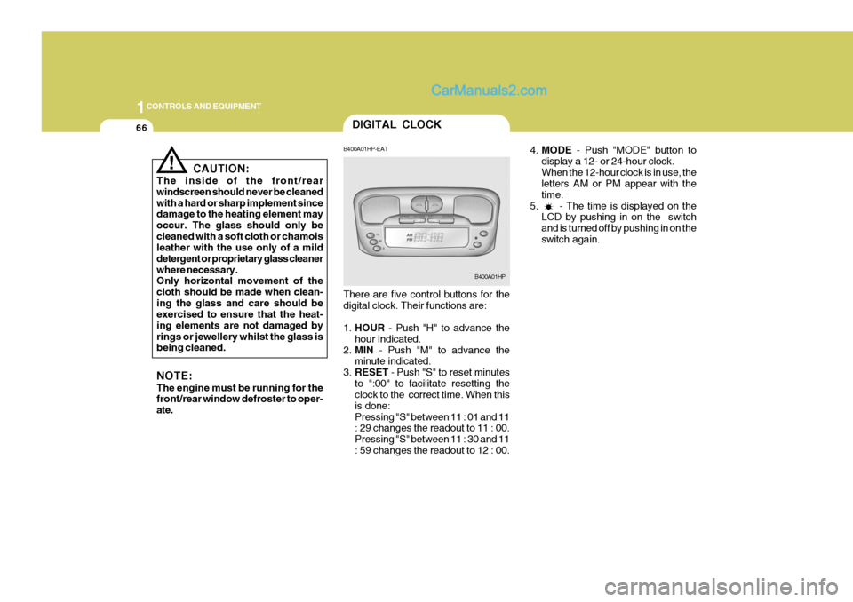
4.MODE - Push "MODE" button to
display a 12- or 24-hour clock. When the 12-hour clock is in use, the letters AM or PM appear with the time.
5. - The time is displayed on the LCD by pushing in on the switchand is turned off by pushing in on theswitch again.
! CAUTION:
The inside of the front/rear windscreen should never be cleanedwith a hard or sharp implement since damage to the heating element may occur. The glass should only becleaned with a soft cloth or chamois leather with the use only of a mild detergent or proprietary glass cleanerwhere necessary. Only horizontal movement of the cloth should be made when clean-ing the glass and care should be exercised to ensure that the heat- ing elements are not damaged byrings or jewellery whilst the glass is being cleaned. NOTE: The engine must be running for the front/rear window defroster to oper- ate. B400A01HP-EAT There are five control buttons for the digital clock. Their functions are: 1.
HOUR - Push "H" to advance the
hour indicated.
2. MIN - Push "M" to advance the
minute indicated.
3. RESET - Push "S" to reset minutes
to ":00" to facilitate resetting the clock to the correct time. When this is done:Pressing "S" between 11 : 01 and 11 : 29 changes the readout to 11 : 00. Pressing "S" between 11 : 30 and 11: 59 changes the readout to 12 : 00.
B400A01HP