2006 Hyundai Terracan light
[x] Cancel search: lightPage 509 of 539

6
OWNER MAINTENANCE
31
!
!
3. Check to be sure that the warning
lamp illuminates when the ignition key is turned to "ON", and that it goes off when the engine is started. If in doubt, consult your nearest Hyundai authorised repairer.
NOTE: It is recommended that water accu- mulated in the fuel filter should be removed by a Hyundai authorised repairer.
WARNING:
Be sure to carefully wipe away anywater drained out in this manner, because the fuel mixed in the water might be ignited and resultin a fire. Before attempting to replace a head-
light bulb, be sure the switch is turned to the "OFF" position.
The next paragraph shows how to
reach the headlight bulbs so they may be changed. Be sure to replacethe burned-out bulb with one of the same number and wattage rating.
Ensure that the replacement bulb has
the same cap configuration and watt-age as the original.
See page 6-35 for the wattage descrip-
tions.
CAUTION:
Keep the lamps out of contact with
petroleum products, such as oil, petrol, etc.
REPLACING HEADLIGHT BULBS
G260A01HP-EAT
G300B02HP-EAT
Removal Of Water From TheFuel Filter (For Diesel Engine)
If the fuel filter warning lamp illumi- nates during driving, it indicates that water has accumulated in the fuel filter. If this occurs, remove the wateras described below.
1. Loosen the drain plug at the bot- tom of the fuel filter.
2. Tighten the drain plug when water no longer comes out.
HHP5047-E
Page 510 of 539
6 OWNER MAINTENANCE
32
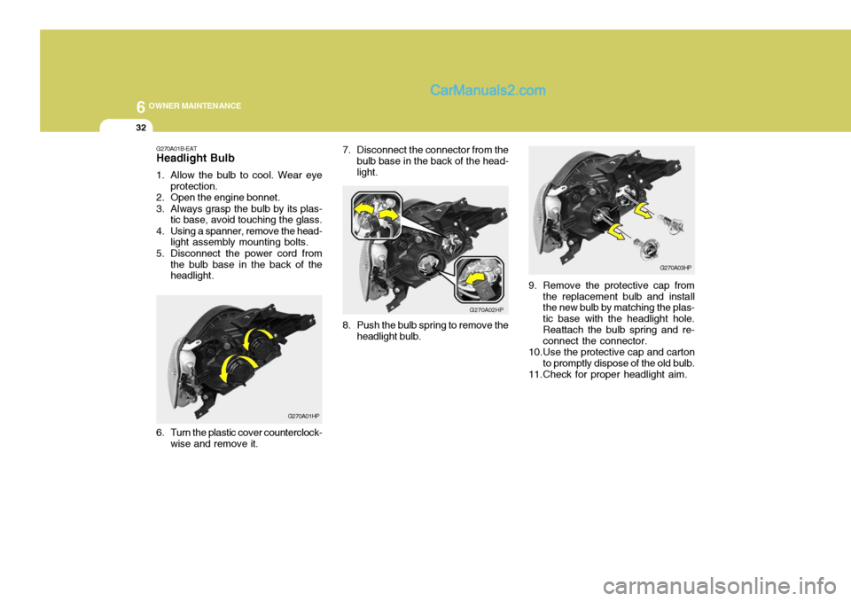
7. Disconnect the connector from the
bulb base in the back of the head- light.
G270A02HP
8. Push the bulb spring to remove the headlight bulb.
G270A03HP
9. Remove the protective cap from the replacement bulb and install the new bulb by matching the plas- tic base with the headlight hole.Reattach the bulb spring and re- connect the connector.
10.Use the protective cap and carton to promptly dispose of the old bulb.
11.Check for proper headlight aim.
G270A01B-EAT
Headlight Bulb
1. Allow the bulb to cool. Wear eye
protection.
2. Open the engine bonnet.
3. Always grasp the bulb by its plas- tic base, avoid touching the glass.
4. Using a spanner, remove the head- light assembly mounting bolts.
5. Disconnect the power cord from the bulb base in the back of the headlight.
G270A01HP
6. Turn the plastic cover counterclock- wise and remove it.
Page 511 of 539
6
OWNER MAINTENANCE
33
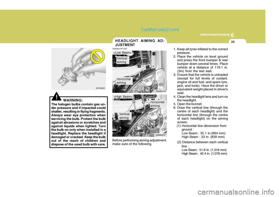
Before performing aiming adjustment, make sure of the following.HEADLIGHT AIMING AD- JUSTMENT
G290A01HP-EAT
1. Keep all tyres inflated to the correct
pressure.
2. Place the vehicle on level ground and press the front bumper & rear bumper down several times. Placevehicle at a distance of 118.1 in. (3m) from the test wall.
3. Ensure that the vehicle is unloaded (except for full levels of coolant, engine oil and fuel, and spare tyre,jack, and tools). Have the driver or equivalent weight placed in driver's seat.
4. Clean the headlight lens and turn on the headlight.
5. Open the bonnet.
6. Draw the vertical line (through the centre of each headlight) and thehorizontal line (through the centre of each headlight) on the aiming screen.
(1) Horizontal line dimension from
Horizontal aiming
Vertical aiming
G290B01HP
G290B02HP
Horizontal aiming
Vertical aiming
ground :Low Beam : 35.1 in.(894 mm) High Beam : 33 in. (839 mm)
(2) Distance between each vertical line :Low Beam : 51.8 in. (1,316 mm) High Beam : 42.4 in. (1,076 mm)
!WARNING:
The halogen bulbs contain gas un-
der pressure and if impacted could shatter, resulting in flying fragments.Always wear eye protection when servicing the bulb. Protect the bulb against abrasions or scratches andagainst liquids when lighted. Turn the bulb on only when installed in a headlight. Replace the headlight ifdamaged or cracked. Keep the bulb out of the reach of children and dispose of the used bulb with care. G270A03O
Page 512 of 539
6 OWNER MAINTENANCE
34
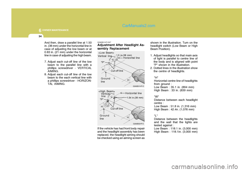
G290B01HP-EAT
Adjustment After Headlight As- sembly Replacement
If the vehicle has had front body repair
and the headlight assembly has been replaced, the headlight aiming should be checked using an aiming screen as shown in the illustration. Turn on theheadlight switch (Low Beam or HighBeam Position).
1. Adjust headlights so that main axis of light is parallel to centre line ofthe body and is aligned with point"P" shown in the illustration.
2. Dotted lines in the illustration show
the centre of headlights.
"H"Horizontal centre line of headlightsfrom ground : Low Beam : 35.1 in. (894 mm) High Beam : 33 in. (839 mm) "W" Distance between each headlight centre :
Low Beam : 51.8 in. (1,316 mm) High Beam : 42.4n. (1,076 mm) "L" Distance between the headlights and the wall that the lights are tested against : Low Beam : 118.1 in. (3,000 mm) High Beam : 118.1in. (3,000 mm)
G290B02HP-E
G290B01HP-D
L
W
Cut-off line
Ground
line "P"
Horizontal line
Vertical line
1.5 in.(38 mm)
H
L
W
Cut-off line
Ground line "P"
Horizontal line
Vertical
0.83 in. (21mm) 1.54 in.(39 mm)
H
H
line
And then, draw a parallel line at 1.50 in. (38 mm) under the horizontal line incase of adjusting the low beam or at 0.83 in. (21 mm) under the horizontal line in case of adjusting the high beam.
7. Adjust each cut-off line of the low
beam to the parallel line with a phillips screwdriver - VERTICAL AIMING.
8. Adjust each cut-off line of the low beam to the each vertical line witha phillips screwdriver - HORIZON-TAL AIMING.
Page 513 of 539
6
OWNER MAINTENANCE
35
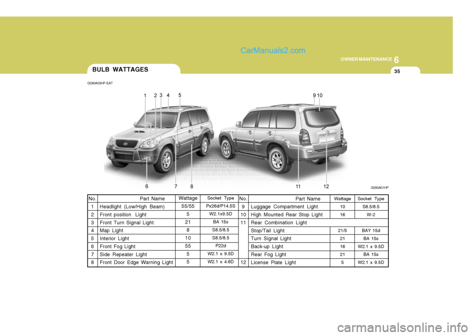
Socket Type
Px26d/P14.5S W2.1x9.5D
BA 15s
S8.5/8.5 S8.5/8.5 P22d
W2.1 x 9.5D W2.1 x 4.6D
Part Name
Headlight (Low/High Beam)Front position Light Front Turn Signal Light Map Light Interior Light Front Fog Light Side Repeater Light Front Door Edge Warning Light Socket Type
S8.5/8.5
W-2
BAY 15d BA 15s
W2.1 x 9.5D BA 15s
W2.1 x 9.5D
No.
9
10 11 12 Part Name
Luggage Compartment Light High Mounted Rear Stop Light Rear Combination Light Stop/Tail Light Turn Signal Light Back-up Light Rear Fog Light License Plate Light
No.
1 2 3 4 5 6 7 8
BULB WATTAGES
G280A01HP
G280A03HP-EAT
Wattage55/55 5
21 8
10 55 55Wattage 10 16
21/5 2116 21
5
Page 518 of 539
6 OWNER MAINTENANCE
40
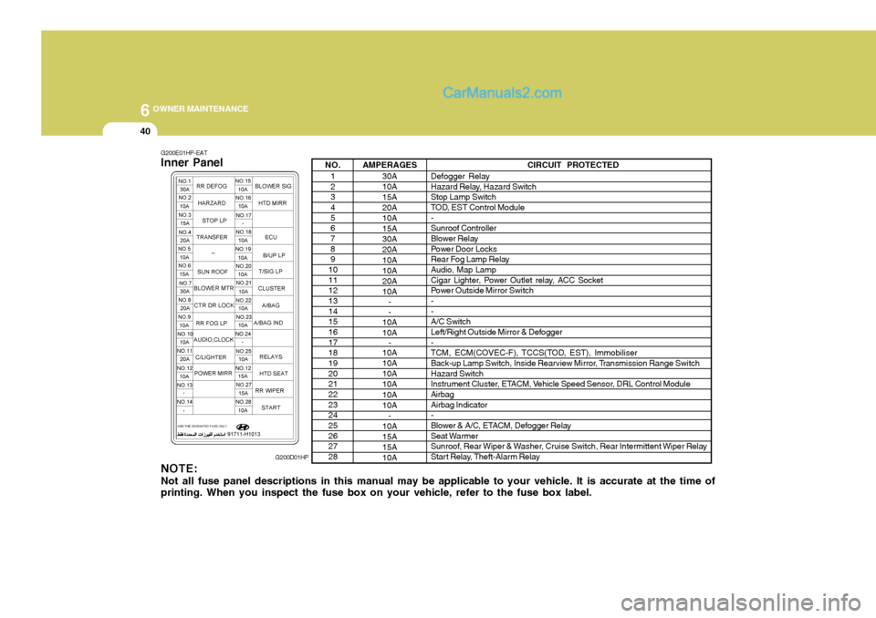
NO.1 2 34 5 67 8 9
10 11 1213 14 1516 17 1819 20 2122 23 2425 26 2728 AMPERAGES
30A 10A 15A 20A10A15A30A20A 10A 10A20A10A- -
10A 10A -
10A10A10A10A 10A 10A
-
10A15A15A 10A CIRCUIT PROTECTED
Defogger Relay
Hazard Relay, Hazard Switch Stop Lamp Switch
TOD, EST Control Module - Sunroof Controller
Blower Relay
Power Door Locks
Rear Fog Lamp RelayAudio, Map Lamp
Cigar Lighter, Power Outlet relay, ACC Socket
Power Outside Mirror Switch- - A/C Switch
Left/Right Outside Mirror & Defogger -
TCM, ECM(COVEC-F), TCCS(TOD, EST), Immobiliser
Back-up Lamp Switch, Inside Rearview Mirror, Transmission Range Switch Hazard Switch
Instrument Cluster, ETACM, Vehicle Speed Sensor, DRL Control ModuleAirbag Airbag Indicator -
Blower & A/C, ETACM, Defogger Relay
Seat Warmer
Sunroof, Rear Wiper & Washer, Cruise Switch, Rear Intermittent Wiper Relay
Start Relay, Theft-Alarm Relay
G200E01HP-EAT Inner Panel NOTE: Not all fuse panel descriptions in this manual may be applicable to your vehicle. It is accurate at the time of printing. When you inspect the fuse box on your vehicle, refer to the fuse box label. G200D01HP
Page 535 of 539
10INDEX
2
A Air Cleaner Filter ........................................................ 6-12
Air Conditioning
Maintenance ........................................................... 6-20
Operation ................................................................ 1-97
Switch ..................................................................... 1-97
Airbag ........................................................................ 1-40
Antenna ................................................................... 1-108
Apperance Care ........................................................... 4-1
Ashtray ...................................................................... 1-68
Automatic Heating and Cooling Control System ........ 1-99
BBattery ....................................................................... 6-27
Bi-Level Heating ........................................................ 1-95
Bonnet Release ......................................................... 1-83
Brake
Anti-lock system (ABS) .......................................... 2-21
Brake system checking .......................................... 6-18
Effective braking ..................................................... 2-22
Fluid ........................................................................ 6-18
Pedal clearance ...................................................... 6-24
Pedal free-play ........................................................ 6-23
CCatalytic Converter ...................................................... 7-3
Centre Console Compartment ....................................1-74
Child Restraint System .............................................. 1-31
Child-Proof Rear Door Lock ....................................... 1-10Cigar Lighter
.............................................................. 1-67
Climate Control Air Filter ................................ 1-105, 6-22
Clock ......................................................................... 1-66
Clutch Checking fluid ......................................................... 6-19
Pedal free-play ........................................................ 6-23
Cooling Fans ............................................................. 6-28
Cruise Control ............................................................ 1-87
D Daily Operating Checks ............................................... 6-4
Defrosting/Defogging .................................................. 1-96
Door
Central door locks .................................................. 1-11
Locking, unlocking front door with a key .................. 1-9
Drink Holder ............................................................... 1-69
Drive Belts ................................................................. 6-24
Driving Driving for economy ............................................... 2-23
Smooth corneri ng .................................................... 2-24
Winter motoring ...................................................... 2-24
E EGR system ................................................................ 7-5
Emission Control Systems .......................................... 7-2 Engine Before starting the engine ........................................ 2-3Compartment (3.5 V6) .............................................. 6-2
Compartment (2.9 CRDi) ........................................... 6-3
Coolant ..................................................................... 6-9
Page 536 of 539

10
INDEX
3
Coolant temperature gauge .....................................1-57
If the engine overheats ............................................. 3-4
Number ..................................................................... 8-2
Oil ............................................................................. 6-4 Starting ..................................................................... 2-5
Engine Exhaust Can Be Dangerous! ........................... 2-2
Exhaust Gas Warning .................................................. 7-2
F Fan Speed Control ................. .........................1-91, 1-102
Fog Light Switch
Front ....................................................................... 1-62
Rear ........................................................................ 1-62
Four-Wheel Drive(4WD) ............................................. 2-14
Front Door Edge Warning Light ................................. 1-85
Front Seats Adjustable head restraints ...................................... 1-17
Adjusting seatback angle ....................................... 1-17
Driver's seat lumbar support control .......................1-18
Seat adjust ment ..................................................... 1-16
Seat cushion height adjustment ............................. 1-19
Seat fore/aft adjustment ......................................... 1-16
Fuel
Capacity ................................................................... 9-2
Gauge ..................................................................... 1-57
Recommendations .................................................... 1-2
Fuel-Filler Flap
Remote release ...................................................... 1-82
Full-time 4WD Operation ............................................ 2-17
Fusible Links ............................................................. 6-25G
Glove Box ................................................................. 1-73
H Hatchback Door ......................................................... 1-78
Hazard Warning System ............................................ 1-65
Headlight Aiming Adjustment..................................... 6-33
Headlight Bulbs Replacement ....................................6-31
Headlight Leveling Device S ystem ............................1-86
Heated Front/Rear Window .. ......................................1-65
Heating and Cooling Control ......................................1-90
Heating and Ventilation
Air flow control ............................................. 1-92, 1-103
Air intake control ......................................... 1-92, 1-102
Defrosting/Defogging ............................................... 1-96
Fan speed control ........................................ 1-91, 1-102
Temperature control ................................................ 1-94
High-Mounted Rear Stop Light ...................................1-82
Horn ........................................................................... 1-85
I Ignition Switch ............................................................. 2-4
Illuminated ignition switch ......................................... 1-8
Immobiliser System ..................................................... 1-5
Indicator and Warning Lights ..................................... 1-50
Instrument Cluster and Indicator Lights ..................... 1-46
Interior Light ............................................................... 1-72
Interior Rearview Mirror .............................................. 1-77
Intermittent Wi pe Facility ........................................... 1-64