Page 247 of 539

6 DO-IT-YOURSELF MAINTENANCE
20
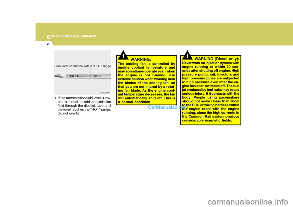
Fluid level should be within "HOT" range
3. If the transmission fluid level is low,
use a funnel to add transmission fluid through the dipstick tube until the level reaches the "HOT" range. Do not overfill. G110D04HP
!!WARNING:
The cooling fan is controlled by engine coolant temperature and may sometimes operate even whenthe engine is not running. Use extreme caution when working near the blades of the cooling fan, sothat you are not injured by a rotat- ing fan blade. As the engine cool- ant temperature decreases, the fanwill automatically shut off. This is a normal condition. WARNING (Diesel only):
Never work on injection system with
engine running or within 30 sec- onds after shutting off engine. High pressure pump, rail, injectors and high pressure pipes are subjectedto high pressure even after the en- gine has been switched off. The fuel jet produced by fuel leaks may causeserious injury, if it contacts with the body. People using pacemakers should not move closer than 30cmto the ECU or wiring harness within the engine room with the engine running, since the high currents inthe Common Rail system produce considerable magnetic fields.
Page 260 of 539
6
DO-IT-YOURSELF MAINTENANCE
33
Gasoline Engine or Diesel Engine (2.5 TCI)
POWER STEERING FLUID LEVEL
G220B01A-AAT
Checking Engine Cooling Fan
The engine cooling fan should come
on automatically if the engine coolant temperature is high.
G220C01A-AAT
Checking Condenser Cooling Fan
The condenser cooling fan should
come on automatically whenever the air conditioning is in operation. G230A03A-AAT The power steering fluid level should be checked daily.G230A01HP
HHP5014CHECKING ELECTRIC COOLING FANS
!
G220A01A-AAT WARNING:
The cooling fan is controlled by
engine coolant temperature and may sometimes operate even whenthe engine is not running. Use extreme caution when working near the blades of the cooling fan,so that you are not injured by a rotating fan blade. As the engine coolant temperature decreases thefan will automatically shut off. This is a normal condition.
Diesel Engine (2.9 CRDi)
Page 276 of 539

7EMISSION CONTROL SYSTEMS
2EMISSION CONTROL SYSTEMS
H010A01A-GAT
(If Installed)
Your Hyundai is equipped with an
emission control system to meet all requirements of the Emission prohibi- tion rules of your province.
There are three emission control sys-
tems which are as follows.
(1) Crankcase emission control sys- tem (For a Gasoline Engine)
(2) Evaporative emission control sys- tem (For a Gasoline Engine)
(3) Exhaust emission control system
In order to assure the proper function
of the emission control systems, it is recommended that you have your carinspected and maintained by an au- thorized Hyundai dealer in accordance with the maintenance schedule in thismanual. H010B01A-AAT
1. Crankcase Emission Control
System ; For a Gasoline Engine
The positive crankcase ventilation
system is employed to prevent air pollution caused by blow-by gasesbeing emitted from the crankcase. This system supplies fresh filtered air to the crankcase through the air in-take hose. Inside the crankcase, which the fresh air mixes with blow-by gases, which then pass through the PCVvalve into the induction system.
H010C02Y-GAT
2. Evaporative Emission
Control System ; For a Gasoline Engine
The Evaporative Emission Control
System is designed to prevent fuel vapors from escaping into the atmo- sphere. Canister
While the engine is inoperative, fuel
vapors generated inside the fuel tankare absorbed and stored in the canis- ter. When the engine is running, thefuel vapors absorbed in the canister are drawn into the induction system through the purge control solenoidvalve. Purge Control Solenoid Valve
The purge control solenoid valve is
controlled by the ECM; when the en- gine coolant temperature is low, and during idling, it closes, so that evapo- rated fuel is not taken into the surgetank. After engine warm-up, during ordinary driving, it opens so as to introduce evaporated fuel to the surgetank. H010D01A-AAT
3. Exhaust Emission Control
System
The Exhaust Emission Control Sys- tem is a highly effective system whichcontrols exhaust emissions while maintaining good vehicle performance.
hpflene-7.p65 3/9/2005, 1:52 PM
2
Page 355 of 539

1
CONTROLS AND EQUIPMENT
47
1. Tachometer
2. Turn Signal Indicator Light
3. Coolant Temperature Gauge
4. Fuel Gauge
5. Speedometer
6. ABS Service Reminder Indicator(SRI) (Not all models)
7. Supplemental Restraint (AirBag) System Service Reminder lndicator (SRI)
8. Low Oil Pressure Warning Light
9. Parking Brake/Low Brake Fluid LevelWarning Light
10. Charging System Warning Light
11. A/T Oil Temperature Warning Light (Not all models)
12. Overdrive OFF Indicator Light (Not all models)
13. High Beam Indicator Light 14. Front Fog Indicator Light
15. Automatic Transmission Position Indicator Light (Not all models)
16. Cruise Indicator Light (Not all models)
17. 4WD LOW Indicator Light
18. 4WD HIGH Indicator Light (Part-time 4WD)
/4WD System Warning Light (Full-time 4WD)
19. Malfunction Indicator Light (MIL)
20. Trip Odometer
21. Odometer 22.Trip odometer Reset Knob
23. Tailgate Door Open Warning Light
24. Door Open (Ajar) Warning Light
25. Seat Belt Warning Light
26. Low Fuel Warning Light
Page 357 of 539

1
CONTROLS AND EQUIPMENT
49
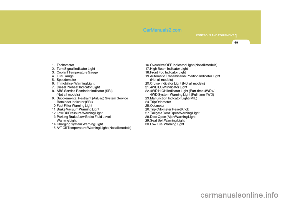
1. Tachometer
2. Turn Signal Indicator Light
3. Coolant Temperature Gauge
4. Fuel Gauge
5. Speedometer
6. Immobiliser Warning Light
7. Diesel Preheat Indicator Light
8. ABS Service Reminder Indicator (SRI) (Not all models)
9. Supplemental Restraint (AirBag) System Service Reminder Indicator (SRI)
10. Fuel Filter Warning Light
11. Brake Vacuum Warning Light
12. Low Oil Pressure Warning Light
13. Parking Brake/Low Brake Fluid Level Warning Light
14. Charging System Warning Light
15. A/T Oil Temperature Warning Light (Not all models) 16. Overdrive OFF Indicator Light (Not all models)
17. High Beam Indicator Light
18. Front Fog Indicator Light
19. Automatic Transmission Position Indicator Light
(Not all models)
20. Cruise Indicator Light (Not all models)
21. 4WD LOW Indicator Light
22. 4WD HIGH Indicator Light (Part-time 4WD) / 4WD System Warning Light (Full-time 4WD)
23. Malfunction Indicator Light (MIL)
24. Trip Odometer
25. Odometer
26. Trip Odometer Reset Knob
27. Tailgate Door Open Warning Light
28. Door Open (Ajar) Warning Light
29. Seat Belt Warning Light
30. Low Fuel Warning Light
Page 365 of 539
1
CONTROLS AND EQUIPMENT
57
!
B270A01A-EAT BRAKE PAD WEAR WARNING SOUND The front disc brake pads have wear indicators that should make a high-pitched squealing or scraping noise when new pads are needed. The sound may come and go or be heard all thetime when the vehicle is moving. It may also be heard when the brake pedal is pushed down firmly. Exces-sive rotor damage will result if the worn pads are not replaced. See your Hyundai authorised repairer immediately. B290A02A-EAT COOLANT TEMPERATURE GAUGE
The needle on the gauge indicates the approximate fuel level in the fuel tank. The fuel capacity is given in Section 9. WARNING:
Never remove the radiator cap when the engine is hot. The coolant is under pressure and could erupt and cause severe burns. Wait until theengine is cool before removing the radiator cap.
INSTRUMENT CLUSTER
B280A01A-AAT FUEL GAUGE
HHP2080
HHP2081
Page 366 of 539
1CONTROLS AND EQUIPMENT
58
The needle on the coolant temperature gauge should stay in the normal range.If it moves across the dial to "H" (Hot), pull over and stop as soon as possible and turn off the engine. Then open thebonnet and check the coolant level and the water pump drive belt. If you sus- pect cooling system trouble, have yourcooling system checked by Hyundai authorised repairer as soon as pos- sible.
! CAUTION:
The engine should not be raced to such a speed that the needle enters the red zone on the tachometer face. This can cause severe engine dam-age and may void your warranty.
B330A01L-AAT TACHOMETER The tachometer registers the speed of your engine in revolutions per minute (rpm).Petrol Engine
B330A01HP
HHP2078
Diesel Engine
Page 443 of 539

2
DRIVING YOUR HYUNDAI
27
!
CAUTION:
o Never connect a trailer brake sys- tem directly to the vehicle brake system.
o When towing a trailer on steep grades (in excess of 6%) pay closeattention to the engine coolanttemperature gauge to ensure the engine does not overheat. If the needle of the coolant temperaturegauge moves across the dial to- wards "H" (HOT), pull over and stop as soon as it is safe to do so,and allow the engine to idle until it cools down. You may proceed once the engine has cooled suffi-ciently. YC200D2-E Safety Cables Should the towbar connection between your car and the trailer or vehicle youare towing fail, the trailer or vehicle could wander dangerously across other lanes of traffic and ultimately leave theroadway. To eliminate this potentially dangerous situation, a safety cable, attached between your car and thetrailer or towed vehicle, are required.
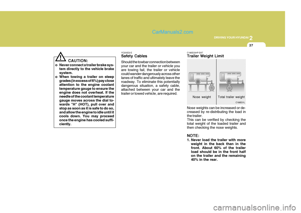
C190E03HP-EAT Trailer Weight Limit Nose weights can be increased or de- creased by re-distributing the load in the trailer.This can be verified by checking the total weight of the loaded trailer and then checking the nose weights. NOTE:
1. Never load the trailer with more
weight in the back than in the front. About 60% of the trailerload should be in the front half on the trailer and the remaining 40% in the rear.
C190E01L
Nose weight Total trailer weight