Page 163 of 484
SA-52
8. Mount the inner oil seal óon the steering knuckle.
Check the oil seal visually, if any deformation or glue lack is
found, change the oil seal
Mount of Steering Knuckle
1. Mount the lower ball stud on the steering knuckle;
Connect the lower ball stud and the steering knuckle with
bolts, and screw up the bolts according to the specified torque.
Fastening torque�(70-90)N�m
2. Mount on the steering knuckle
(a) Coat the lubricant HP-R on the drive shaft.
(b) Press down the lower arm to mount on the steering
knuckle.
(c) Mount on the groove nut of lower ball stud and screw up
the nut according to the specified torque, and then mount
on the split pin.
Fastening torque�(132-152)N�m
(d) Mount on the groove nut of upper ball stud and screw up
the nut according to the specified torque, and then mount
on the split pin.
Fastening torque�(132-152)N�m
Suspension System and Automobile Axle (SF/4WD)�Front Wheel Hub and Steering Knuckle (Steering Knuckle)
Page 164 of 484
SA-53
3. Mount the stabilizer rod on the lower arm.
Fastening torque�(20-26)N�m
4. Mount the vibration damper on the lower arm.
Fastening torque�(127-147)N�m
5. Mount the steering knuckle arm and the brake oil pipe
bracket on the steering knuckle, and coat the sealing
agent 1271 on the bolt thread.
Fastening torque�180N�m
6. Mount on the dust cover and the brake shell.
Align the locating hole of dust cover and the groove of the
steering knuckle so as to guarantee the dust cover and the
steering knuckle are concentric.
Fastening torque�(25-29)N�m
7. Mount the front wheel hub and the front brake disc as well
as the brake caliper.
8. Check the height of the brake liquid level and, if required,
add the brake liquid, exhaust the gas of the braking
system.
Suspension System and Automobile Axle (SF/4WD) �Front Wheel Hub and Steering Knuckle (Steering Knuckle)
Page 166 of 484
SA-55
3. Tear down the retainer ring from the drive shaft with the
calipers, and take down the washer-steering knuckle
shaft spline.
4. Tear down the front wheel hub and the steering knuckle
together.
5. Screw off the nuts that connect the constant speed drive
shaft to take down the constant speed drive shaft.
6. Check and repair the constant speed drive shaft
Inject the molybdenum disulphide lithium grease of 100-110
g in the end of ball-cage type universal joint and the end of
axially movable tripod universal joint.
The ball-cage type universal joint and the axially movable
tripod universal joint should swing freely, and no clipping
stagnant is allowed. The dust cover should be prevented from
deformation and every gripping loop shall be clamping tightly.
Disassembly of Constant Speed Driving
Shaft
1. Tear down the brake caliper.
2. Tear down the free hub Suspension System and Automobile Axle (SF/4WD) �Constant Speed Driving Shaft
Page 167 of 484
SA-56
Mount of Constant Speed Drive Shaft
1. Mount the constant speed drive shaft on the flanges of
the long and short axle shafts.
2. Mount on the front wheel hub and the steering knuckle.
3. Mount on the washer-steering knuckle shaft spline, and
then use the caliper to mount on the retainer ring.
4. Mount on the free hub.
5. Mount on the brake caliper.
Suspension System and Automobile Axle (SF/4WD) �Constant Speed Driving Shaft
Page 168 of 484
SA-57
1. Support up the front of vehicle to tear down the front
wheel and the steering knuckle.
2. Drain off lubricant in the front speed reducer.
3. Disconnect the front speed reducer flange and the drive
shaft.
Notice: Mark the assembly marks on the speed reducer
and the drive shaft before disconnecting them.
4. Tear down the front speed reducer.
5. Tear down the flange and dust cover:
(a) Loosen the riveted position on main-tooth nut with the
hammer and chisel.
Front Speed Reducer
Change of driving bevel gear oil seal of front speed reducer
front speed reducer and
differential assembly
oil-guard tray
�driving bevel gear oil seal
flange and dust cover
140-210�
� Parts that cannot be reused after being used�specified torque
N�M
main-tooth nut
Suspension System and Automobile Axle (SF/4WD) � Front Speed Reducer (Change of Driving Bevel Gear Oil Seal of Front Speed Reducer)
Page 190 of 484
SA-79
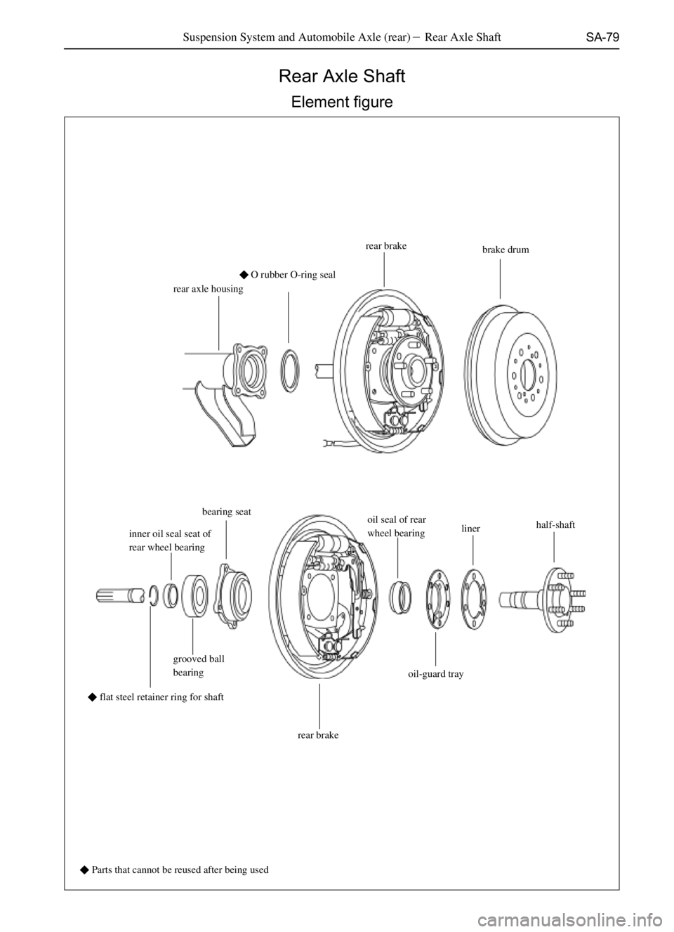
Rear Axle Shaft
Element figure
rear axle housing�O rubber O-ring sealrear brake
brake drum
inner oil seal seat of
rear wheel bearingbearing seat
oil seal of rear
wheel bearinglinerhalf-shaft
grooved ball
bearing
rear brakeoil-guard tray
� Parts that cannot be reused after being used
Suspension System and Automobile Axle (rear)�Rear Axle Shaft
�flat steel retainer ring for shaft
Page 191 of 484

SA-80
Dismantle of Rear half Axle Shaft
1. Tear down the wheels.
2. Tear down the rear brake drum.
3. Tear down the grab end of the bracing wire of hand brake
from the rear brake.
4. Tear down the half-shaft and the rear brake assembly
from the rear axle housing.
5. Tear down the flat steel retainer ring for shaft from the
half-shaft;
Tear down the flat steel retainer ring for shaft with the ring
calipers.
6. Tear down the half-shaft:
Put down a wooden plate on the flat ground, and thrust the end
of spline of half-shaft and rear brake assembly toward the
wooden plate to separate the shaft and the rear brake assembly.
Inspection on and repairing of half-shaft parts
1. Check the wear, damage and swing difference half-shaft
and the flange.
Max shaft run-out: 2 mm
Max flange run-out: 0.2 mm
In case the half-shaft is damaged, or wearied or the measuring
value of the swing difference is excessive, change the half-
shaft.
2. Check he oil seal of rear wheel bearing:
Check to see whether there is wear or damage, and change the
oil seal if necessary.
3. The disassembly of the outer oil seal of rear wheel
bearing;
Tear down the outer oil seal of rear wheel bearing with SST. Suspension System and Automobile Axle (rear)� Rear Half Axle Shaft
Page 192 of 484
 Press out the grooved ball bearing with SST.
(b) Pr")
SA-81
4. Check the grooved ball bearing
Check the grooved bearing to see whether there is damage or
wear.
5. Change the bearing where necessary:
(a) Press out the grooved ball bearing with SST.
(b) Press in the new grooved ball bearing with SST.
6. Mount the new oil seal of rear wheel bearing.
Press in the new oil seal of rear wheel bearing with SST
Coat moderate lithium base grease on the lip open of oil seal.
7. Check the bearing seat.
Check the wear or damage situation.
8. Change the bearing seat where necessary:
(a) Tear down the oil seal of rear wheel bearing and the
grooved ball bearing with SST.
(b) Tap the bolts with copper bar to tear down the bearing seat.
(c) Mount the new grooved ball bearing and the oil seal of
rear wheel bearing on the bearing seat
(d) Press the rear brake, which is put on with bolts, in the
bearing seat.
9. Check the wear or damage of the inner oil seal of the rear
wheel bearing.
10. Change the rear wheel bearing where necessary:
(a) Tear down the oil seal of rear wheel bearing with SST. Suspension System and Automobile Axle (rear)�Rear half Axle Shaft