Page 145 of 425

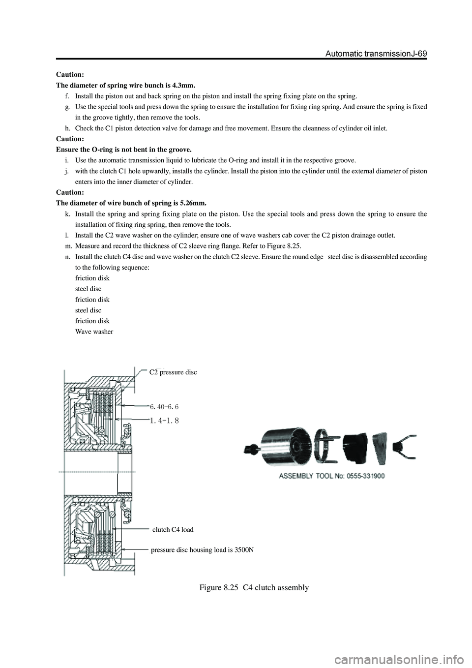
Figure 8.25 C4 clutch assembly
Caution:
The diameter of spring wire bunch is 4.3mm.
f. Install the piston out and back spring on the piston and install the spring fixing plate on the spring.
g. Use the special tools and press down the spring to ensure the installation for fixing ring spring. And ensure the spring is fixed
in the groove tightly, then remove the tools.
h. Check the C1 piston detection valve for damage and free movement. Ensure the cleanness of cylinder oil inlet.
Caution:
Ensure the O-ring is not bent in the groove.
i. Use the automatic transmission liquid to lubricate the O-ring and install it in the respective groove.
j. with the clutch C1 hole upwardly, installs the cylinder. Install the piston into the cylinder until the external diameter of piston
enters into the inner diameter of cylinder.
Caution:
The diameter of wire bunch of spring is 5.26mm.
k. Install the spring and spring fixing plate on the piston. Use the special tools and press down the spring to ensure the
installation of fixing ring spring, then remove the tools.
l. Install the C2 wave washer on the cylinder; ensure one of wave washers cab cover the C2 piston drainage outlet.
m. Measure and record the thickness of C2 sleeve ring flange. Refer to Figure 8.25.
n. Install the clutch C4 disc and wave washer on the clutch C2 sleeve. Ensure the round edge steel disc is disassembled according
to the following sequence:
friction disk
steel disc
friction disk
steel disc
friction disk
Wave washer
C2 pressure disc
pressure disc housing load is 3500N
clutch C4 load
Page 182 of 425
2. Place in the bearing inner race; use the fill the gap
between the inner and outer race of the bearing up
with the HP-R grease.grease
grease
3. Install the inner bearing and oil seal
a. Place the inner bearing in the hub.
b. Use the special tools to knock the new oil seal into the hub.
c. Coat the oil seal lip with HP-R grease.
4. Install the hub on the steering knuckle
a. Install the hub on the steering knuckle.
b. Install the external bearing.
diagram of spe-
cial tools
special tools
5. Adjust the pre-applied load
a. Use the special tools to screw on the locknut to specified torque.
Tightening force: 80-100N
m
b. Rotate the hub to right and left 1/3
1/4 round respectively.
c. Screw off the nut until the nut can be loosed by hand.
d. Use the special tools to retighten the lock nut.
Tightening force: 28N
m
e. Use the spring tension meter to check the pre-applied load.
Pre-applied load (for starting): 28-56N
diagram of spe-
cial tools
special tools
Page 204 of 425
2. Place in the bearing inner race; use the fill the gap
between the inner and outer race of the bearing up
with the HP-R grease.grease
grease
3. Install the inner bearing and oil seal
a. Place the inner bearing in the hub
b. Use the special tools to knock the new oil seal into the hub.
c. Coat the oil seal lip with HP-R grease.diagram of
special tools
special tools
4. Install the hub on the steering knuckle
a. Install the hub on the steering knuckle
b. Install the outer bearing.
5. Adjust the pre-applied load
a. Use the special tools to screw on the locknut to specified
torque.
Tightening force: 80-100N
m
b. Rotate the hub to right and left 1/3
1/4 round respectively.
c. Screw off the nut until the nut can be loosed by hand.
d. Use the special tools to retighten the lock nut.
Tightening force: 28N
m
e. Use the spring tension meter to check the pre-applied load.
Pre-applied load (for starting): 28-56N
special
tools
diagram of
special tools
Page 231 of 425
6Install the inner trumpet connector on the front
drive shaft
a. Fill the inner trumpet connector and inner jacket with the
grease supplied with the jacket
(Recommend used grease is CAPLEX or KY1). Amount About140g
b. Align the assembly mark made during disassembly; covered
with inner trumpet connector.
c. Cover the inner jacket on the inner trumpet connector.
7Use the inner and outer jacket clip pliers to
clamp the inner and outer jacket.
a. Use the special non-ear clip pliers to lock the large clip of
inner jacket.
b. Use the nutcracker to lock the small clip of inner jacket.
Caution: Ensure the large and small connecting place of jacket
is in the corresponding groove of trumpet connector and shaft.
assembly mark
outer jacket clip
inner jacket clip
non-ear clip pliers
nutcracker
Page 245 of 425
9. Remove the sealant on the matching surface
between the flange and electric clutch housing by
knife.
Caution: Do not scratch the matching surface.
10. Use the special tools to knock the new seal in the
oil seal position in flange.
Caution: Before install the new oil seal, it should
coat the lip with thin lithium base grease, and the oil
seal should be in alignment position.
11. Insert the spline of small end of major semiaxle
in the spline of front reducer half axle gear slightly,
then use the brass bar and hand hammer to knock it
in.
Caution: When knock in the major semiaxle, must
not damage the inside needle bearing of large end
spline of major semiaxle.
12. Use the circlip pliers to install the circlip in the
flange and clamp the bearing outer race.
Caution: The circlip should be replaced if it has
serious deformation.
13. Use the clean cloth to wipe the matching surface
of flange and electric clutch housing respectively.
Page 259 of 425
8. Place the differential assembly on the corresponding
position of front reducer housing.
9.Select an adjusting shim and insert it in a side of
side bearing outer race; push the differential assem-
bly to the side with adjusting shim.
10. Use the dial indicator to measure the gear side
clearance of driven bevel gear and drive bevel gear;
select out the adjusting shim in the side which meets
the rational clearance of 0.15mm.
11.Measure the thickness of the adjusting shim.
12. After select out one side adjusting shim, then
select theadjusting of another side according to that
the theoreticthickness of the adjusting shimofanother
side equals to subtracting the thickness of selected
shim and oppositiondistance L2 between outer race of
two side bearings of differential assembly from the
opposition distance L1 between two side bearings of
front reducer housing.
Page 262 of 425
d. Remove the drive bevel gear and use the special toolsto remove
the large bearing of drive bevel gear beforereplacethe adjusting
washer.
e. Insert the new adjusting washer and usethespecial tools to
press in the large bearing of drivebevel gear.
f. Place the adjusting washer above the large bearing on the
drive bevel gear, install the spacer in the reducer housing;
install the drive gear flange andtighten the nut to the specified
torque.
g. Remeasure the pre-applied load of drive gear bearing clearance
and the total pre-applied load of reducer; ensure it meets the
requirement.
21. Use the dial indicator to measure the axial and
radial run-out tolerance of . Drive bevel gear flange.
Max. Axial runout : 0.1mm
Max. Radial run-out tolerance: 0.1mm
Remarks: It should check the big and small bearing of drive
bevel gear when the runout is more than 0.1mm.
22. Rivet the nut of drive bevel gear.
Page 263 of 425

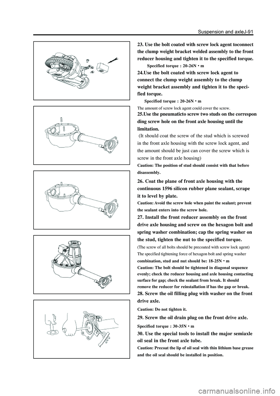
23. Use the bolt coated with screw lock agent toconnect
the clump weight bracket welded assembly to the front
reducer housing and tighten it to the specified torque.
Specified torque : 20-26Nm
24.Use the bolt coated with screw lock agent to
connect the clump weight assembly to the clump
weight bracket assembly and tighten it to the speci-
fied torque.
Specified torque : 20-26Nm
The amount of screw lock agent could cover the screw.
25.Use the pneumaticto screw two studs on the correspon
ding screw hole on the front axle housing until the
limitation.
26. Coat the plane of front axle housing with the
continuous 1596 silicon rubber plane sealant, scrape
it to level by plate.
Caution: Avoid the screw hole when paint the sealant; prevent
the sealant enters into the screw hole.
27. Install the front reducer assembly on the front
drive axle housing and screw on the hexagon bolt and
spring washer combination; cap the spring washer on
the stud, tighten the nut to the specified torque.
(The screw of all bolts should be precoated with screw lock agent)
The specified tightening force of hexagon bolt and spring washer
combination, stud and nut should be: 18-25N
m
Caution: The bolt should be tightened in diagonal sequence
evenly; check the reducer housing and axle housing contacting
surface for gap; check the sealant from break. It should
remove the reducer for reinstallation if has the gap or break.
28. Screw the oil filling plug with washer on the front
drive axle.
Caution: Do not tighten it.
29. Screw the oil drain plug on the front drive axle.
Specified torque : 30-35Nm
30. Use the special tools to install the major semiaxle
oil seal in the front axle tube.
Caution: Precoat the lip of oil seal with thin lithium base grease
and the oil seal should be installed in position.
(It should coat the screw of the stud which is screwed
in the front axle housing with the screw lock agent, and
the amount should be just can cover the screw which is
screw in the front axle housing)
Caution: The position of stud should consist with that before
disassembly.