2006 GREAT WALL HOVER tyre pressure
[x] Cancel search: tyre pressurePage 174 of 425

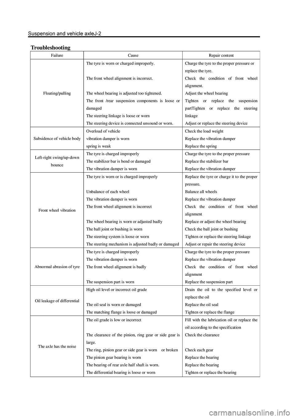
Troubleshooting
Failure Cause Repair cont ent
Floating/pulling The t yre is worn or charged improperly.
The front wheel alignment is incorrect.
The wheel bearing is adjusted too tightened.
The front /rear suspension components is loose or
damaged
The steering linkage is loose or worn
The steering device is connect ed unsound or worn. Charge the t yre to the prop er pressur e or
repla ce the t yre.
Check the condition of front wheel
alignment.
Adjust the wheel bearing
Tighten or replace the suspension
partTighten or replace the steering
linkage
Adjust or replace the steering device
Subsidence of vehicle body Overload of vehicle
vibration damper is worn
spring is weak Check the load weight
Replace the vibration damper
Replace the spring
Left-right swing/up-down
bounce The t yre is charged improperly
The stabilizer bar is bend or damaged
The vibration damper is worn Charge the t yre to the prop er pressur e
Replace the stabilizer bar
Replace the vibration damper
Front wheel vibration The t yre is worn or is charged improperly
Unbalance of each wheel
The vibration damper is worn
The front wheel alignment is incorrect
The wheel bearing is worn or adjusted badly
The ball joint or bushing is worn
The steering system is loose or worn
The steering mechanism is adjusted badly or damaged Repla ce the t yr e or char ge it to the prop er
pressure.
Balance all wheels
Replace the vibration damper
Check the condition of front wheel
alignment
Replace or adjust the wheel bearing
Check the ball joint or bushing
Tighten or replace the steering linkage
Adjust or repair the steering device
Abnormal abrasion of tyre The t yre is charged improperly
The vibration damper is worn
The front wheel alignment is badly
The suspension part is worn Charge the t yre to the prop er pressur e
Replace the vibration damper
Check the condition of front wheel
alignment
Replace the suspension part
Oil leakage of differential High oil level or incorrect oil grade
The oil seal is worn or damaged
The matching flange is loose or damaged Drain the oil to the specified level or
repla ce the oil
Replace the oil seal
Tighten or replace the flange
The axle has the nois e The oil grade is low or incorrect
The clearance of the pinion, ring gear or side gear is
large.
The ring, pinion gear or side gear is worn or broken
The pinion gear bearing is worn
The b earing of rear axle half shaft is worn.
The differential b earing is loos e or worn Fill with the lubrication oil or replace the
oil according to the specification
Check the clearance
Check each gear
Replace the bearing
Replace the bearing
Tighten or replace the bearing
Page 175 of 425

Front wheel alignment
1. Process the following inspection and eliminate
all problems
a. Check the wear condition of tyre and proper inflation.
Tyre inflation pressure: 230kPa
b. Check the wheel bearing of front wheel for loose.
c. Check the front suspension for loose.
d. Check the steering drive device for loose.
e. Process the standard elastic test; check thefrontvibration damper
for normal operation.
3. Install the 4-Wheel alignment instrument
Processed according to the detailed description of equipment
manufacturer.
4. Adjust the wheel angle
Remove the cover of spacing bolt of steering knuckle; check the internal
wheel’s steering angle A.
Internal wheel’s steering angle:
32
Caution: The wheel should not touch the brake hose of car body
when the steering wheel is rotated to limit.
2. Adjust the height of car
A:Adjust the height of car to the standard value for theconvenience of
processing the front wheel alignmentinspection.
B: Front fixed bolt of lower suspension arm
The standard no-load height is: the center of front fixed boltof lower
suspension arm is 295
1mm away form theground.
Page 288 of 425

Brake-2
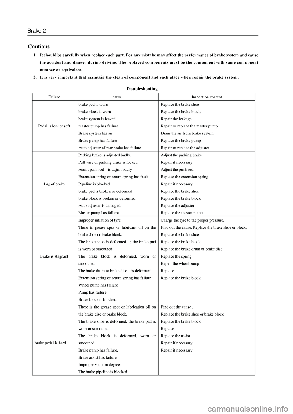
Troubleshooting
Cautions
Failure cause Inspection content
Pedal is low or soft brake pad is worn
brake block is worn
brake system is leaked
master pump has failure
Brake system has air
Brake pump has failure
Auto adjuster of rear brake has failure Replace the brake shoe
Replace the brake block
Repair the leakage
Repair or replace the master pump
Drain the air from brake system
Replace the brake pump
Repair or replace the adjuster
Lag of brake Parking brake is adjusted badly.
Pull wire of parking brake is locked
Assist push rod is adjust badly
Extension spring or return spring has fault
Pipeline is blocked
brake pad is broken or deformed
brake block is broken or deformed
Auto adjuster is damaged
Master pump has failure. Adjust the parking brake
Repair if necessary
Adjust the push rod
Repla ce the extension spring
Repair if necessary
Replace the brake shoe
Replace the brake block
Repla ce the a djuster
Repla ce the master pump
Brake is stagnant Improper inflation of tyre
There is grease spot or lubricant oil on the
brake shoe or brake block.
The brake shoe is deformed ; the brake pad
is worn or smoothed
The brake block is deformed, worn or
smoothed
The brake drum or brake disc is deformed
Extension spring or return spring has failure
Wheel pump has failure
Pump has failure
Brake block is blocked Charge the tyre to the proper pressure.
Find out the cause. Replace the brake shoe or block.
Replace the brake shoe
Replace the brake block
Replace the brake drum or brake disc
Repla ce the spring
Repair the wheel pump
Replace
Replace the brake block
brake pedal is hard There is the grease spot or lubrication oil on
the brake disc or brake block.
The brake shoe is deformed; the brake pad is
worn or s moothed
The brake block is deformed, worn or
smoothed
Brake pump has failure.
Brake assist has failure
Improper vacuum degree
The brake pipeline is blocked. Find out the caus e .
Replace the brake shoe or brake block
Replace the brake block
Replace
Replace the assist
Repair if necessary
Repair if necessary
Page 317 of 425

Brake-31
Antilock Braking System (ABS)
Cautions
1. It must not remove or install the electric elements and wire bunch plug when the ignition switch is in ON to avoid
the damage of ECU. It should turn off the ignition switch if needs disassembly.
2. Pay attention to do not knock or impact the ABS ECU during the maintenance and repair, for it will damage the
ABS ECU easily.
3. The wheel speed sensor and hydraulic unit (integrated with ECU) of BOSCH ABS8.0 can not be repaired, it should
be replaced in integral if damaged.
4. After the brake system is maintained, the brake pedal maybe soft. Discharge the air according to the normal brake
system.
5. It must use the brake fluid from original manufacturer; the brake fluid of different number cannot be used in mixed,
otherwise it will cause the failure of brake system. Select the tyre of original type as most as possible
Repair of Antilock Braking System (ABS)
1. It should process the failure diagnosis for the brake system before process the ABS failure diagnosis. It can
diagnose out the failure rapidly by using Table 1. In Table 1, the small number means the failure which occurs most
possibly. Check each element according to the sequence and maintain or replace it if necessary.
2. Check the following elements for normal operation before the diagnosis:
Brake fluid level and brake fluid quality
Pressure of tyre, size of tyre, shape and depth of tyre figure
Other brake component
These components will affect the brake effect of the ABS. Check the system sensor, connecting wire and connector for correct
installation, arrangement and connection. Ensure the completeness of fuse, repair or replace it if necessary.
3. Process the analysis and diagnosis according to the ABS advanced by owner. Use the diagnosis instrument (Annex
1) for final check and confirmation. It must process the run inspection after the competition of all ABS maintenance.
The test condition is shown as follows:
a. Confirm the tyre complies with the requirement, the tyre pressure is normal.
b. The brake system (including brake light ) is normal
c. The brake system is without leakage.
d. The position and installation of wheel speed sensor is correct.
e. All fuses are normal.
4. test method:
Run for 1 min at least when the vehicle speed is beyond 40Km/h, process a proper brake. Then read out the failure code to
ensure the ABS is without failure code.