Page 225 of 425
1. Place the car in the middle of repair platform or
trench, support the front of the car steadily(support
on the carriage) then remove the left and right
front wheel. (make the car in 2WD status before
the disassembly)
2. Remove the beam on the lower of front drive axle
assembly.
3. Disconnect the connection of front drive axle
flange and drive shaft and make the assembly
mark
4. Drain the lubrication oil in reducer.
bolt
front hub cover
circlip
adjusting washer set
flange
disconnect three ports in this position
N m: specified torque
Page 246 of 425

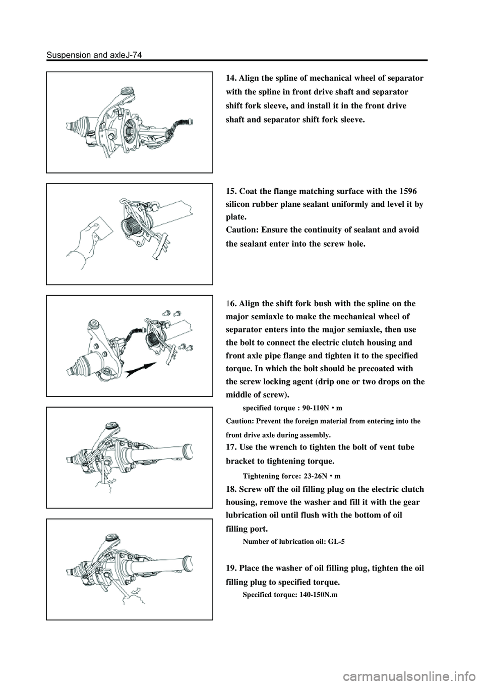
14. Align the spline of mechanical wheel of separator
with the spline in front drive shaft and separator
shift fork sleeve, and install it in the front drive
shaft and separator shift fork sleeve.
15. Coat the flange matching surface with the 1596
silicon rubber plane sealant uniformly and level it by
plate.
Caution: Ensure the continuity of sealant and avoid
the sealant enter into the screw hole.
16. Align the shift fork bush with the spline on the
major semiaxle to make the mechanical wheel of
separator enters into the major semiaxle, then use
the bolt to connect the electric clutch housing and
front axle pipe flange and tighten it to the specified
torque. In which the bolt should be precoated with
the screw locking agent (drip one or two drops on the
middle of screw).
specified torque : 90-110Nm
Caution: Prevent the foreign material from entering into the
front drive axle during assembly.
17. Use the wrench to tighten the bolt of vent tube
bracket to tightening torque.
Tightening force: 23-26Nm
18. Screw off the oil filling plug on the electric clutch
housing, remove the washer and fill it with the gear
lubrication oil until flush with the bottom of oil
filling port.
Number of lubrication oil: GL-5
19. Place the washer of oil filling plug, tighten the oil
filling plug to specified torque.
Specified torque: 140-150N.m
Page 248 of 425
Disassembly and assembly of front reducer assembly and electric clutch
adjusting shim
bearing gland
differential housing
driven bevel gear
front drive axle housing
washer
oil filling plug
vent tube
clip
front axle vents tube
connector assembly
major semiaxle
needle bearingelectric clutch
location pin
vent tube
mechanical wheel of separator
declutch shift sleeve
electric clutch housing
oil filling plug
circlip
major semiaxle oil seal
half axle gear thrust plate
half axle gear
planetary gear shaft
planetary gear
bolt clump
weight bracketclump weight and bush
assembly
clump weight bracket
welded assembly
front reducer
housing
adjusting washerspacer
drive bevel gear
small bearingoil sealfront drive gear flange and
dustproof cover assembly
drive bevel gearadjusting washer
Pregummed component
N m: Specified torque
Used component which
can not be used any more.bearing
circlip
big bearing
Page 268 of 425
Axle drving assembly
Removal of semiaxle
1. Remove the wheel.
2. Disconnect the manual brake pull-wire from the
carriage; loose the small bracket.
3. Remove the brake caliper; remove the brake disc .
4. Remove the rear halfaxle assembly from the rear
axle housing
a. Use the bolt to connect the special tools to the semiaxle flange
surface.
b. Use the hammer of special tools to remove the rear axle.
brake caliper assembly
brake disc
circlip
oil seal base
bearing
oil seal
oil seal pressing block
parking brake assembly
rear axle
N
m: Specified torque
Used component which can not be used any more.
pull-wire assembly
5. Remove the circlip from the halfaxle assembly.
Use the circlip pliers to remove the circlip.
Page 290 of 425

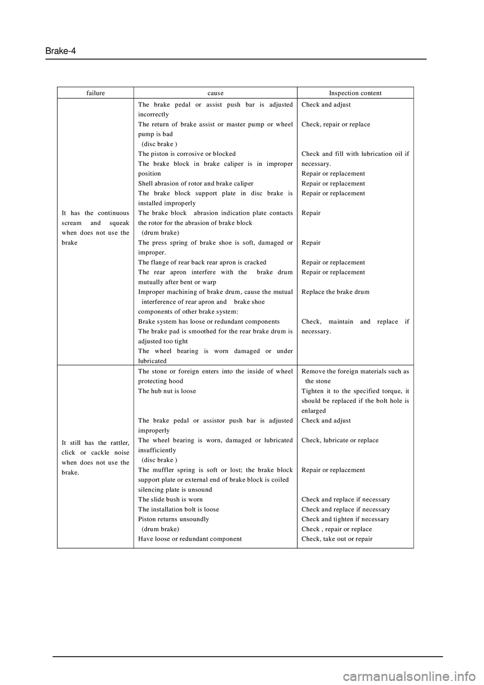
Brake-4
failure caus e Inspection content
It has the continuous
scream and squeak
when does not us e the
brake The brake pedal or assist push bar is adjusted
incorrectly
The return of brake assist or master pump or wheel
pump is bad
(dis c brake )
T he piston is corr osive or blocked
T he brake block in brake calip er is in improp er
position
Shell abrasion of rotor and brake caliper
The brake block support plate in disc brake is
installed improperly
The brake block abrasion indication plate contacts
the rotor for the abrasion of brake block
(drum brake)
The press spring of brake shoe is soft, damaged or
improper.
The flange of rear back rear apron is cracked
T he rear apron interfer e with the brake drum
mutually after bent or warp
Improper machining of brake drum , caus e the mutual
interference of rear apron and brake shoe
components of other brake s ystem :
Brake system has loose or redundant components
T he brake pad is smoothed for the rear brake drum is
adjusted too tight
The wheel bearing is worn damaged or under
lubricated Check and adjust
Check, repair or replace
Check and fill with lubrication oil if
necessary.
Repair or replacement
Repair or replacement
Repair or replacement
Repair
Repair
Repair or replacement
Repair or replacement
Replace the brake drum
Check, maintain and replace if
necessary.
It still has the rattler,
click or cackle noise
when does not us e the
brake. The stone or foreign enters into the inside of wheel
protecting hood
The hub nut is loose
The brake pedal or assistor push bar is adjusted
improperly
The wheel bearing is worn, damaged or lubricated
insufficiently
(dis c brake )
T he muffler spring is soft or lost; the brake block
support plate or external end of brake block is coiled
silencing plate is unsound
T he slide bush is worn
T he installation bolt is loos e
Piston returns unsoundly
(drum brake)
Have loose or redundant component Remove the foreign materials such as
the stone
Tighten it to the specified torque, it
should be replaced if the bolt hole is
enlarged
Check and adjust
Check, lubricate or replace
Repair or replacement
Check and replace if necessary
Check and replace if necessary
Check and tighten if necessary
Check , repair or replace
Check, take out or repair
Page 295 of 425

Brake-9
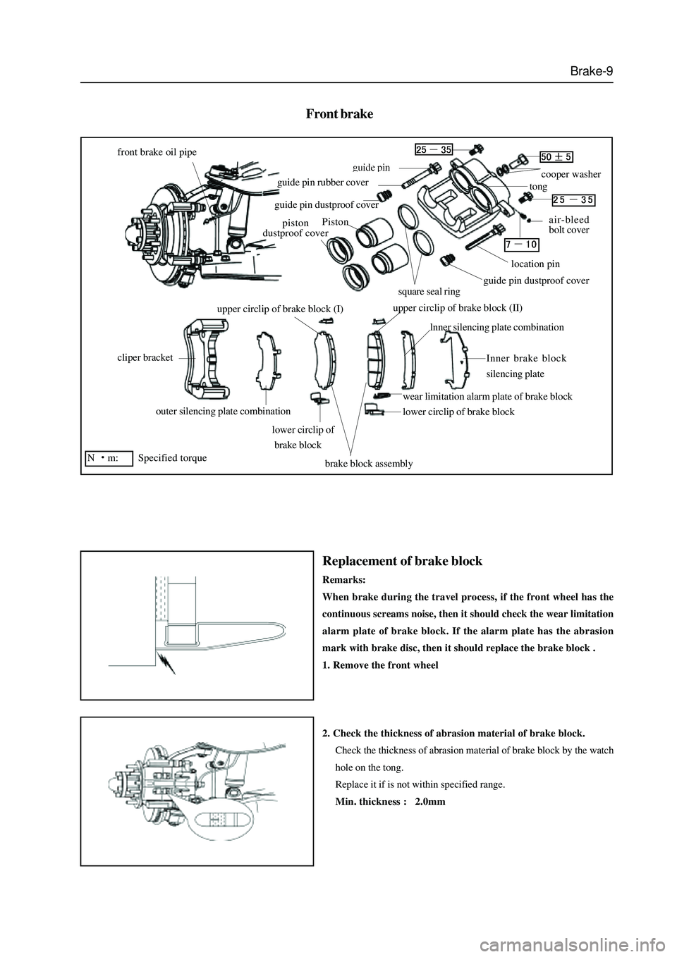
Front brake
front brake oil pipe
cliper bracket
outer silencing plate combination
lower circlip of
brake block
brake block assembly
lower circlip of brake block
wear limitation alarm plate of brake block
lnner silencing plate combination
Inner brake block
silencing plate
upper circlip of brake block (I)upper circlip of brake block (II)
piston
dustproof cover
guide pin dustproof cover
guide pin rubber covercooper washer
tong
air-bleed
bolt cover
location pin
guide pin dustproof coversquare seal ring
N
m: Specified torque
Piston
Replacement of brake block
Remarks:
When brake during the travel process, if the front wheel has the
continuous screams noise, then it should check the wear limitation
alarm plate of brake block. If the alarm plate has the abrasion
mark with brake disc, then it should replace the brake block .
1. Remove the front wheel
2. Check the thickness of abrasion material of brake block.
Check the thickness of abrasion material of brake block by the watch
hole on the tong.
Replace it if is not within specified range.
Min. thickness : 2.0mm
Page 302 of 425

Brake-16
Rear brake (Disk-and-drum type)
tong bracket
pin rubber cover
brake caliper locking bolt 100
silencing plate
combination
outside brake block
inside brake block
brake block wearing
indication plate
cylinder hole
dustproof cover
wire clip
rectangle seal ring
piston
tong body (left)
copper washer
brake oil pipe fastening blot 55
location pin 2530
bleed screw
bleed screw dustproof cover
guide pin 2530
rear brake oil pipeline
N
m: specified torque
peepholesilencing
plate
Replacement of brake block
Remarks: if the rear wheel generates the cheep during the braking,
it should check the abrasion indication plate of brake block. If the
indication plate has the abrasion mark with brake disc, then it
should replace the brake block .
1. Remove the rear wheel
2. Check the thickness of brake block bush.
Measure the thickness of the brake block bush (abrasion material)
from the eyehole of tong. If the thickness is not within the specified
range, then it should replace the brake block.
minimum thickness: 2.0mm.
Page 324 of 425

Steering-5
Technical requirements
1.The fastening torque of the mounting bolts of the integral power
steering gear assembly is
2.The fastening torque of the connecting bolts of the steering drive sub-
assembly and the integral power steering gear assembly is
3. The fastening torque of the connecting bolts of the steering drive
assembly and the left horizontal beam of the frame is
4. The fastening torque of the mounting bolts of the power steering
pump is 40N.m.
5. The tension force of multi-wedge belt 4PK1100 is 4PK1100.
6. Centering fastening of the handwheel: steer the front wheel to the
right front and remove the handwheel without changing the position
of the steering stem, install the handwheel aligning the center, the
radials of the handwheel should be at the left & right centering state;
the symbol of “the Great Wall” on the steering wheel shall be in
driver’s straight view position, secure the nut firmly with the
fastening torque of
7. Inspection of free clearance of the handwheel
Steer the car in a straight direction and stop the engine, apply a 5N force to
the handwheel along the circumference, left turn the handwheel and stop
the turning when the resistance is increasingly felt with each turn; then right
turn the handwheel and stop the turning when the resistance is increasingly
felt with each turn; the angle rotated along the circumference is the free
clearance of the handwheel, whose standard value shall be below 20
, and
the angle from the center to the right shall not be more than 10