Page 28 of 425
Exhaust system
N.m Specific torque
Used component which can not be used any more.
end washer assembly
exhaust pipe outlet nut
front section of exhaust pipe
hexagon flange nut
cleaner cushion
assembly 1
fastening bolt of hoop
cleaner heat insulation cover clip
cleaner discharge pipe catalytic converter
three-hole rubber block
cleaner cushion assembly 2
hexagon flange nut
muffler assembly
muffler port decoration cover
hexagon flange nut
rear section assembly
of exhaust pipe
wahser assembly
100
9
63
5
23muffler damping
ruber block assembly
Page 34 of 425
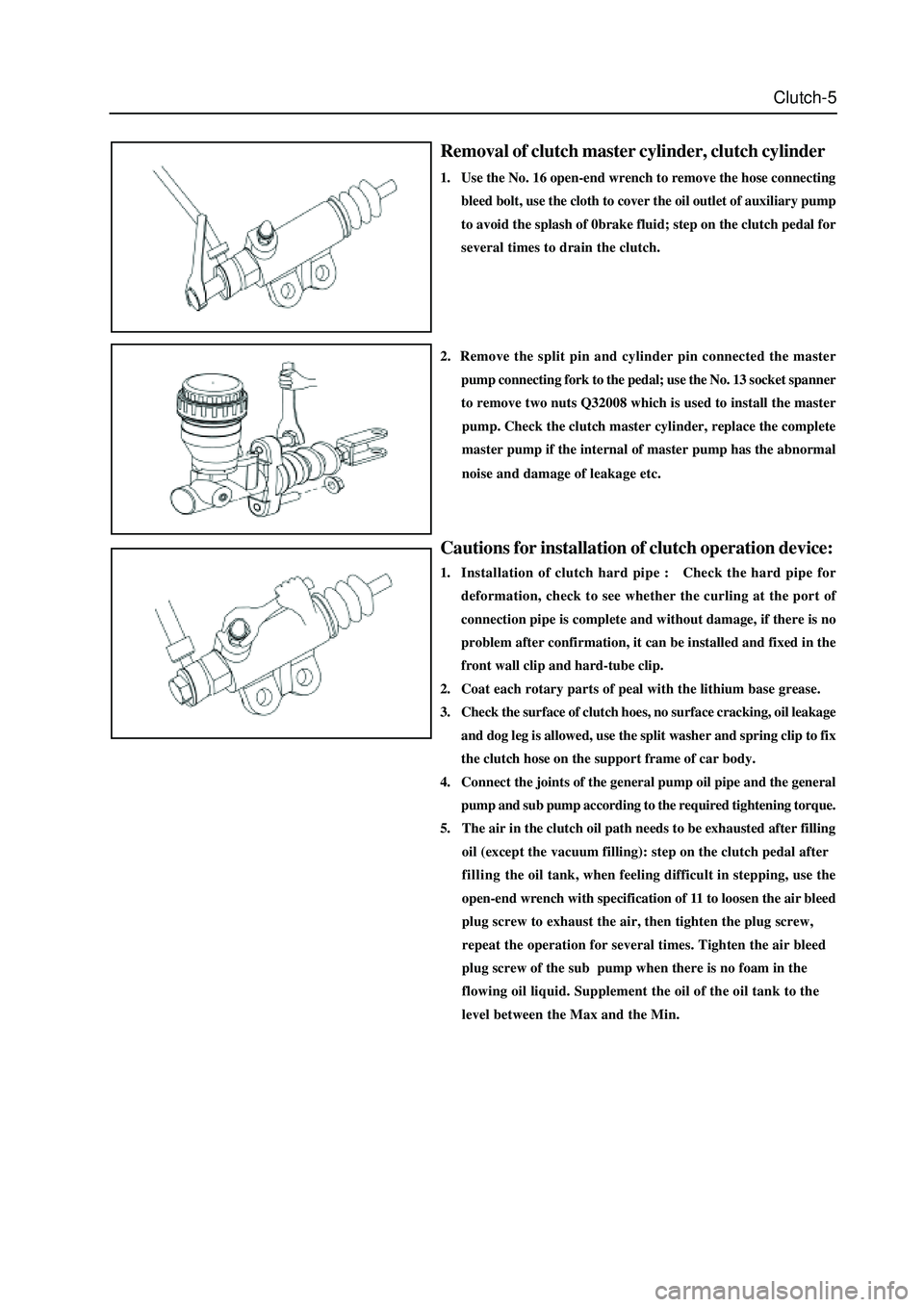
Clutch-4
Cluch control mechanism
clutch master cylinder
N
m: specified torque
Page 35 of 425

Clutch-5
Removal of clutch master cylinder, clutch cylinder
1. Use the No. 16 open-end wrench to remove the hose connecting
bleed bolt, use the cloth to cover the oil outlet of auxiliary pump
to avoid the splash of 0brake fluid; step on the clutch pedal for
several times to drain the clutch.
Cautions for installation of clutch operation device:
1. Installation of clutch hard pipe : Check the hard pipe for
deformation, check to see whether the curling at the port of
connection pipe is complete and without damage, if there is no
problem after confirmation, it can be installed and fixed in the
front wall clip and hard-tube clip.
2. Coat each rotary parts of peal with the lithium base grease.
3. Check the surface of clutch hoes, no surface cracking, oil leakage
and dog leg is allowed, use the split washer and spring clip to fix
the clutch hose on the support frame of car body.
4. Connect the joints of the general pump oil pipe and the general
2. Remove the split pin and cylinder pin connected the master
pump connecting fork to the pedal; use the No. 13 socket spanner
to remove two nuts Q32008 which is used to install the master
pump. Check the clutch master cylinder, replace the complete
master pump if the internal of master pump has the abnormal
noise and damage of leakage etc.
pump and sub pump according to the required tightening torque.
5. The air in the clutch oil path needs to be exhausted after filling
oil (except the vacuum filling): step on the clutch pedal after
fillingthe oil tank, when feeling difficult in stepping, use the
open-end wrench with specification of 11 to loosen the air bleed
plug screw to exhaust the air, then tighten the plug screw,
repeat the operation for several times. Tighten the air bleed
plug screw of the sub pump when there is no foam in the
flowing oil liquid. Supplement the oil of the oil tank to the
level between the Max and the Min.
Page 36 of 425

Clutch-6
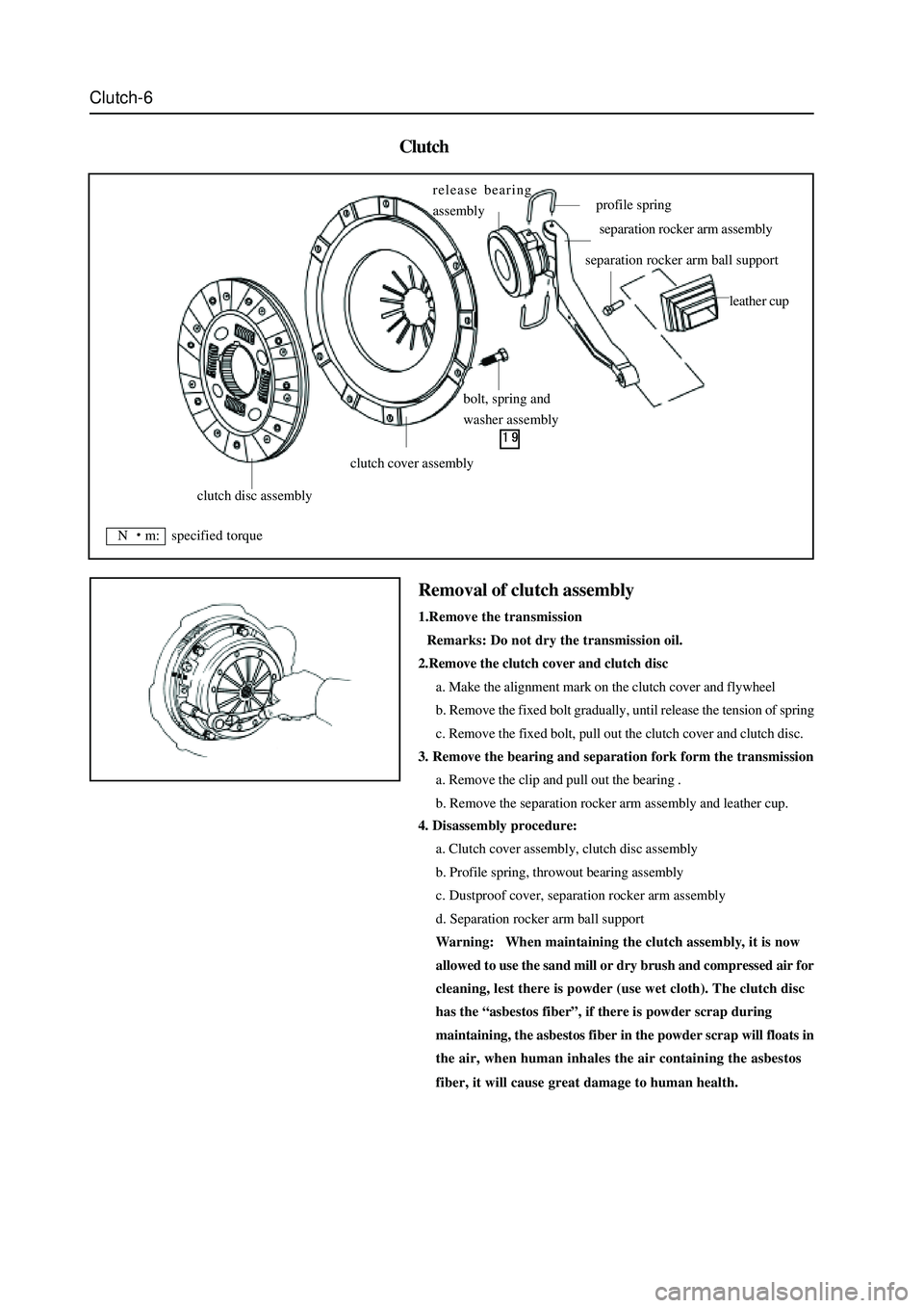
Clutch
4. Disassembly procedure:
a. Clutch cover assembly, clutch disc assembly
b. Profile spring, throwout bearing assembly
c. Dustproof cover, separation rocker arm assembly
d. Separation rocker arm ball support
Warning: When maintaining the clutch assembly, it is now
allowed to use the sand mill or dry brush and compressed air for
cleaning, lest there is powder (use wet cloth). The clutch disc
has the “asbestos fiber”, if there is powder scrap during
maintaining, the asbestos fiber in the powder scrap will floats in
the air, when human inhales the air containing the asbestos
fiber, it will cause great damage to human health.
Removal of clutch assembly
1.Remove the transmission
Remarks: Do not dry the transmission oil.
2.Remove the clutch cover and clutch disc
a. Make the alignment mark on the clutch cover and flywheel
b. Remove the fixed bolt gradually, until release the tension of spring
c. Remove the fixed bolt, pull out the clutch cover and clutch disc.
3. Remove the bearing and separation fork form the transmission
a. Remove the clip and pull out the bearing .
b. Remove the separation rocker arm assembly and leather cup.
clutch disc assembly
clutch cover assembly
bolt, spring and
washer assembly release bearing
assembly
profile spring
separation rocker arm assembly
separation rocker arm ball support
leather cup
N m: specified torque
Page 43 of 425

Inspection of SC5M2D-C transmission:
1.Check the oil level of transmission:
Screw off the oil discharge plug of the transmission; discharge all lubri-
cate oil; screw on the oil discharge plug to the specified torque; the
torque is: 30
35Nm. Fill the transmission with the transmission
oil through the oil filling port, oil number is hyperbolic gear oil SAE80W/
90, which meet API GL-4, oil capacity are 2.2L. Tighten the oil-filling
plug to the specified torque of 30
35Nm. (for area with high or
low temperature refer to the maintenance specification)
2. Replacement of oil seal of rear hosing:
The replacement of the oil seal of rear housing is shown in figure.
Disconnect the drive shaft from the rear housing; remove the oil seal
by the flat screwdriver, then use the special tools to knock the rear
housing oil seal in the rear housing. It should pay attention to the
installation of oil seal, shown as figure. Coat the lip of oil seal with the
specified transmission oil.
3. Removal, installation and inspection of transmission
The preoperation before removal and after installation of transmission
is: Remove and install the manipulator cover assembly, drain and fill
the transmission oil accordance with the regulation; after remove and
install the drive shaft. Separate each plug-in part from the vehicle
transmission .
4
Inspection of manipulator cover assembly
Shown as figure, remove the adhesive on the surface before installation,
use the screwdriver( M8
1.25) to clean the adhesive in the screw
hole; coat the installed part of bolt screw with the specified screw
adhesive. Firstly, install two positioning bolts A, then install other
two bolt A and bolt C respectively. The tightening torque of all bolts is
15
22Nm.
oil filling screw plug (SC1701005)
oil-drain screw-plug assembly (JK721701071)
rear housing oil seal
bolt C(SC-1704003)bolt A(SC-1704004)
Page 44 of 425
SC5M2D-C transmission assembly
handle of gearlever
dustproof seal cover
oil seal 39.65210
odometer driven gear assembly
odometer seating lock plate
cylindrical compression spring
1.05.841
bush
select & shift seating
N m: specified torque
Used component which can not be used any more.
Pregummed component
Use the special toolsmanipulator cover assembly
elastic cylindrical pin 6
22
rear housing assembly spring cylindrical pin
reverse lamp switch bracket
bearing housing assembly
clutch housing assembly
location compression
cylindrical pin
Page 45 of 425
Disassembly of transmission (SC5M2D-C)
1.Remove the hexagon bolt M818 and lock plate.
Caution: The tightening torque is 14-19N
m when install the
hexagon bolt;
2.Remove the odometer driven gear assembly
Use the special tools to remove the odometer driven gear assembly
3.Remove the rear housing assembly
a. Remove 6 M10
1.2530 hexagon bolts
Caution: The tightening torque is 14-19N
m when installs 6
M10
1.2530 hexagon bolts.
b. Use the rubber hammer to knock the rear housing and take out the
rear housing assembly.
4. Remove 2 location pins and bushes.
Page 46 of 425
Manipulator cover assembly
gearbox assembly (one)
reverse lock assembly nut M8
bulbrubber cover
pin 740
master control lever assembly
bulb basebush
stop plate of main rodbush
bulb jacket
N m: specified torque
Used component which can not be used any more.
Pregummed component N
m: specified torque
Used component which can not be used any more.
bush
6
oil guiding plate
location pin
steel ball 7.
938
aluminum gasket
reverse lamp switch
gearbox
selection and shifting
shaft rubber choke plug
bleed plug assembly
bush
selection and shifting block
elastic cylindrical pin 622