Page 135 of 425

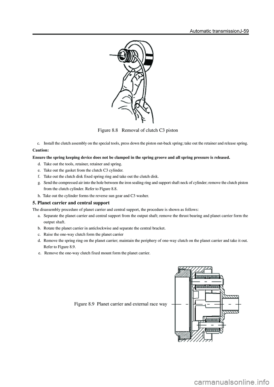
Figure 8.8 Removal of clutch C3 piston
c. Install the clutch assembly on the special tools, press down the piston out-back spring; take out the retainer and release spring.
Caution:
Ensure the spring keeping device does not be clamped in the spring groove and all spring pressure is released.
d. Take out the tools, retainer, retainer and spring.
e. Take out the gasket from the clutch C3 cylinder.
f. Take out the clutch disk fixed spring ring and take out the clutch disk.
g. Send the compressed air into the hole between the iron sealing ring and support shaft neck of cylinder; remove the clutch piston
from the clutch cylinder. Refer to Figure 8.8.
h. Take out the cylinder forms the reverse sun gear and C3 washer.
5. Planet carrier and central support
The disassembly procedure of planet carrier and central support, the procedure is shown as follows:
a. Separate the planet carrier and central support from the output shaft; remove the thrust bearing and planet carrier form the
output shaft.
b. Rotate the planet carrier in anticlockwise and separate the central bracket.
c. Raise the one-way clutch form the planet carrier
d. Remove the spring ring on the planet carrier; maintain the periphery of one-way clutch on the planet carrier and take it out.
Refer to Figure 8.9.
e. Remove the one-way clutch fixed mount form the planet carrier.
Figure 8.9 Planet carrier and external race way
Page 142 of 425

connecting housing (4WD)connecting housing
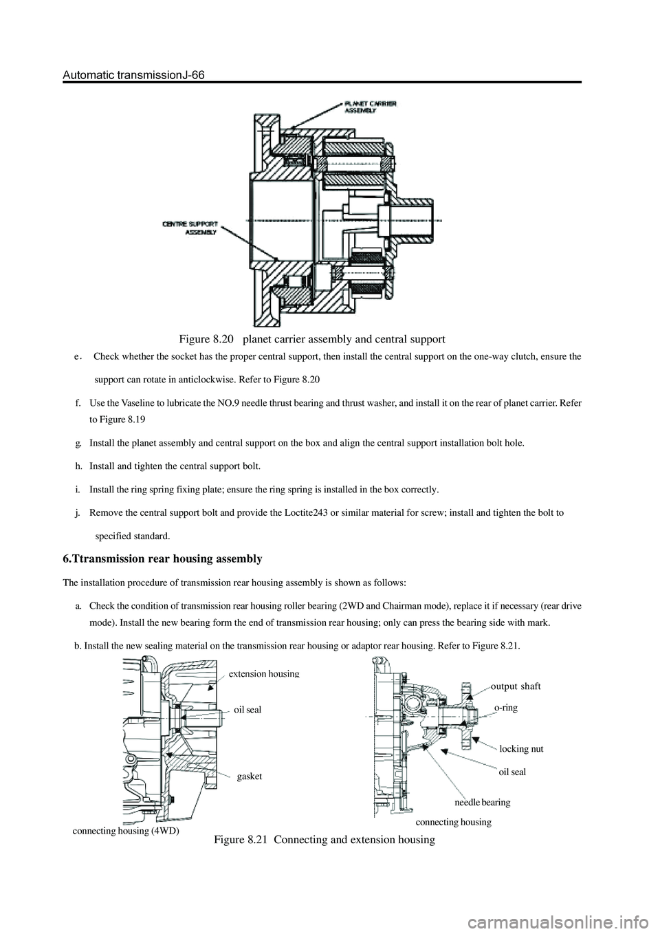
Figure 8.20 planet carrier assembly and central support
eCheck whether the socket has the proper central support, then install the central support on the one-way clutch, ensure the
support can rotate in anticlockwise. Refer to Figure 8.20
f. Use the Vaseline to lubricate the NO.9 needle thrust bearing and thrust washer, and install it on the rear of planet carrier. Refer
to Figure 8.19
g. Install the planet assembly and central support on the box and align the central support installation bolt hole.
h. Install and tighten the central support bolt.
i. Install the ring spring fixing plate; ensure the ring spring is installed in the box correctly.
j. Remove the central support bolt and provide the Loctite243 or similar material for screw; install and tighten the bolt to
specified standard.
6.Ttransmission rear housing assembly
The installation procedure of transmission rear housing assembly is shown as follows:
a. Check the condition of transmission rear housing roller bearing (2WD and Chairman mode), replace it if necessary (rear drive
mode). Install the new bearing form the end of transmission rear housing; only can press the bearing side with mark.
b. Install the new sealing material on the transmission rear housing or adaptor rear housing. Refer to Figure 8.21.
Figure 8.21 Connecting and extension housing
output shaft
o-ring
locking nut
oil seal
needle bearing oil seal
gasket
Page 147 of 425

v. Install the thrust disc on the cylinder internal wheel axle. Refer to Figure 8.24and 8.19.
w. Connect the C2 /clutch C4 wheel axle assembly in clutch C4 disc, install the clutch C2 disc. Install the C3 wheel axle and
reinforce it by ring spring; ensure the ring spring is installed in the groove fixedly. Please refer to Figure 8.24.
10. Clutch C3 and reverse central gear system
The assembly procedure of clutch C3 and reverse central gear assembly (refer to Figure 8.28) is shown as follows:
Check the cleanness of hole on cylinder. Caution:
It should take out the clutch clearance assembly before immerse the assembly into the automatic transmission fluid
(ATF).
s. Use the gear selection plate to reach the correct specification. It should remove the clutch assembly and immerse the friction
disk in the automatic transmission fluid for 5 minutes at least before the installation if install the new friction disks. Lubricate
and install the 3-4 one-way clutch and install the sleeve on the C2 wheel axle. Adjust the handle rear and install the nylon thrust
washer on the C4 wheel axle. Refer to Figure 8.27.
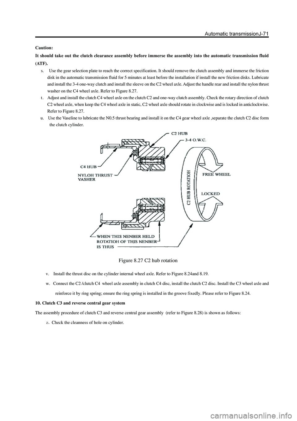
t . Adjust and install the clutch C4 wheel axle on the clutch C2 and one-way clutch assembly. Check the rotary direction of clutch
C2 wheel axle, when keep the C4 wheel axle in static, C2 wheel axle should rotate in clockwise and is locked in anticlockwise.
Refer to Figure 8.27.
u. Use the Vaseline to lubricate the N0.5 thrust bearing and install it on the C4 gear wheel axle ,separate the clutch C2 disc form
the clutch cylinder.
Figure 8.27 C2 hub rotation
Page 236 of 425
5. Remove the drive gear flange and dustproof cover
assembly
a. Use the hand hammer and chisel to loose the riveted part on
nut.
b. Use the special tools to clamp the drive gear flangeandremove
the drive gear nut.
c. Use the cooper bar to knock down the drive gear flange and
dustproof cover assembly.
6. Remove the drive gear oil seal
Use the special tools to remove the oil seal; do not
damage the inner wall of reducer housing.
7. Install the new drive gear oil seal
a. Use the special tools to knock into the new oil seal.
b. The top of the oil seal is level to the top of reducer housing.
Caution: Coat the oil seal lip with the lithium base grease and
the oil seal should be in correct position.
special
rotate the wrench in clockwise.
specialspecial
Page 251 of 425
15. Use the wrench to remove the bolt fixed the
clump weight bracket welded assembly.
16. Use the wrench to remove the bolt and nut used
to fix the front reducer assembly and front axle
housing.
17. Use the brass rod or hand hammer to knock the
front reducer housing to separate it from the front
drive axle housing.
18. Check the run-out of driven bevel gear.
Rotate the flange; use the dial indicator to measure
the run-out of driven bel gear.
Max. Runout: 0.07mm
It should replace the drive and driven bevel gear totally if the run-
out is more than 0.07mm.
19Check the running clearance of drive and
driven bevel gear.
a. Install the dial indicator and ensure the side axis is vertical to
contact tooth surface.
b. Hold the drive gear flange and rotate the driven bevel gear in
clockwise and anticlockwise to measure the clearance.
Specified range of clearance: 0.15-0.25mm
Remarks: Check three average points on circumference of driven
bevel gear at least.
Page 253 of 425
25. Use the special tools to remove the small
bearing inner race, and then reverse the reducer
to slide out the spacer.
Remarks: The bearing should be replaced by new
one if damaged.
26. Use the wrench to remove two bearing glands.
Remarks: It should distinguish the left and right of
the bearing gland when remove it to avoid the
confusion.
Remove the side bearing outer race and marked
with L and R.
29. Remove the left and right adjusting washer; mea-
sure its thickness; marked with left and right. 27. Use the brass rod to vibrate the differential
assembly upwardly, then take out the differential
assembly.
holding
pliers
special tools
rotate the wrench in clockwise
24. Use the special tools to remove the drive gear oil
seal.
Page 261 of 425
19. Use the torque measuring meter to measure the
total pre-applied load of front reducer.
specified torque : 1.8-2.4Nm
sound contactlarge end contact
toe contact
select the adjusting washer which can make the drive gear close to the
driven bevel gear
select the adjusting washer which can make the drive
gear away form the driven bevel gear rsmall end contact
dedendum contact
20. Check the meshing mark of drive and driven
bevel gear.
a. Paint 3-4 teeth with the red lead in three different positions
of driven bevel gear.
b. Hold the flange of drive gear; rotate the driven bevel gear in
clockwise and anticlockwise.
c. Check the contacting condition of gear tooth.If the meshing
mark of drive and driven bevel gear does not consist with
thatshown in figure, it should select the proper adjusting
washer for modification according to the detailed form of
meshing mark.
convex of drivenconcave of driven bevel
Page 279 of 425
b. Adhere the measuring meter base on the end surface of reducer
housing; the measuring head contacts the tooth surface; rotate
the driven gear by hand and measure the engagement clearance be
tween the drive and driven gear.
c. If the engagement clearance does not meet the requirement, use
the special tools to adjust the left and right adjusting ring until it
meets the requirement.
d. Recheck the engagement clearance between the drive and driven
gear.
Engagement clearance: 0.13-0.18mm
14. Check the meshing mark of drive and driven bevel
gear.
a. Paint 3-4 teeth with the red lead in three different positions of
driven bevel gear.
b. Rotate the driven bevel gear in clockwise and anticlockwise by
hand.Check the engagement of gear.