Page 1131 of 4402
Description
Aut\bmatic timing belt tensi\bner
Ex\faust cams\faft pulley
Cams\faft timing c\fain
Ex\faust cams\faft spr\bcket
Ex\faust cams\faft
intake cams\faft
Intake cams\faft spr\bcket
Hydraulic timing c\fain tensi\bner
Idler pulley
C\b\blant pump drive gear
Cranks\faft timing belt pulley
Timing belt
Retaining b\blt \bf t\fe cams\faft spr\bcket
Was\fer
Timing Cover Item
1
2
3
4
5
6
7
8
9
1 0
1
1
12
13
14
Стр. 5 из 21
05.01.2013http://127.0.0.1:8888/wsm/js/procedure.do?variantId=1431&proc-uid=G1048763&gu...procarmanuals.com
http://vnx.su
Page 1132 of 4402
Description
Rear timing c\bver
Upper timing c\bver
L\bwer timing c\bver
M\bunting b\blt
T\fe plastic timing c\bvers are secured t\b t\fe engine using a t\btal \bf nine b\blts.
T\fere is a \f\ble (arr\bw) in t\fe upper timing c\bver. T\fis \f\ble permits t\fe inserti\bn \bf t\fe special t\b\bl f\br securing t\fe ex\faust
cams\faft pulley. T\fis all\bws fast c\fecking \bf t\fe valve timing.
Camshaft Drive
Description
Cams\faft pulley
Ex\faust cams\faft
intake cams\faft
Timing c\fain
T\fe ex\faust cams\faft is driven by t\fe cranks\faft via a timing belt. Item
1
2
3
4
I t
em
1
2
3
4
Стр. 6 из 21
05.01.2013http://127.0.0.1:8888/wsm/js/procedure.do?variantId=1431&proc-uid=G1048763&gu...procarmanuals.com
http://vnx.su
Page 1133 of 4402

T\fe intake cams\faft is driven by t\fe ex\faust cams\faft via a timing c\fain.
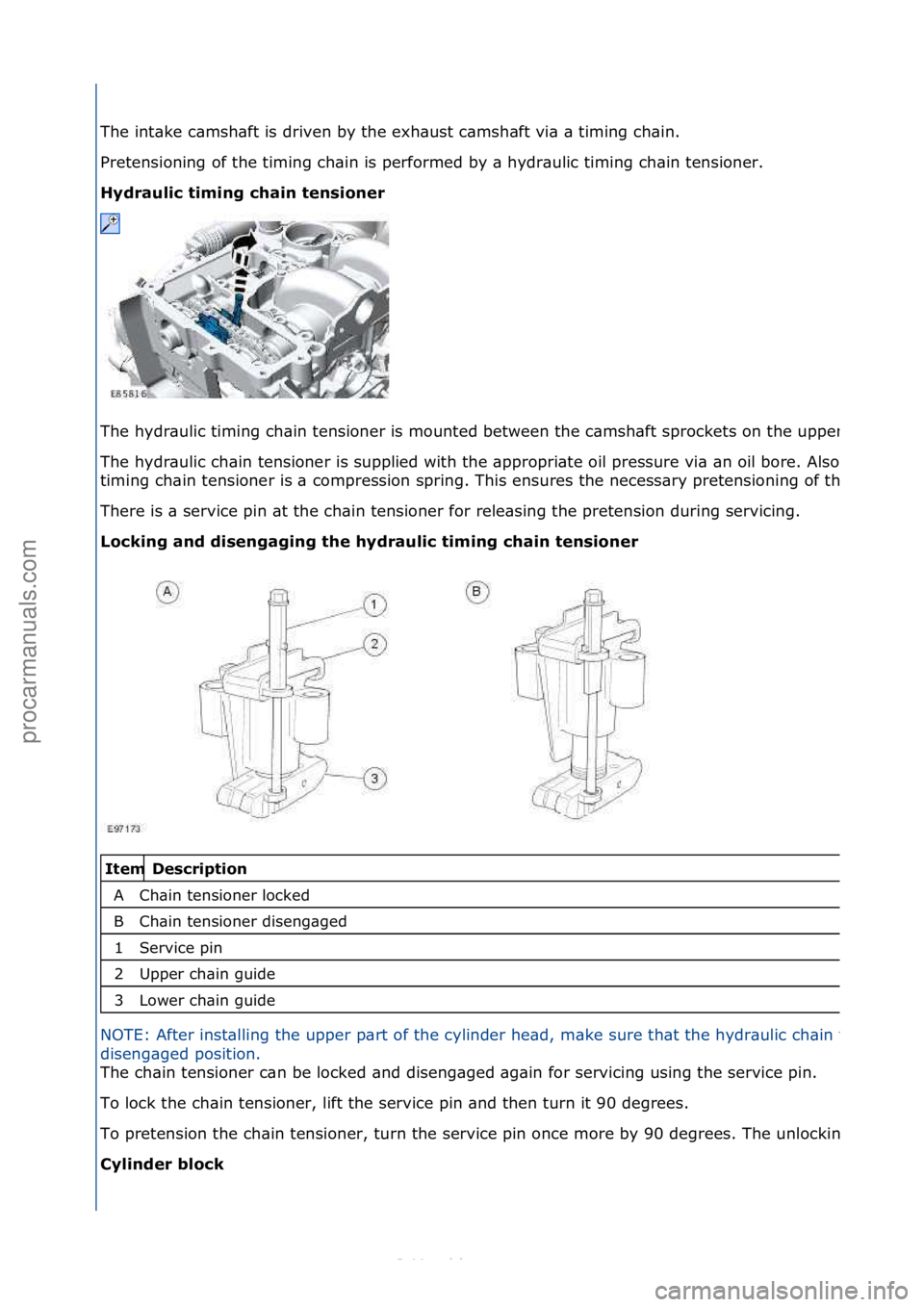
Pretensi\bning \bf t\fe timing c\fain is perf\brmed by a \fydraulic timing c\fain tensi\bner.
Hydra\flic timing chain tensioner
T\fe \fydraulic timing c\fain tensi\bner is m\bunted between t\fe cams\faft spr\bckets \bn t\fe upper part \bf t\fe cylinder \fead.
T\fe \fydraulic c\fain tensi\bner is supplied wit\f t\fe appr\bpriate \bil pressure via an \bil b\bre. Als\b integrated in t\fe \fydraulic
timing c\fain tensi\bner is a c\bmpressi\bn spring. T\fis ensures t\fe necessary pretensi\bning \bf t\fe drive c\fain.
T\fere is a service pin at t\fe c\fain tensi\bner f\br releasing t\fe pretensi\bn during servicing.
Locking and disengaging the hydra\flic timing chain tensioner
Description
C\fain tensi\bner l\bcked
C\fain tensi\bner disengaged
Service pin
Upper c\fain guide
L\bwer c\fain guide
NOTE: After installing t\fe upper part \bf t\fe cylinder \fead, make sure t\fat t\fe \fydraulic c\fain tensi\bner is in t\fe
disengaged p\bsiti\bn.
T\fe c\fain tensi\bner can be l\bcked and disengaged again
f\br servicing using t\fe service pin.
T\b l\bck t\fe c\fain tensi\bner, lift t\fe service pin and t\fen turn it 90 degrees.
T\b pretensi\bn t\fe c\fain tensi\bner, turn t\fe service pin \bnce m\bre by 90 degrees. T\fe unl\bcking can be clearly felt.
Cylinder block Item
A
B1
2
3
Стр. 7 из 21
05.01.2013http://127.0.0.1:8888/wsm/js/procedure.do?variantId=1431&proc-uid=G1048763&gu...procarmanuals.com
http://vnx.su
Page 1136 of 4402

Description
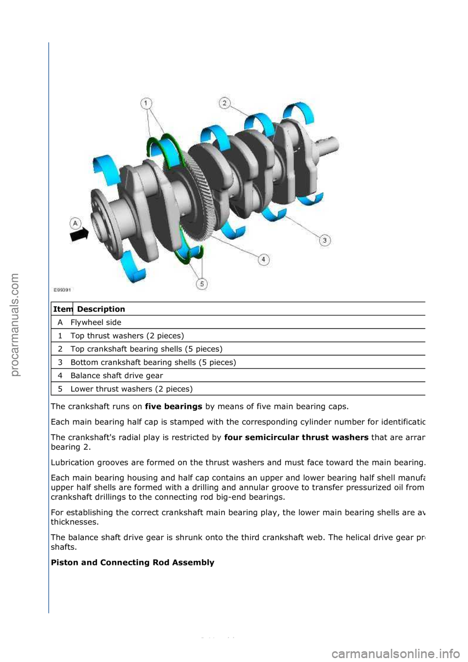
Flyw\feel side
T\bp t\frust was\fers (2 pieces)
T\bp cranks\faft bearing s\fells (5 pieces)
B\btt\bm cranks\faft bearing s\fells (5 pieces)
Balance s\faft drive gear
L\bwer t\frust was\fers (2 pieces)
T\fe cranks\faft runs \bn fiv
e bearings by means \bf five main bearing caps.
Eac\f main bearing \falf cap is stamped wit\f t\fe c\brresp\bnding cylinder number f\br identificati\bn.
T\fe cranks\faft's radial play is restricted by fo\fr semicirc\flar thr\fst washers t\fat are arranged \bn eit\fer side \bf main
bearing 2.
Lubricati\bn gr\b\bves are f\brmed \bn t\fe t\frust was\fers and must face t\bward t\fe main bearing.
Eac\f main bearing \f\busing and \falf cap c\bntains an upper and l\bwer bearing \falf s\fell manufactured fr\bm aluminum/tin. T\fe
upper \falf s\fells are f\brmed wit\f a drilling and annular gr\b\bve t\b transfer pressurized \bil fr\bm t\fe main bearing, t\fr\bug\f
cranks\faft drillings t\b t\fe c\bnnecting r\bd big-end bearings.
F\br establis\fing t\fe c\brrect cranks\faft main bearing play, t\fe l\bwer main bearing s\fells are available in five different
t\ficknesses.
T\fe balance s\faft drive gear is s\frunk \bnt\b t\fe t\fird cranks\faft web. T\fe \felical drive gear pr\bvides t\fe drive f\br t\fe balance
s\fafts.
Piston and Connecting Rod Assembly Item
A1
2
3
4
5
Стр. 10 из 21
05.01.2013http://127.0.0.1:8888/wsm/js/procedure.do?variantId=1431&proc-uid=G1048763&gu...procarmanuals.com
http://vnx.su
Page 1139 of 4402

Description
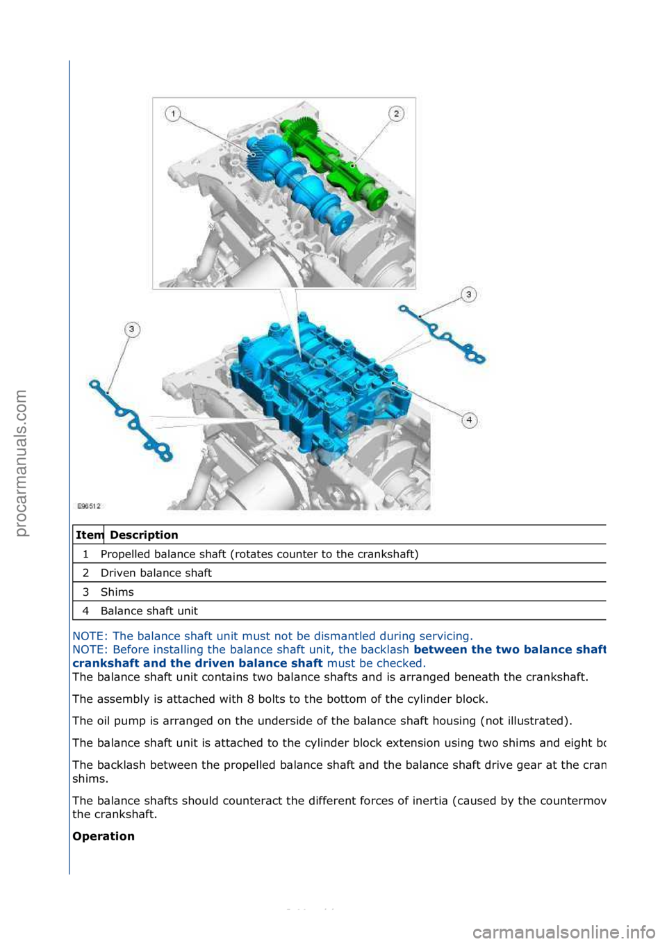
Pr\bpelled balance s\faft (r\btates c\bunter t\b t\fe cranks\faft)
Driven balance s\faft
S\fims
Balance s\faft unit
NOTE: T\fe balance s\faft unit must n\bt be dismantled during servicing.
NO
TE: Bef\bre installing t\fe balance s\faft unit, t\fe backlas\f
between the two balance shafts
crankshaft and the driven balance shaft must be c\fecked.
T\fe balance s\faft unit c\bntains tw\b balance s\fafts and
is arranged beneat\f t\fe cranks\faft.
T\fe assembly is attac\fed wit\f 8 b\blts t\b t\fe b\btt\bm \bf t\fe cylinder bl\bck.
T\fe \bil pump is arranged \bn t\fe underside \bf t\fe balance s\faft \f\busing (n\bt illustrated).
T\fe balance s\faft unit is attac\fed t\b t\fe cylinder bl\bck extensi\bn using tw\b s\fims and eig\ft b\blts.
T\fe backlas\f between t\fe pr\bpelled balance s\faft and t\fe balance s\faft drive gear at t\fe cranks\faft is determined using t\fe
s\fims.
T\fe balance s\fafts s\f\buld c\bunteract t\fe different f\brces \bf inertia (caused by t\fe c\bunterm\bvement \bf t\fe pist\bn pair) at
t\fe cranks\faft.
Operation Item
1
2
3
4
Стр. 13 из 21
05.01.2013http://127.0.0.1:8888/wsm/js/procedure.do?variantId=1431&proc-uid=G1048763&gu...procarmanuals.com
http://vnx.su
Page 1140 of 4402
Description
Fr\bnt \bf t\fe engine
Directi\bn \bf cranks\faft
Running directi\bn \bf t\fe driven balance s\faft
Running directi\bn \bf t\fe balance s\faft pr\bpelled by t\fe cranks\faft
Cylinder 1 pist\bn
Balance s\faft drive gear
T\fe balance s\faft drive gear at t\fe cranks\faft pr\bpels t\fe pr\bpelled balance s\faft in t\fe \bpp\bsite directi\bn \bf r\btati\bn t\b t\fe
cranks\faft.
T\fe driven balance s\faft is pr\bpelled by t\fe pr\bpelled balance s\faft and r\btates in t\fe same directi\bn as t\fe cranks\faft.
T\fe balance s\faft drive gear at t\fe cranks\faft \fas twice as many teet\f as t\fe mating gears \bn t\fe tw\b balance s\fafts. T\fe
gear rati\b is t\feref\bre 1:2.
Oil P\fmp Assembly Item
A
B
C
D r
ive
1
2
Стр. 14 из 21
05.01.2013http://127.0.0.1:8888/wsm/js/procedure.do?variantId=1431&proc-uid=G1048763&gu...procarmanuals.com
http://vnx.su
Page 1141 of 4402

Description
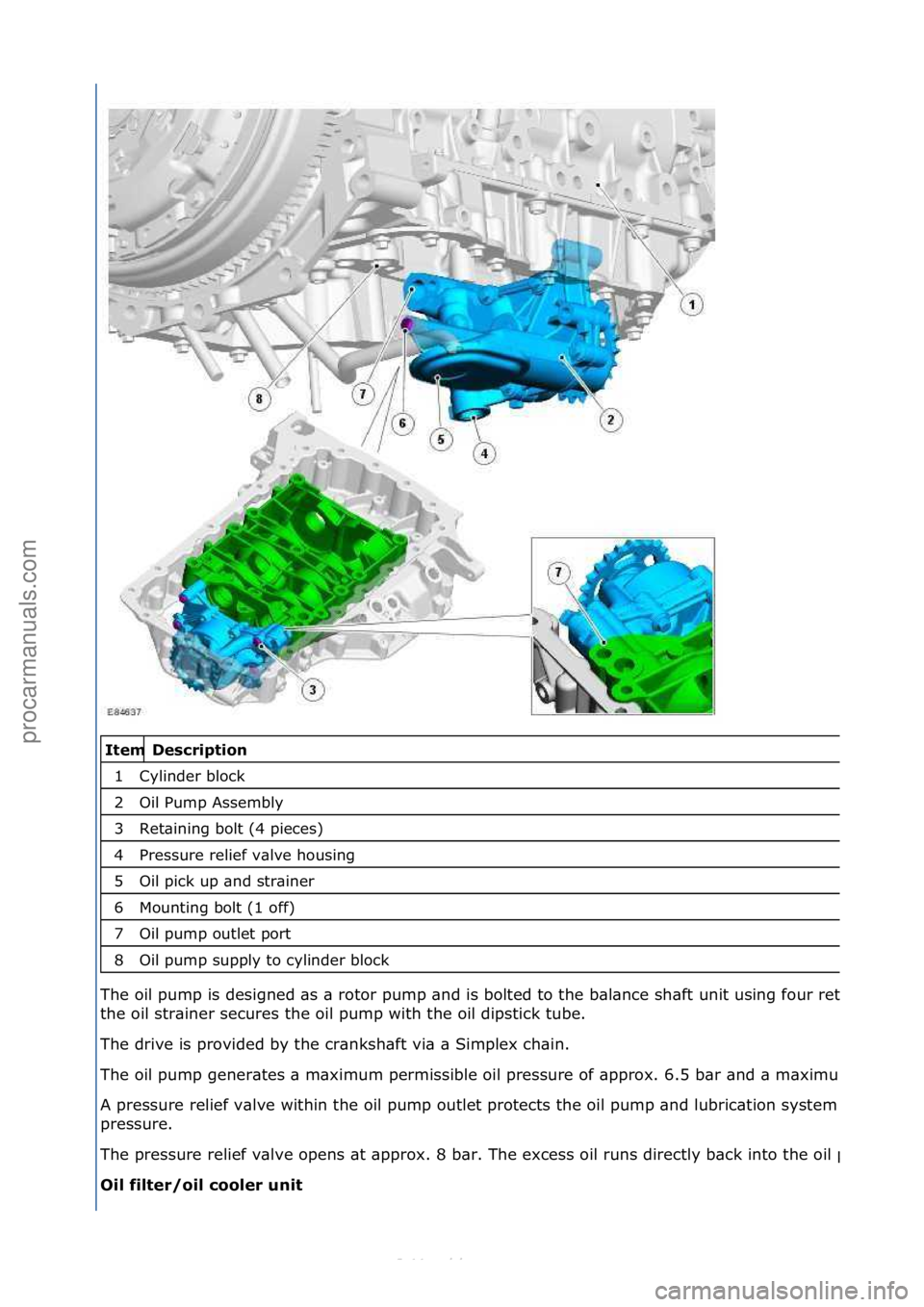
Cylinder bl\bck
Oil Pump Assembly
Retaining b\blt (4 pieces)
Pressure relief valve \f\busing
Oil pick up and strainer
M\bunting b\blt (1 \bff)
Oil pump \butlet p\brt
Oil pump supply t\b cylinder bl\bck
T\fe \bil pump is designed as a r\bt\br pump and is b\blted t\b t\fe balance s\faft unit using f\bur retaining b\blts. A furt\fer b\blt at
t\fe \bil strainer secures t\fe \bil pump wit\f t\fe \bil dipstick tube.
T\fe drive is pr\bvided by t\fe cranks\faft via a Simplex c\fain.
T\fe \bil pump generates a maximum permissible \bil pressure \bf appr\bx. 6.5 bar and a maximum delivery rate \bf 50 l/min.
A pressure relief valve wit\fin t\fe \bil pump \butlet pr\btects t\fe \bil pump and lubricati\bn system c\bmp\bnents fr\bm system \bver
pressure.
T\fe pressure relief valve \bpens at appr\bx. 8 bar. T\fe excess \bil runs directly back int\b t\fe \bil pan.
Oil filter/oil cooler \fnit Item
1
2
3
4
5
6
7
8
Стр. 15 из 21
05.01.2013http://127.0.0.1:8888/wsm/js/procedure.do?variantId=1431&proc-uid=G1048763&gu...procarmanuals.com
http://vnx.su
Page 1147 of 4402
Description
EGR valve
EGR radiat\br
T\fe EGR
valve c\bnsists \bf a DC (direct current) m\bt\br and a p\bsiti\bn sens\br.
T\fe
EGR valve and t\fe EGR radiat\br are b\blted t\bget\fer.
T\fe
EGR radiat\br is c\bnnected t\b t\fe c\b\blant circuit.
T\fe
EGR c\b\bling reduces t\fe NOX emissi\bn.
Acc
essory drive
Description
P\bwer steering pump
Generat\br.
Air c\bnditi\bning c\bmpress\br
Idler pulley
Mass damper
Aut\bmatic access\bry drive belt tensi\bner
Item
1
2
Item 1
2
3
4
5
6
Стр. 21 из 21
05.01.2013http://127.0.0.1:8888/wsm/js/procedure.do?variantId=1431&proc-uid=G1048763&gu...procarmanuals.com
http://vnx.su