Page 193 of 274
192
WARNING
LIGHTS AND
MESSAGES
CAR
MAINTENANCE
TECHNICAL
SPECIFICATIONS
IINDEX
DASHBOARD
AND CONTROLS
SAFETY
DEVICES
CORRECT USE
OF THE CAR
IN AN
EMERGENCY
IF AN INTERIOR LIGHT
BURNS OUT
For the type of bulb and power rating, see
“When needing to change a bulb”.
FRONT CEILING LIGHT
Versions without Skywindow
sunroof
To change the bulb, proceed as follows:
❒press the catches A-fig. 41and with-
draw the plastic cover B;
❒slacken the 2 fastening screws A-
fig. 42, then turn the 2 bulb holders B
counterclockwise;
❒remove the bulbs and replace them. To
replace bulb C-fig. 42, release it from
the side contacts making sure that the
new bulb is correctly clamped between
the contacts.
Versions with Skywindow sunroof
To change the bulbs, proceed as follows:
❒remove the front ceiling light A-
fig. 43pressing the plastic cover as
shown by the arrows
❒disconnect electric connectors B-
fig. 44and C;
fig. 41F0C0201m
fig. 42F0C0202m
fig. 43F0C0253m
fig. 44F0C0398m
Page 194 of 274

193
WARNING
LIGHTS AND
MESSAGES
CAR
MAINTENANCE
TECHNICAL
SPECIFICATIONS
INDEX
DASHBOARD
AND CONTROLS
SAFETY
DEVICES
CORRECT USE
OF THE CAR
IN AN
EMERGENCY
❒slacken the 2 fastening screws A-
fig. 45, then turn the 2 bulb holders B
counterclockwise, remove the bulbs
and replace them. To replace bulb C,
release it from the side contacts mak-
ing sure that the new bulb is correctly
clamped between the contacts.REAR CEILING LIGHT
(where provided)
Versions without Skywindow
sunroof
To change the bulb, proceed as follows:
❒remove the light unit A-fig. 46lever-
ing in the points shown by the arrows
(on retaining tabs);
❒replace the bulbs Breleasing them from
the side contacts making sure that the
new bulb is correctly clamped between
the contacts.Versions with Skywindow sunroof
Versions with Skywindow sunroof are fit-
ted with two rear ceiling lights.
To replace the bulbs proceed as follows:
❒using the screwdriver provided in the
kit, remove the cover A-fig. 47in the
point shown by the arrow;
❒replace the bulb B-fig. 48releasing it
from the side contacts making sure that
the new bulb is correctly clamped be-
tween the contacts.
fig. 45F0C0202m
fig. 46F0C0204m
fig. 47F0C0227mfig. 48F0C0229m
Page 195 of 274
194
WARNING
LIGHTS AND
MESSAGES
CAR
MAINTENANCE
TECHNICAL
SPECIFICATIONS
IINDEX
DASHBOARD
AND CONTROLS
SAFETY
DEVICES
CORRECT USE
OF THE CAR
IN AN
EMERGENCY
COURTESY MIRROR LIGHT
(where provided)
To change the bulb, proceed as follows:
❒open the mirror cover A-fig. 49;
❒ remove the bulb Blevering in the
points shown by the arrows;GLOVEBOX LIGHT fig. 51
To change the bulb, proceed as follows:
❒open the glovebox, then remove the
light unit A;
❒replace the bulb Breleasing it from the
side contacts making sure that the new
bulb is correctly clamped between the
contacts.
fig. 49F0C0423mfig. 50F0C0424mfig. 51F0C0205m
❒replace the bulb C-fig. 50releasing
it from the side contacts making sure
that the new bulb is correctly
clamped between the contacts.
Page 196 of 274
195
WARNING
LIGHTS AND
MESSAGES
CAR
MAINTENANCE
TECHNICAL
SPECIFICATIONS
INDEX
DASHBOARD
AND CONTROLS
SAFETY
DEVICES
CORRECT USE
OF THE CAR
IN AN
EMERGENCY
BOOT LIGHT
To change the bulb, proceed as follows:
❒open the tailgate;
❒remove the bulb A-fig. 52levering in
the points shown by the arrow.
❒open the protection B-fig. 53and re-
place the snap-fitted bulb;
❒re-close the protective cover Bon the
lens;
fig. 52F0C0221mfig. 53F0C0097mfig. 54F0C0206m
❒refit the light unit A-fig. 52inserting
it in its correct position firstly on one
end and then on the other until it clicks
into place.PUDDLE / DOOR LIGHTS fig. 54
To change the bulb, proceed as follows:
❒ open the door and remove the trans-
parent cover Alevering in the point
shown by the arrow;
❒open the protection Band replace the
snap-fitted bulb;
❒ re-close the protective cover Bon the
transparent cover A.
Page 197 of 274

196
WARNING
LIGHTS AND
MESSAGES
CAR
MAINTENANCE
TECHNICAL
SPECIFICATIONS
IINDEX
DASHBOARD
AND CONTROLS
SAFETY
DEVICES
CORRECT USE
OF THE CAR
IN AN
EMERGENCY
If a general fuse (MEGA-
FUSE, MIDI-FUSE, MAXI-
FUSE) cuts in, do not attempt any re-
pair and contact a Fiat Dealership.
Before replacing a fuse, make sure
the ignition key has been removed
and that all the other services are
switched off and/or disengaged.
WARNING
If a fuse blows again, contact
a Fiat Dealership.
WARNING
IF A FUSE BLOWS
GENERAL
The fuse is a protective device for the
electric system: it comes into action (i.e.
it cuts off) mainly due to a fault or im-
proper action on the system.
When a device does not work, check the
efficiency of its fuse: the conductor ele-
ment A- fig. 55must be intact. If not, re-
place the fuse with one of the same amp
rating (same colour).
B: undamaged fuse
C: fuse with damaged filament.
To replace a fuse, use the pliers Dhooked
to the fusebox on the dashboard.Never replace a fuse with
metal wires or anything else.
fig. 55F0C0220m
Never replace a fuse with
another with a higher amp
rating, DANGER OF FIRE.
WARNING
Page 198 of 274
197
WARNING
LIGHTS AND
MESSAGES
CAR
MAINTENANCE
TECHNICAL
SPECIFICATIONS
INDEX
DASHBOARD
AND CONTROLS
SAFETY
DEVICES
CORRECT USE
OF THE CAR
IN AN
EMERGENCY
FUSE LOCATION
Fuses are grouped into four fuse boxes, to
be found respectively on the dashboard,
on the battery positive pole, next to the
battery and in the boot (left-hand side).
Certain versions are also fitted with a sin-
gle fuse set inside the engine compartment
fuse box.
fig. 57F0C0266m
fig. 56F0C0193m
Fuse box on the dashboard fig. 57
To gain access to the fuses in the fuse box
on the dashboard, open lid A-fig. 56.
Page 199 of 274
198
WARNING
LIGHTS AND
MESSAGES
CAR
MAINTENANCE
TECHNICAL
SPECIFICATIONS
IINDEX
DASHBOARD
AND CONTROLS
SAFETY
DEVICES
CORRECT USE
OF THE CAR
IN AN
EMERGENCY
Fuse box next to the battery fig. 59
To gain access to the fuse box and to the
single fuse next to the battery, press the
retainers A-fig. 58and remove the pro-
tection cover B.
fig. 59F0C0151m
fig. 58F0C0498m
Page 200 of 274
199
WARNING
LIGHTS AND
MESSAGES
CAR
MAINTENANCE
TECHNICAL
SPECIFICATIONS
INDEX
DASHBOARD
AND CONTROLS
SAFETY
DEVICES
CORRECT USE
OF THE CAR
IN AN
EMERGENCY
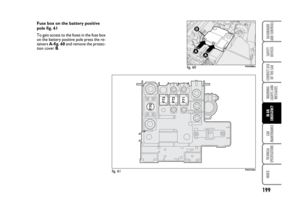
Fuse box on the battery positive
pole fig. 61
To gain access to the fuses in the fuse box
on the battery positive pole press the re-
tainers A-fig. 60and remove the protec-
tion cover B.
fig. 61F0C0152m
fig. 60F0C0499m