Page 2369 of 5267
TA N K - F U E L
DESCRIPTION
The fuel tank is similar to the tank used with gasoline powered models. The tank is equipped with a separate fuel
return line and a different fuel tank module for diesel powered models. Theelectric fuel transfer pump (lift pump) is
attached to the fuel pump module. Refer to Fuel Tank Module for additional information.
REMOVAL
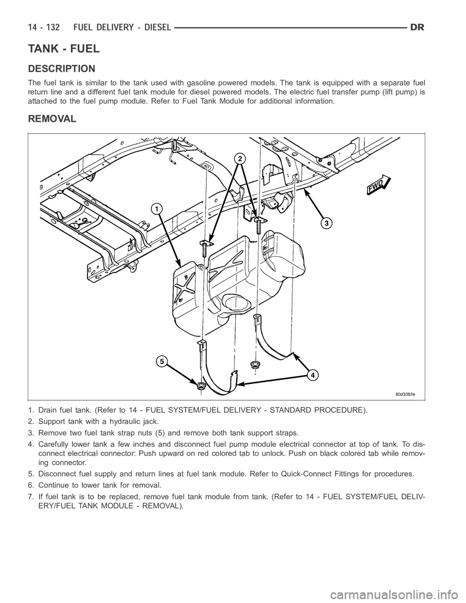
1. Drain fuel tank. (Refer to 14 - FUEL SYSTEM/FUEL DELIVERY - STANDARD PROCEDURE).
2. Support tank with a hydraulic jack.
3. Remove two fuel tank strap nuts (5) and remove both tank support straps.
4. Carefully lower tank a few inches and disconnect fuel pump module electrical connector at top of tank. To dis-
connect electrical connector: Push upward on red colored tab to unlock. Push on black colored tab while remov-
ing connector.
5. Disconnect fuel supply and return lines at fuel tank module. Refer to Quick-Connect Fittings for procedures.
6. Continue to lower tank for removal.
7. If fuel tank is to be replaced, remove fuel tank module from tank. (Refer to 14 - FUEL SYSTEM/FUEL DELIV-
ERY/FUEL TANK MODULE - REMOVAL).
Page 2370 of 5267
INSTALLATION
1. If fuel tank is to be replaced, install fuel tank mod-
ule into tank. (Refer to 14 - FUEL SYSTEM/FUEL
DELIVERY/FUEL TANK MODULE - REMOVAL).
2. Position fuel tank (1) to hydraulic jack.
3. Raise tank until positioned near body.
4. Connect fuel tank module electrical connector at
top of tank.
5. Connect fuel supply and return lines to tank mod-
ule.
6. Continue raising tank until positioned snug to body.
7. Install and position both tank support straps (4).
Install 2 fuel tank strap nuts and tighten to 41 Nꞏm
(30 ft. lbs.).Tighten rear strap nut first.
8. Remove hydraulic jack.
9. Connect rubber fill hose to fuel fill tube and tighten
clamp.
10. Install tire / wheel (if necessary).
11. Lower vehicle.
12. Fill fuel tank with fuel.
13. Start engine and check for fuel leaks near top of module.
Page 2371 of 5267
MODULE - FUEL TANK
DESCRIPTION
.
The fuel tank module is installed in the top of the fuel tank. The fuel tank module contains the following compo-
nents:
An electric fuel transfer (lift) pump
Fuel reservoir
A separate in-tank fuel filter
Fuel gauge sending unit (fuel level sensor)
Fuel supply line connection
A special lockring to retain module to fuel tank
Fuel return line connection
OPERATION
Refer to Fuel Gauge Sending Unit.
REMOVAL
1. Drain and remove fuel tank (Refer to 14 - FUEL
SYSTEM/FUEL DELIVERY/FUEL TANK -
REMOVAL).
2. Note rotational position of module before attempt-
ing removal. An indexing arrow is located on top of
module for this purpose.
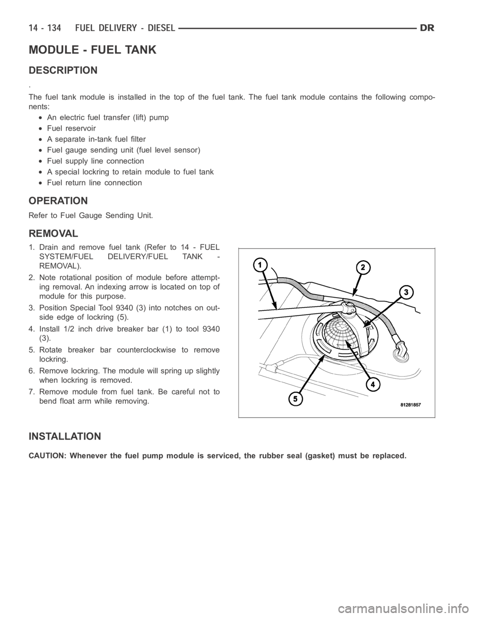
3. Position Special Tool 9340 (3) into notches on out-
side edge of lockring (5).
4. Install 1/2 inch drive breaker bar (1) to tool 9340
(3).
5. Rotate breaker bar counterclockwise to remove
lockring.
6. Remove lockring. The module will spring up slightly
when lockring is removed.
7. Remove module from fuel tank. Be careful not to
bend float arm while removing.
INSTALLATION
CAUTION: Whenever the fuel pump module is serviced, the rubber seal (gasket) must be replaced.
Page 2373 of 5267
PUMP - FUEL TRANSFER
DESCRIPTION
The fuel transfer pump (fuel lift pump) is part of the fuel pump module. The fuel pump module is located in the fuel
tank. The 12–volt electric pump is operated and controlled by the Engine Control Module (ECM). The ECM controls
a relay in the Intelligent Power Module(IPM) for transfer pump operation.
OPERATION
The purpose of the fuel transfer pump is to supply (transfer) a low-pressure fuel source:fromthe fuel tank,through
the fuel filter/water separator andtothe fuel injection pump. Here, the low-pressure is raised to a high-pressure by
the fuel injection pump for operation of the high-pressure fuel injectors. Check valves within the pump, control direc-
tion of fuel flow and prevent fuel bleed-back during engine shut down.
Maximum current flow to the pump is 5 amperes.
With the engine running, the pump has a 100 percent duty-cycle.
The transfer pump is self-priming: When the key is first turned on (withoutcranking engine), the pump will operate
for approximately 2 seconds and then shut off (Note: When ambient temperatures are cold enough to cause the
intake air heaters to operate, the fuel lift pump will operate during the entire intake air pre-heat cycle). The pump will
also operate for up to 25 seconds after the starter is engaged, and then disengaged and the engine is not running.
The pump shuts off immediately if the key is on and the engine stops running.
The fuel volume of the transfer pump will always provide more fuel than the fuel injection pump requires. Excess
fuel is returned from the injection pump through an overflow valve, and then back to the fuel tank.
REMOVAL
The fuel transfer pump (fuel lift pump) is a part of the fuel tank module. It is not serviced separately. Refer to Fuel
Tank Module Removal or Installation for procedures (Refer to 14 - FUEL SYSTEM/FUEL DELIVERY/FUEL TANK
MODULE - REMOVAL).
INSTALLATION
The fuel transfer pump (fuel lift pump) is a part of the fuel tank module. It is not serviced separately (Refer to 14 -
FUEL SYSTEM/FUEL DELIVERY/FUEL TANK MODULE - INSTALLATION).
Page 2375 of 5267
SENSOR-WATER IN FUEL
DESCRIPTION
The Water-In-Fuel (WIF) sensor (5) is located on the
side of the fuel filter/water separator canister.
OPERATION
The sensor sends an input to the Engine Control Module (ECM) when it senses water in the fuel filter/water sep-
arator. As the water level in the filter/separator increases, the resistance across the WIF sensor decreases. This
decreaseinresistanceissentasasignaltotheECMandcomparedtoahighwater standard value. Once the value
reaches 30 to 40 kilohms, the ECM will activate the water-in-fuel warning lamp through CCD bus circuits. This all
takes place when the ignition key is initially put in the ON position. The ECM continues to monitor the input while
the engine is running.
REMOVAL
The Water-In-Fuel (WIF) sensor is located at the side of fuel filter/waterseparator canister. (Refer to 14 - FUEL
SYSTEM/FUEL DELIVERY/FUEL TANK MODULE - INSTALLATION).
Page 2384 of 5267
ACTUATOR - FUEL CONTROL
DESCRIPTION
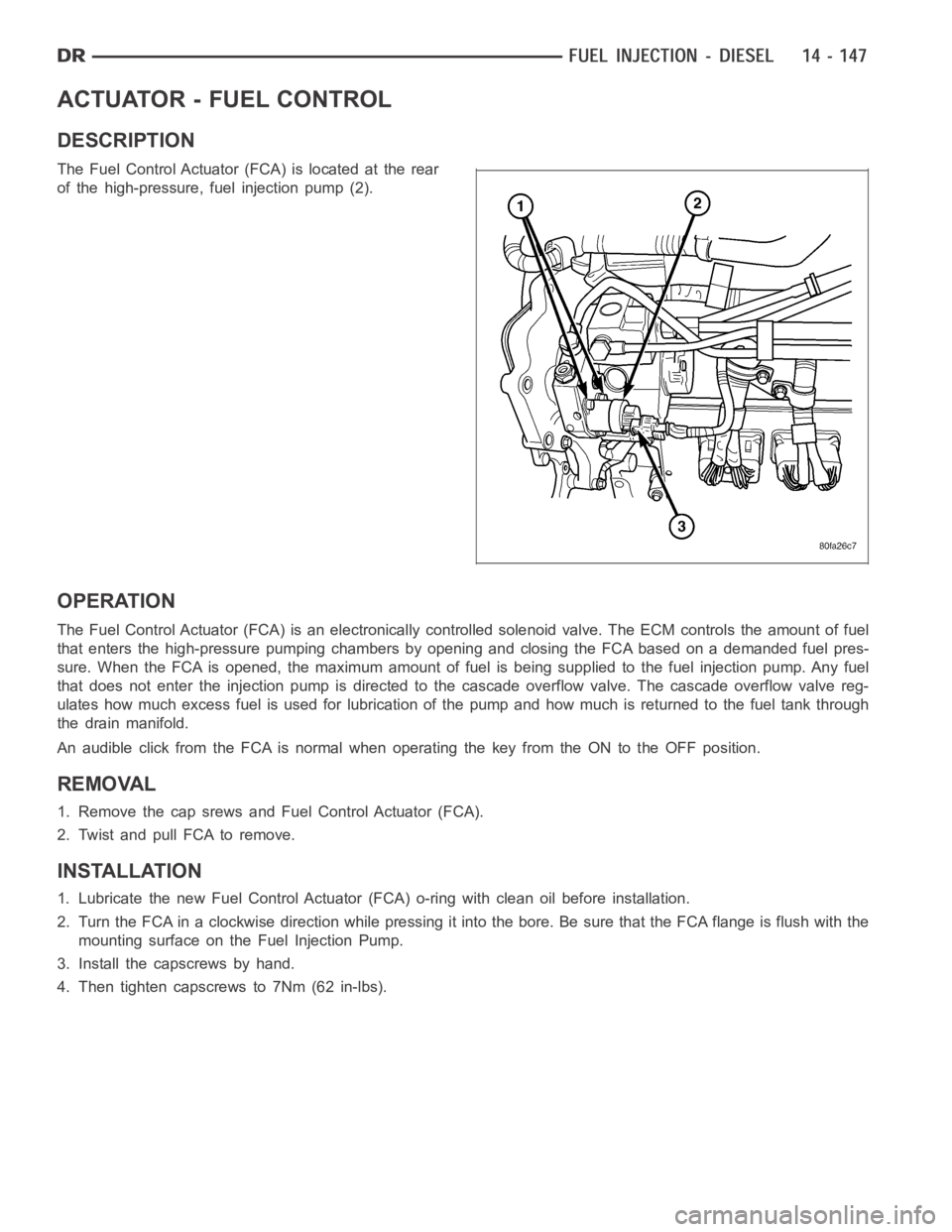
The Fuel Control Actuator (FCA) is located at the rear
of the high-pressure, fuel injection pump (2).
OPERATION
The Fuel Control Actuator (FCA) is an electronically controlled solenoidvalve. The ECM controls the amount of fuel
that enters the high-pressure pumping chambers by opening and closing theFCA based on a demanded fuel pres-
sure. When the FCA is opened, the maximum amount of fuel is being supplied tothe fuel injection pump. Any fuel
that does not enter the injection pump is directed to the cascade overflow valve. The cascade overflow valve reg-
ulates how much excess fuel is used for lubrication of the pump and how much is returned to the fuel tank through
the drain manifold.
An audible click from the FCA is normal when operating the key from the ON to the OFF position.
REMOVAL
1. Remove the cap srews and Fuel Control Actuator (FCA).
2. Twist and pull FCA to remove.
INSTALLATION
1. Lubricate the new Fuel Control Actuator (FCA) o-ring with clean oil before installation.
2. Turn the FCA in a clockwise direction while pressing it into the bore. Be sure that the FCA flange is flush with the
mounting surface on the Fuel Injection Pump.
3. Install the capscrews by hand.
4. Then tighten capscrews to 7Nm (62 in-lbs).
Page 5206 of 5267
CAP - FUEL FILLER
DESCRIPTION
The plastic fuel tank filler tube cap isthreaded onto the end of the fuel fill tube. Certain models are equipped with
a 1/4 turn cap.
OPERATION
The loss of any fuel or vapor out of fuel filler tube is prevented by the use ofa pressure-vacuum fuel fill cap. Relief
valves inside the cap will release fuel tank pressure at predetermined pressures. Fuel tank vacuum will also be
released at predetermined values. This cap must be replaced by a similar unit if replacement is necessary. This is
in order for the system to remain effective.
CAUTION: Remove fill cap before servicing any fuel system component to relieve tank pressure. If equipped
with a Leak Detection Pump (LDP), or NVLD system, the cap must be tightened securely. If cap is left loose,
a Diagnostic Trouble Code (DTC) may be set.
REMOVAL
REMOVAL/INSTALLATION
If replacement of the 1/4 turn fuel tank filler tube cap is necessary, it mustbereplacedwithanidenticalcaptobe
sure of correct system operation.
CAUTION: Remove the fuel tank filler tube cap to relieve fuel tank pressure. The cap must be removed prior
to disconnecting any fuel system component or before draining the fuel tank.
Page 5210 of 5267
REMOVAL
The Leak Detection Pump (LDP) (4) and LDP filter are attached to the front ofthe EVAP canister mounting bracket.
This is located near the front of the fuel tank. The LDP and LDP filter are replaced (serviced) as one unit.
1. Raise and support vehicle.
2. Certain models, equipped with a certain fuel tank size, may require the removal of the fuel tank skid plate and/or
the transfer case skid plate to gain access to the leak pump. Remove necessary skid plates.
3. Carefully remove hose at LDP filter.
4. Remove LDP filter mounting bolt and remove from vehicle.
5. Carefully remove vapor/vacuum lines at LDP.
6. Disconnect electrical connector at LDP.
7. Remove LDP mounting bolt and remove LDP from vehicle.