Page 1144 of 2893
���� ����
�(�#��������
���
�����
�����
���
�
�
� �����)����
14-22814-228 Automatic Transmission
2nd Clutch Transmission Fluid
Pressure Sw")
���
����
�(�#�'�������
���
�����
�����
���
���
� �����)���� ����
�(�#�'�������
���
�����
�����
���
�
�
� �����)����
14-22814-228 Automatic Transmission
2nd Clutch Transmission Fluid
Pressure Switch Replacement
3rd Clutch Transmission Fluid
Pressure Switch Replacement
A
B
A
20 N·m (2.0 kgf·m, 14 lbf·ft) B
B
20 N·m
(2.0 kgf·m, 14 lbf·ft)
A C
1. Remove the intake air duct (see page 11-348) and
the air cleaner assembly (see page 11-345).
2. Remove the harness cover (A) from its bracket (B).
3. Disconnect the 2nd clutch transmission fluid pressure switch connector, and remove the 2nd
clutch transmission fluid pressure switch (A).
4. Install a new 2nd clutch transmission fluid pressure switch with a new sealing washer (B), and tighten
the metal part of the switch, not the plastic part.
5. Check the connector for rust, dirt, or oil, clean or repair if necessary, then connect the connector
securely.
6. Install the harness cover on its bracket.
7. Install the air cleaner assembly (see page 11-345) and the intake air duct (see page 11-348). 1. Do the battery removal procedure (see page 22-69).
2. Remove the intake air duct (see page 11-348) and
the air cleaner assembly (see page 11-345).
3. Remove the battery tray, the battery base, and the resonator.
4. Disconnect the 3rd clutch transmission fluid pressure switch connector (A), then remove the 3rd
clutch transmission fluid pressure switch (B) with
the sealing washer (C).
5. Install a new 3rd clutch transmission fluid pressure switch with a new sealing washer, and tighten the
metal part of the switch, not the plastic part.
6. Check the connector for rust, dirt, or oil, clean or repair if necessary, then connect the connector
securely.
7. Install the battery tray, the battery base, and the resonator.
8. Install the air cleaner assembly (see page 11-345) and the intake air duct (see page 11-348).
9. Do the battery installation procedure (see page 22-69).
Replace.
Replace.
08/08/21 14:46:50 61SNR030_140_0230
ProCarManuals.com
DYNOMITE -2009-
Page 1146 of 2893

C
D
B
A
6x1.0mm
12 N·m
(1.2 kgf·m, 8.7 lbf·ft) E
G F
10. Measure the ATF temperature sen")
�����
�µStandard: 50 25 k
14-230Automatic Transmission
ATF Temperature Sensor Test/Replacement (cont’d)
C
D
B
A
6x1.0mm
12 N·m
(1.2 kgf·m, 8.7 lbf·ft) E
G F
10. Measure the ATF temperature sensor resistance between shift solenoid wire harness connector
terminals No. 6 and No. 7.
If the resistance is within the standard, install the shift solenoid wire harness and a new O-ring in
the transmission, then go to step 13.
If the resistance is out of standard, go to step 11.
11. Disconnect the connectors from the shift solenoid valves, and replace the ATF temperature sensor/
shift solenoid harness assembly (F) and the O-ring
(G) with new ones.
NOTE: The ATF temperature sensor is not available
separately from the shift solenoid wire harness.
12. Connect the shift solenoid valve connectors: BLU wire to shift solenoid valve A.
ORN wire to shift solenoid valve B.
GRN wire to shift solenoid valve C.
YEL, WHT, and WHT wire connector to shiftsolenoid valve D.
RED wire to shift solenoid valve E.
13. Install a new gasket, the dowel pins, and the shift solenoid valve cover.
14. Check the connector for rust, dirt, or oil, clean or repair if necessary, then connect the connector
securely. 15. Refill the transmission with ATF (see step 5 on page
14-232).
16. Install the battery tray, the battery base, and the resonator.
17. Install the air cleaner assembly (see page 11-345) and the intake air duct (see page 11-348).
18. Do the battery installation procedure (see page 22-69).
19. Install the splash shield.
Replace.
08/08/21 14:46:51 61SNR030_140_0232
ProCarManuals.com
DYNOMITE -2009-
Page 1148 of 2893
����
Automatic Transmission Fluid Capacity:
2.9 L (3.1 US qt) at change
6.5 L (6.9 US qt) at overhaul
14-232 Automatic Transmission
ATF R")
����
���� ����
�(�#�'�������
���
�����������
�������
� �����)����
Automatic Transmission Fluid Capacity:
2.9 L (3.1 US qt) at change
6.5 L (6.9 US qt) at overhaul
14-232 Automatic Transmission
ATF Replacement
A
18 x 1.5 mm
49 N·m
(5.0 kgf·m,
36 lbf·ft)
B
ATF
A
NOTE: Keep all foreign particles out of the transmission. 1. Park the vehicle on the level ground.
2. Warm up the engine to normal operating temperature (the radiator fan comes on), and turn
the engine off.
3. Remove the drain plug (A), and drain the automatic transmission fluid (ATF).
4. Reinstall the drain plug with a new sealing washer (B).
5. Refill the transmission with ATF into the dipstick hole to bring the fluid level between the upper
mark and the lower mark of the dipstick. Always
use Acura ATF-Z1 automatic transmission fluid
(ATF). Using a non-Acura ATF can affect shift
quality.
6. Check that the ATF level is between the upper mark
and the lower mark of the dipstick.
7. Insert the dipstick back into the transmission with the letters ‘‘ATF’’ pointing toward the front of the
vehicle. 8. If the maintenance minder required to replace the
ATF, reset the maintenance minder (see page 3-4),
and this procedure is complete. If the maintenance
minder did not require you to replace the ATF, go
to step 9.
9. Connect the HDS to the DLC (A) located under the driver’s side of the dashboard.
10. Turn the ignition switch to ON (II). Make sure the HDS communicates with the PCM. If it does not, go
to the DLC circuit troubleshooting (see page
11-204).
11. Select BODY ELECTRICAL with the HDS.
12. Select ADJUSTMENT in the GAUGES MENU with the HDS.
13. Select RESET in the MAINTENANCE MINDER MENU with the HDS.
14. Select RESETTING THE ATF with the HDS.
NOTE: If you changed the engine oil at the same
time with the ATF, select RESETTING THE ENGINE
OIL LIFE AND ATF with the HDS instead.
Replace.
08/08/21 14:46:53 61SNR030_140_0234
ProCarManuals.com
DYNOMITE -2009-
Page 1156 of 2893
����
��������
����
14-240Automatic Transmission
Transmission Removal (cont’d)
A
B
A B
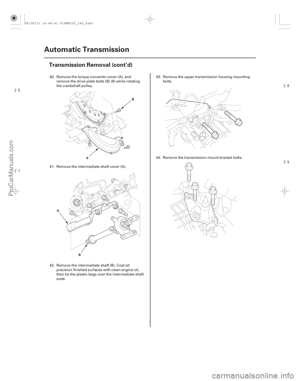
40. Remove the torque converter cover (A), andremove the drive plate bolts (B) (8) while rotating
the crankshaft pulley.
41. Remove the intermediate shaft cover (A).
42. Remove the intermediate shaft (B). Coat all precision finished surfaces with clean engine oil,
then tie the plastic bags over the intermediate shaft
ends. 43. Remove the upper transmission housing mounting
bolts.
44. Remove the transmission mount bracket bolts.
08/08/21 14:48:41 61SNR030_140_0242
ProCarManuals.com
DYNOMITE -2009-
Page 1182 of 2893
: 6.1 6.2 mm (0.240 0.244 in.)
End Gap (C): 1.8 2.0 mm (0.07 0.08 in.)
14-266A/T Gear Position")
����
����� ����
�µ
�µ�µ
�µ�µ
Transmission Range Switch Connector Selector Control Shaft:
Width (B): 6.1 6.2 mm (0.240 0.244 in.)
End Gap (C): 1.8 2.0 mm (0.07 0.08 in.)
14-266A/T Gear Position Indicator
Transmission Range Switch Test (cont’d)
Connector Terminal/Signal
25
134
687910
P
R
N
D
S
Posi-
tion A
C
B
ATP
NP ATP
FWD
GND
ATP
RVS ATP
N ATP
S ATP
PATP
R ATP
D
7. Disconnect the transmission range switch
connector.
8. Check for continuity between the terminals at the switch connector. There should be continuity
between the terminals in the following table for
each switch position.
9. If the transmission range switch test is OK, replace the faulty transmission range switch harness, then
go to step 12. If there is no continuity between any
terminals, go to step 10. 10. Remove the transmission range switch, and check
the end of the selector control shaft (A).
11. If the measurement at the end of the selector control shaft is within the standard, replace the
transmission range switch. If the measurement is
out of the standard, repair the selector control shaft
end, and recheck the transmission range switch
continuity.
12. Check the connector for rust, dirt, or oil, clean or repair if necessary, then connect the connector
securely.
13. Install the removed parts in the reverse order of removal.
08/08/21 14:49:01 61SNR030_140_0268
ProCarManuals.com
DYNOMITE -2009-
Page 1184 of 2893

A
C
B
6x1.0mm
12 N·m (1.2 kgf·m, 8.7 lbf·ft) 6x1.0mm
12 N·m (1.2 kgf·m, 8.7 lbf·ft)A
7. Install t")
����
��������
14-268A/T Gear Position Indicator
Transmission Range Switch Replacement (cont’d)
A
C
B
6x1.0mm
12 N·m (1.2 kgf·m, 8.7 lbf·ft) 6x1.0mm
12 N·m (1.2 kgf·m, 8.7 lbf·ft)A
7. Install the transmission range switch (A) gently on
the selector control shaft (B) while holding it in the
N position with the 2.0 mm (0.08 in.) blade (C).
8. Tighten the bolts on the transmission range switch while you continue to holding the N position. Do
not move the transmission range switch when
tightening the bolts. Remove the feeler gauge. 9. Check the connectors for rust, dirt, or oil, clean or
repair if necessary, then connect the connector
securely.
10. Turn the ignition switch to ON (II). Move the shift lever through all positions, and check the
transmission range switch synchronization with the
A/T gear position indicator.
11. Check that the engine will start with the shift lever in P and N, and will not start in any other shift lever
position.
12. Check that the back-up lights come on when the shift lever is in R.
13. Allow the front wheels to rotate freely, then start the engine, and check the shift lever operation.
14. Install the transmission range switch cover (A).
08/08/21 14:49:03 61SNR030_140_0270
ProCarManuals.com
DYNOMITE -2009-
Page 1230 of 2893
����
Special Tools Required
14-308
Torque Converter Housing
Mainshaft Bearing and Oil Seal Replacement
07736-A01000B or
07736-A01000A
A")
�µ
���
���� ����
�(�#�'�������
���
�����
�
�����������
� �����)����
Special Tools Required
14-308
Torque Converter Housing
Mainshaft Bearing and Oil Seal Replacement
07736-A01000B or
07736-A01000A
A
07749-001000007746-0010500 07749-0010000
07746-0010600
Adjustable bearing puller, 25 40 mm07736-A01000B or 07736-A01000A
Driver 07749-0010000
Attachment, 62 x 68 mm 07746-0010500
Attachment, 72 x 75 mm 07746-0010600
1. Remove the mainshaft bearing and the oil seal using the adjustable bearing puller and a
commercially available 3/8 ’’-16 slide hammer (A).
2. Install a new mainshaft bearing until it bottoms in the housing using the driver and the 62 x 68 mm
attachment. 3. Install a new oil seal flush using the housing using
thedriverandthe72x75mmattachment.
NOTE: Do not drive the seal into the torque
converter housing until it bottoms out; it will block
the fluid return passage and cause transmission
damage.
08/08/21 14:51:16 61SNR030_140_0310
ProCarManuals.com
DYNOMITE -2009-
Page 1283 of 2893
���
�������
����
�(�#�'�������
���
�����
�
���
�������
� �����)����
Special Tools Required
14-358
A/T Differential
Oil Seal Replacement
07749-0010000
07947-SD90101
A
07749-0010000
07JAD-PH80101
A
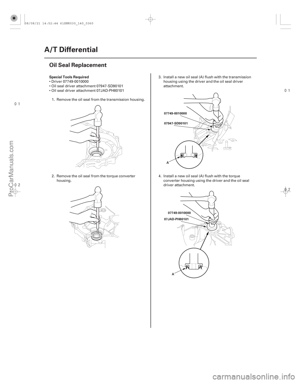
Driver 07749-0010000
Oil seal driver attachment 07947-SD90101
Oil seal driver attachment 07JAD-PH801011. Remove the oil seal from the transmission housing.
2. Remove the oil seal from the torque converter housing. 3. Install a new oil seal (A) flush with the transmission
housing using the driver and the oil seal driver
attachment.
4. Install a new oil seal (A) flush with the torque converter housing using the driver and the oil seal
driver attachment.
08/08/21 14:52:44 61SNR030_140_0360
ProCarManuals.com
DYNOMITE -2009-