Page 1520 of 2893
����
19-24 Conventional Brake Components
Master Cylinder Replacement
B
6x1.0mm
9.8 N·m (1.0 kgf·m, 7.2 lbf·ft)
A B
D
E G
MASTER
CYLINDER SIDE")
���
���
�(�#�'�����������
�����������
�������
� �����)����
19-24 Conventional Brake Components
Master Cylinder Replacement
B
6x1.0mm
9.8 N·m (1.0 kgf·m, 7.2 lbf·ft)
A B
D
E G
MASTER
CYLINDER SIDE
A
ABS: 15 N·m
(1.5 kgf·m, 11 lbf·ft)
VSA: 22 N·m
(2.2 kgf·m, 16 lbf·ft) C
15 N·m
(1.5 kgf·m,
11 lbf·ft)
D
F
Do not spill brake fluid on the vehicle; it may damage the paint; if brake fluid gets on the paint,
wash it off immediately with water.
Be careful not to damage or deform the brake lines during removal and installation.
Plug the ends of the hoses and the joints to prevent spilling brake fluid.
1. Remove the air cleaner (see page 11-345).
2. Remove the reservoir cap and brake fluid from the master cylinder reservoir with a syringe.
3. Disconnect the brake fluid l evel switch connector
(A).
4. Remove the reservoir tank mounting bolt (B). 5. Disconnect the brake lines (A) from the master
cylinder (B). To prevent spills, cover the hose joints
with clean rags or shop towels.
6. Remove the master cylinder mounting nuts (C) and washers (D).
7. Remove the master cylinder from the brake booster (E). Be careful not to bend or damage the brake
lines when removing the master cylinder.
8. Remove the rod seal (F) from the master cylinder. NOTE: During installation, set a new rod seal onto
the master cylinder with its grooved side (G)
toward the master cylinder.
9. Install the master cylinder in the reverse order of removal, and note these items:
Coat the inner bore lip and outer circumference of the new rod seal with the Shin-Etsu silicone
grease (P/N 08798-9013).
Make sure not to get any silicone grease on the terminal part of the connectors and switches,
especially if you have silicone grease on your
hands or gloves.
Check the brake pedal height and free play after installing the master cylinder, and adjust it if
necessary (see page 19-6).
10. Bleed the brake system (see page 19-9).
11. Spin the wheels to check for brake drag.
Replace.
08/08/21 15:00:59 61SNR030_190_0024
ProCarManuals.com
DYNOMITE -2009-
Page 1538 of 2893
����
���� �����
�(�#�'�����������
�����������
��������� �����)����
19-45
Brake Pedal Cover Replacement
A B
C
A
B
C A
B
B
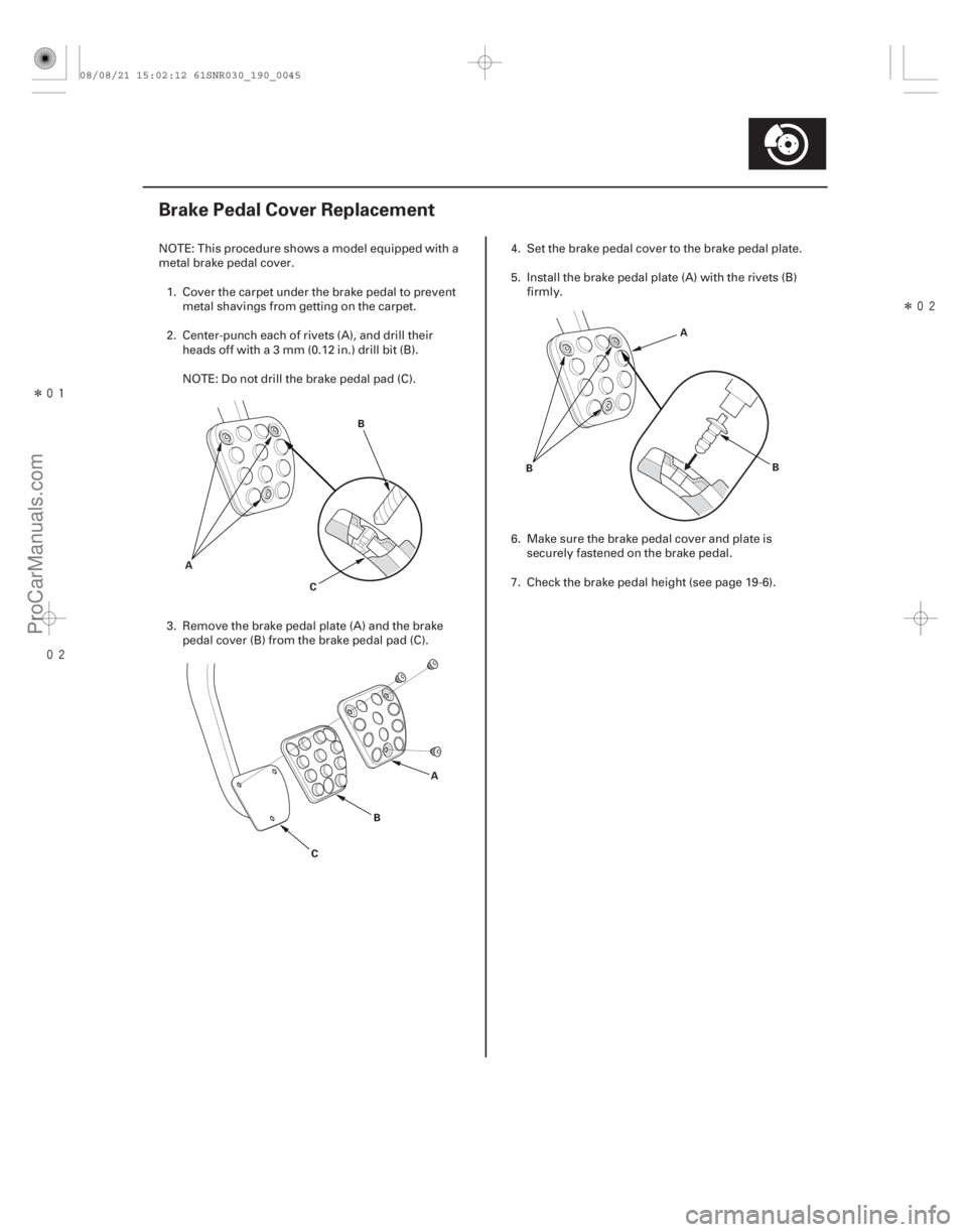
NOTE: This procedure shows a model equipped with a
metal brake pedal cover.
1. Cover the carpet under the brake pedal to pr event
metal shavings from getting on the carpet.
2. Center-punch each of rivets (A), and drill their heads off with a 3 mm (0.12 in.) drill bit (B).
NOTE: Do not drill the brake pedal pad (C).
3. Remove the brake pedal plate (A) and the brake pedal cover (B) from the brake pedal pad (C). 4. Set the brake pedal cover to the brake pedal plate.
5. Install the brake pedal plate (A) with the rivets (B)
firmly.
6. Make sure the brake pedal cover and plate is securely fastened on the brake pedal.
7. Check the brake pedal height (see page 19-6).
08/08/21 15:02:12 61SNR030_190_0045
ProCarManuals.com
DYNOMITE -2009-
Page 1643 of 2893
����
�µ
�µ
�µ
�µ
�µ
�µ �µ
�µ
DTC 68-22:
YES
NO
YES
NO
YES
NO YES
NO
19-151
BRAKE PEDAL POSITION SWITCH 4P CONNECTOR
BKSW (LT GRN)
Brake Pedal")
���
�(�#�'��������� �����
�������'���������������)����
�µ
�µ
�µ
�µ
�µ
�µ �µ
�µ
DTC 68-22:
YES
NO
YES
NO
YES
NO YES
NO
19-151
BRAKE PEDAL POSITION SWITCH 4P CONNECTOR
BKSW (LT GRN)
Brake Pedal Position Switch Stuck
ON
1. Turn the ignition switch to ON (II).
2. Check the BRAKE PRESS in the VSA DATA LIST
with the HDS. Do not press the brake pedal.
Check the brake pedal height and the brake
pedal position switch adjustment (see page 19-6). If
the brake pedal height is OK, replace the VSA
modulator-control unit and the brake pedal position
switch adjustment (see page 19-171).
Go to step 3.
3. Check the BRAKE SWITCH in the VSA DATA LIST with the HDS while moving the brake pedal.
Intermittent failure, the system is OK at this
time.
Go to step 4.
4. Check the BRAKE SWITCH in the VSA DATA LIST with the HDS, and disconnect the brake pedal
position switch 4P connector.
Inspect the brake pedal switch and
adjustment (see page 19-6). If the switch and
adjustment are OK, replace the brake pedal
position switch (see page 19-6).
Go to step 5. 5. Turn the ignition switch to LOCK (0).
6. Short the SCS line with the HDS.
7. Disconnect ECM/PCM connector A (44P).
8. Turn the ignition switch to ON (II).
9. Measure the voltage between brake pedal position
switch 4P connector terminal No. 2 and body
ground.
Repair short to power in the wire between
the ECM/PCM and the brake pedal position
switch.
Update the ECM/PCM if it does not have the
latest software (see page 11-227), or substitute a
known-good ECM/PCM (see page 11-7), then go to
step 1, and recheck. If the ECM/PCM was updated
and DTCs are not indicated, troubleshooting is
complete. If the ECM/PCM was substituted and
DTCs are not indicated, replace the original ECM/
PCM (see page 11-228).
Wire side of female terminals
Is it 10 MPa or more?
Does i t i nd i cat e ON w hen t he ped al i s pr essed ,and OF F w hen t he ped al i s r el eased ?
Does t he i nd i cat or change f r om ON t o OF F ? Is t her e 0.1 V or mor e?
08/08/21 15:06:41 61SNR030_190_0151
ProCarManuals.com
DYNOMITE -2009-
Page 1805 of 2893
�
��
S
pecial Tools Required
20-127
Front Seat Cushion Cover Replacement
Fastener Locations
AB
C
:Screw,2
BFas
tener Locations
:Screw,1
C:Clip,")
���
���
�(�#�'���������������
����������������� �����)�
��
S
pecial Tools Required
20-127
Front Seat Cushion Cover Replacement
Fastener Locations
AB
C
:Screw,2
BFas
tener Locations
:Screw,1
C:Clip,1
AB
B
A
Passenger’s seat
Driver’s seat C
KTC trim tool set SOJATP2014
SRS components are located in this area. Review the
S
RS component locations (see page 24-11) and the
precautions and procedures (see page 24-13) before
doing repairs or service.
Check the operation of the driver’s seat position sensor after any of these actions (see page 24-29):
– Driver’s seat position sensor replacement
– Cover plate (front side of driver’s seat slide rail) replacement
Calibrate the ODS unit after any of these actions (see page 24-27):
– Front passenger’s seat replacement (including any seat components)
– Replacement of the front seat weight sensors
– After a vehicle collision
NOTE: Use the appropriate tool from the KTC trim tool set to avoid damage when removing components.
Take care not to tear or damage the seat covers.
Put on gloves to protect your hands.
1. Remove the front seat (see page 20-118).
2. Remove the front seat belt buckle (see page 24-6).
3. Pull back the cap (A) to release the hooks (B), and remove the screws, then remove the height
adjuster handle (C). 4.
Remove the recline cover (A).
–1 Remove the recline knob (B) and the screw.
–2 Gently pull out the cover, then detach the clip, and release the hooks (C).
(cont’d)
08/08/21 15:03:59 61SNR030_200_0129
ProCarManuals.com
DYNOMITE -2009-
Page 2121 of 2893
���
����
����
�(�#�'���������������
�����
���
�
���
�"�����)����
22-173
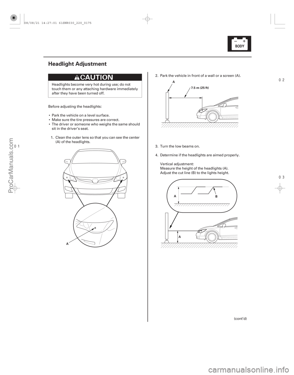
Headlight Adjustment
A A
7.5 m (25 ft)
A A B
Headlights become very hot during use; do not
touch them or any attaching hardware immediately
after they have been turned off.
Before adjusting the headlights: Park the vehicle on a level surface.
Make sure the tire pressures are correct.
The driver or someone who weighs the same should sit in the driver’s seat.
1. Clean the outer lens so that you can see the center (A) of the headlights. 2. Park the vehicle in front of a wall or a screen (A).
3. Turn the low beams on.
4. Determine if the headlights are aimed properly.
Vertical adjustment:
Measure the height of the headlights (A).
Adjust the cut line (B) to the lights height.
(cont’d)
08/08/21 14:27:01 61SNR030_220_0175
ProCarManuals.com
DYNOMITE -2009-
Page 2130 of 2893
���
����
�(�#����������������
�
�����
���������������)����
TYPE S model
22-18122-181
Brake Pedal Position Switch Test
A B
A
B
1. Remove the two s")
���
�(�#�'���������������
�
�������
�����
� �����)���
����
�(�#�'���������������
�
�����
���������������)����
TYPE S model
22-18122-181
Brake Pedal Position Switch Test
A B
A
B
1. Remove the two screws from the high mount brakelight (A).
2. Disconnect the terminals (B) and remove the high mount brake light.
3. Install the high mount brake light in the r everse
order of removal. 1. Disconnect the 4P connector (A) from the brake
pedal position switch (B).
2. Check for continuity between terminals No. 1 and No. 2.
There should be continuity when the brake pedal is pressed.
There should be no continuity when the brake pedal is released.
3. Check for continuity between terminals No. 3 and No. 4 (with cruise control).
There should be no continuity when the brake pedal is pressed.
There should be continuity when the brake pedal is released.
4. If necessary, adjust or replace the switch, or adjust the pedal height (see page 19-6).
08/08/21 14:27:41 61SNR030_220_0183
ProCarManuals.com
DYNOMITE -2009-
Page 2131 of 2893
���
����
�(�#����������������
�
�����
���������������)����
TYPE S model
22-18122-181
Brake Pedal Position Switch Test
A B
A
B
1. Remove the two s")
���
�(�#�'���������������
�
�������
�����
� �����)���
����
�(�#�'���������������
�
�����
���������������)����
TYPE S model
22-18122-181
Brake Pedal Position Switch Test
A B
A
B
1. Remove the two screws from the high mount brakelight (A).
2. Disconnect the terminals (B) and remove the high mount brake light.
3. Install the high mount brake light in the r everse
order of removal. 1. Disconnect the 4P connector (A) from the brake
pedal position switch (B).
2. Check for continuity between terminals No. 1 and No. 2.
There should be continuity when the brake pedal is pressed.
There should be no continuity when the brake pedal is released.
3. Check for continuity between terminals No. 3 and No. 4 (with cruise control).
There should be no continuity when the brake pedal is pressed.
There should be continuity when the brake pedal is released.
4. If necessary, adjust or replace the switch, or adjust the pedal height (see page 19-6).
08/08/21 14:27:41 61SNR030_220_0183
ProCarManuals.com
DYNOMITE -2009-