Page 244 of 2893

����
�
���µ�µ
�µ
�µ
Oil Seal Installed Height: 0.2 1.2 mm
(0.001 0.047 in.)
7-28Engine Block
Crankshaft Installation (cont’d)
0.2 1.2 mm
(0.001 0.047 in.)
BA
6x1.0mm
12 N·m
(1.2 kgf·m, 8.7 lbf·ft)
25. Measure the distance between the engine block (A) and the crankshaft oil seal (B).
26. Install the baffle plates. 27. Install the oil pump (see page 8-21).
28. Install the oil pan (see page 7-29).
29. Install the cylinder head (see page 6-62).
30. M/T model: Install the flywheel (see page 12-21),
the clutch disc (see page 12-23), and the pressure
plate (see page 12-23).
31. A/T model: Install the drive plate (see page 14-242).
32. Install the transmission: Manual transmission (see page 13-14)
Automatic transmission (see page 14-242)
33. Install the engine assembly (see page 5-13). NOTE: Whenever any crankshaft or connecting rod
bearing is replaced, it is necessary after
reassembly to run the engine at idle speed until it
reaches normal operating temperature, then
continue to running it for about 15 minutes.
08/08/21 14:33:10 61SNR030_070_0028
ProCarManuals.com
DYNOMITE -2009-
Page 248 of 2893

���
����
�(�#�'�����������
�����
�����
�����
��� �����)����
�µ �µ
�µ
�µ
Special Tools Required
Oil Seal Installed Height: 0.2 1.2 mm(0.008 0.047 in.)
7-32Engine Block
Transmission End Crankshaft Oil Seal Installation - In Car
07749-0010000
07ZAD-PNAA100 0.2 1.2 mm
(0.008 0.047 in.)
B
A
Driver 07749-0010000
Oil seal driver attachment 96 07ZAD-PNAA100 1. Remove the transmission: Manual transmission (see page 13-7)
Automatic transmission (see page 14-233)
2. M/T model: Remove the pressure plate (see page 12-19), the clutch disc (see page 12-20), and the
flywheel (see page 12-21).
3. A/T model: Remove the drive plate (see page 14-242).
4. Clean, and dry the crankshaft oil seal housing.
5. Apply a light coat of new engine oil around the crankshaft oil seal.
6. Apply a light coat of new engine oil to the crankshaft and to the lip of the crankshaft oil seal.
7. Use the driver and the oil seal driver attachment 96 to drive a new oil seal squarely into the engine
block to the specified installed height. 8. Measure the distance between the engine block (A)
and the crankshaft oil seal (B).
9. M/T model: Install the flywheel (see page 12-21), the clutch disc (see page 12-23), and the pressure
plate (see page 12-23).
10. A/T model: Install the drive plate (see page 14-242).
11. Install the transmission: Manual transmission (see page 13-14)
Automatic transmission (see page 14-242)
08/08/21 14:33:12 61SNR030_070_0032
ProCarManuals.com
DYNOMITE -2009-
Page 279 of 2893
����
��������
���
Installation - K20Z2 engine
9-4Intake Manifold and Exhaust System
Intake Manifold Removal and Installation (cont’d)
A
B B
A
8x1.25mm
22 N·m
(2.2 kgf·m, 16 lbf·ft) B
A 8x1.25mm
22 N·m
(2.2 kgf·m, 16 lbf·ft)
7. Raise the vehicle on the lift to full height.
8. Remove the splash shield (see step 25 on page 5-5).
9. Remove the connector (A) from the intake manifoldbracket (B), then remove the intake manifold
bracket.
10. Lower the vehicle on the lift.
11. Remove the intake manifold. 1. Install the intake manifold (A) with a new gasket (B),
and tighten the bolts and the nuts in a crisscross
pattern in three steps, beginning with the inner bolt.
2. Raise the vehicle on the lift.
3. Install the intake manifold bracket (A), then install the connector (B) to the intake manifold bracket.
4. Install the splash shield (see step 40 on page 5-20).
5. Lower the vehicle on the lift.
08/08/21 14:37:31 61SNR030_090_0004
ProCarManuals.com
DYNOMITE -2009-
Page 294 of 2893

���
�(�#�'�����������
�������������������
�������)���
���
�(�#�'�����������
�������������������
�������)���� �µ�µ
Standard Thermostat
Lift Height: Above 8.0 mm (0.31 in.)
Starts Opening: 76 80 °C (169 176 °F)
Fully Open: 90 °C (194 °F)
10-510-5
Fan Motor Test
Thermostat Test
B
A
1. Disconnect the 2P connectors from the radiator fan motor and the A/C condenser fan motor.
2. Test the motor by connecting battery power to terminal No. 2 and ground to terminal No. 1.
3. If the motor fails to run or does not run smoothly, replace it (see page 10-19). Replace the thermostat if it is stuck in the open position
at room temperature.
To test a closed thermostat:
1. Suspend the thermostat (A) in a container of water. Do not let the thermostat and the thermometer (B)
touch the bottom of the hot container.
2. Heat the water, and check the temperature with a thermometer. Check the temperature when the
thermostat first opens, then check the temperature
again when the thermostat is fully open.
3. Measure the lift height of the thermostat when it is fully open. If it thermostat is not within the
specification, replace it.
Terminal side of
male terminals
08/08/21 14:39:57 61SNR030_100_0005
ProCarManuals.com
DYNOMITE -2009-
Page 750 of 2893

��������
�(�#�'���������������
�
�����
�������
�"�����)���� �µ�µ
F Clutch Pedal Height:
Except Type S model: 159.3 mm (6.27 in.)
Type S model: 161.3 mm (6.35 in.)
G Clutch Pedal Stroke: 130 140 mm (5.12 5.51 in.)
12-8Clutch
Clutch Pedal, Clutch Pedal Position Switch, and Clutch Interlock Switch
Adjustment
B
A F
G
A
D E
B
C
NOTE: For a cruise control problem, check the clutch pedal position switch (see page 4-50).
For an engine cranking problem, check the clutch interlock switch (see page 4-8).
The clutch is self-adjusting to compensate for wear.
If there is no clearance between the master cylinder piston and the pushrod, the release bearing will be
held against the diaphragm spring, which can result
in clutch slippage or other clutch problems.
1. Lift up the carpet (A). At the insulator cutout, measure pedal height from the right side of the
pedal pad (B). 2. Loosen the clutch pedal position switch locknut (A),
and back off the clutch pedal position switch (B)
until it no longer touches the clutch pedal (C).
3. Loosen the clutch pushrod locknut (D), and turn the pushrod (E) in or out to get the specified height (F)
and stroke (G) at the clutch pedal. If adjusting the
pushrod causes the clutch pedal to contact the
clutch pedal position switch, back off the switch
further.
08/08/21 14:42:30 61SNR030_120_0010
ProCarManuals.com
DYNOMITE -2009-
Page 751 of 2893

�µ�µ
�����
�����
�µ
�µ
12-9
A
18 N·m
(1.8 kgf·m,
13 lbf·ft) C
9.8 N·m
(1.0 kgf·m,
7.2 lbf·ft)
B A
9.8 N·m
(1.0 kgf·m,
7.2 lbf·ft)
B
912mm
(0.35 0.47 in.)
4. Tighten the clutch pushrod locknut (A).
5. With the clutch pedal released, turn in the clutch pedal position switch (B) until it contacts the clutch
pedal.
6. Turn in the clutch pedal position switch an additional 3/4 to 1 turn. Make sure the clutch pedal
height did not change.
7. While holding the clutch pedal position switch, tighten the locknut (C). 8. Loosen the clutch interlock switch locknut (A).
9. Fully press the clutch pedal to the floor, then
release the clutch pedal 9 12 mm (0.35 0.47 in.)
and hold it there.
10. Adjust the position of the clutch interlock switch (B), so the engine starts with the clutch pedal in this
position.
11. While holding the clutch interlock switch, tighten the locknut.
12. Check the clutch operation.
13. Connect the clutch pedal position switch connector and the clutch interlock switch connector, then
check the cruise control and the engine starting.
08/08/21 14:42:30 61SNR030_120_0011
ProCarManuals.com
DYNOMITE -2009-
Page 752 of 2893

���
����
����
�(�#�'���������������
�
��������������� �����)����
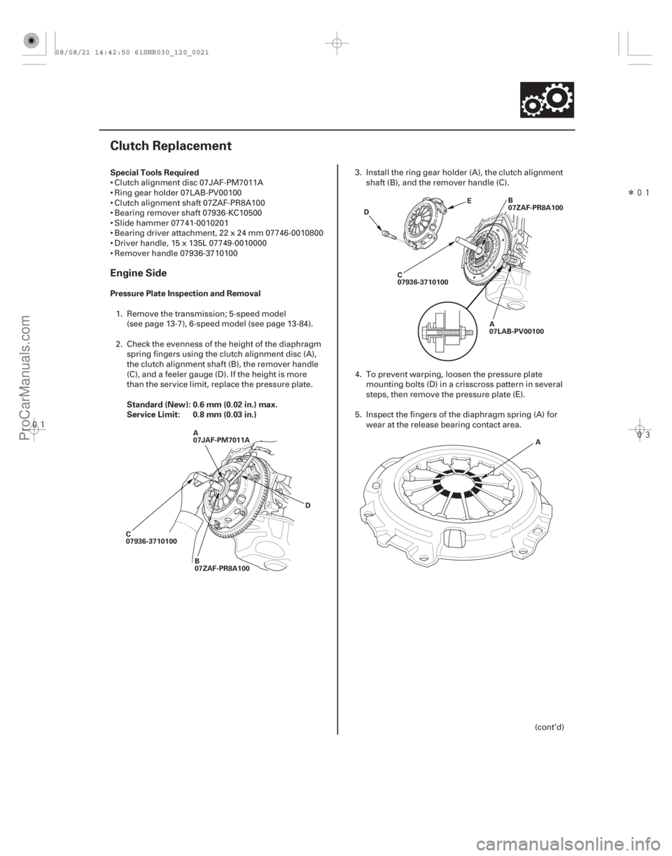
Special Tools Required
Pressure Plate Inspection and Removal
Standard (New): 0.6 mm (0.02 in.) max.
Service Limit: 0.8 mm (0.03 in.)
Engine Side
12-19
Clutch Replacement
A
07JAF-PM7011A
C
07936-3710100 B
07ZAF-PR8A100 DC
07936-3710100
A
07LAB-PV00100B
07ZAF-PR8A100
D E
A
Clutch alignment disc 07JAF-PM7011A
Ring gear holder 07LAB-PV00100
Clutch alignment shaft 07ZAF-PR8A100
Bearing remover shaft 07936-KC10500
Slide hammer 07741-0010201
Bearing driver attachment, 22 x 24 mm 07746-0010800
Driver handle, 15 x 135L 07749-0010000
Remover handle 07936-37101001. Remove the transmission; 5-speed model (see page 13-7), 6-speed model (see page 13-84).
2. Check the evenness of the height of the diaphragm spring fingers using the clutch alignment disc (A),
the clutch alignment shaft (B), the remover handle
(C), and a feeler gauge (D). If the height is more
than the service limit, replace the pressure plate. 3. Install the ring gear holder (A), the clutch alignment
shaft (B), and the remover handle (C).
4. To prevent warping, loosen the pressure plate mounting bolts (D) in a cri sscross pattern in several
steps, then remove the pressure plate (E).
5. Inspect the fingers of the diaphragm spring (A) for wear at the release bearing contact area.
(cont’d)
08/08/21 14:42:50 61SNR030_120_0021
ProCarManuals.com
DYNOMITE -2009-
Page 756 of 2893

����
�
�������
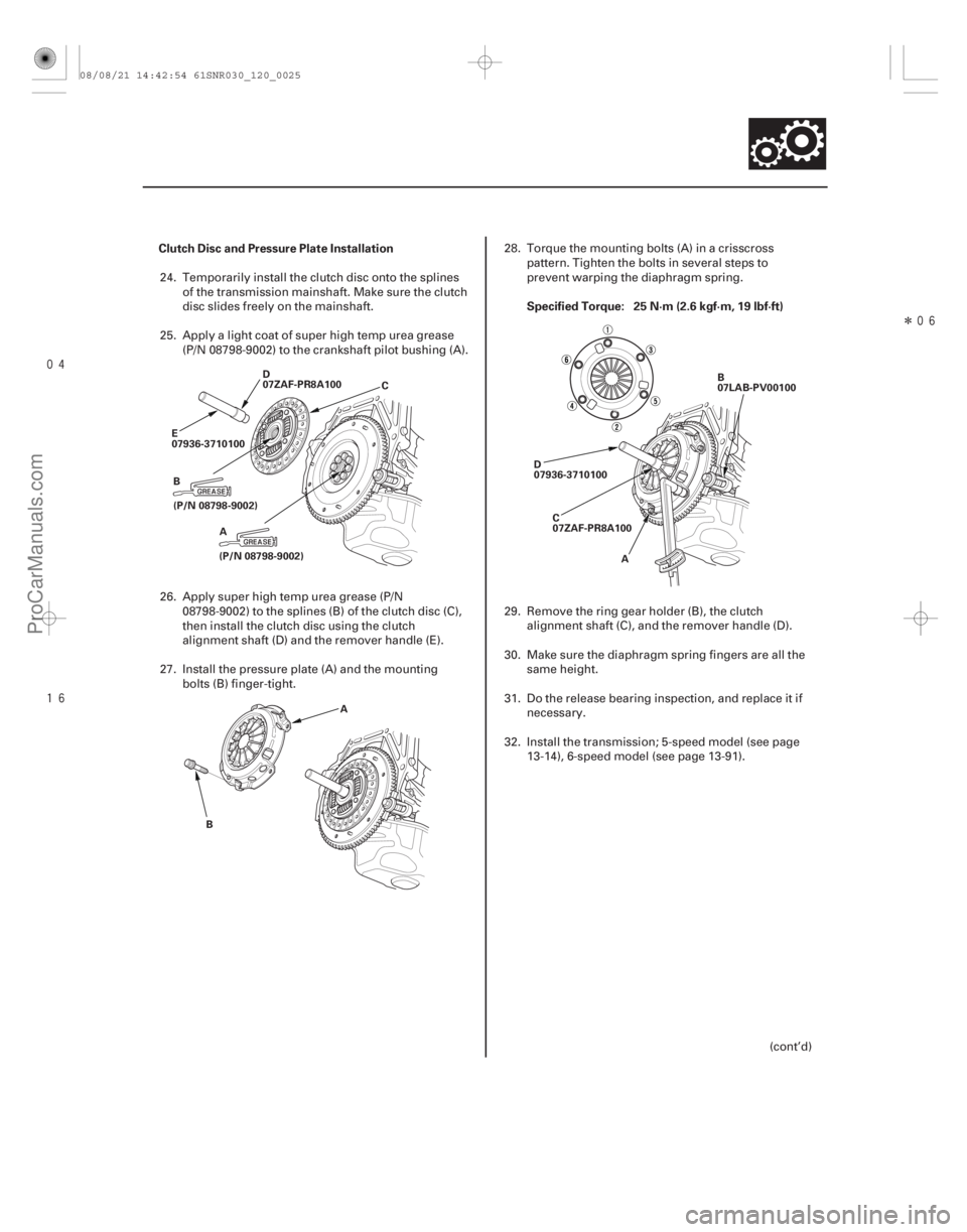
Clutch Disc and Pressure Plate Installation
Specified Torque: 25 N·m (2.6 kgf·m, 19 lbf·ft)
12-23
D
07ZAF-PR8A100
E
07936-3710100
(P/N 08798-9002) C
B (P/N 08798-9002)A
B A D
07936-3710100
C
07ZAF-PR8A100 B
07LAB-PV00100
A
24. Temporarily install the clutch disc onto the splines of the transmission mainshaft. Make sure the clutch
disc slides freely on the mainshaft.
25. Apply a light coat of super high temp urea grease (P/N 08798-9002) to the crankshaft pilot bushing (A).
26. Apply super high temp urea grease (P/N 08798-9002) to the splines (B) of the clutch disc (C),
then install the clutch disc using the clutch
alignment shaft (D) and the remover handle (E).
27. Install the pressure plate (A) and the mounting bolts (B) finger-tight. 28. Torque the mounting bolts (A) in a cri
sscross
pattern. Tighten the bolts in several steps to
prevent warping the diaphragm spring.
29. Remove the ring gear holder (B), the clutch alignment shaft (C), and the remover handle (D).
30. Make sure the diaphragm spring fingers are all the same height.
31. Do the release bearing inspection, and replace it if necessary.
32. Install the transmission; 5-speed model (see page 13-14), 6-speed model (see page 13-91).
(cont’d)
08/08/21 14:42:54 61SNR030_120_0025
ProCarManuals.com
DYNOMITE -2009-